PART XI. THE VALVE-GEAR.
Reading edition
Question 182. What is meant by the valve-gear of a locomotive?
Answer. By the valve-gear is meant the arrangement of eccentrics, rods, links, rockers, etc., by which the valves are moved and their motion regulated.
Question 183. What is required of the valve-gear in working a locomotive?
Answer. It must be so arranged that the locomotive can be run either backward or forward, and so that the motion of the wheels can be reversed quickly and with certainty. It should enable the runner to employ the greatest power of the engine by admitting steam into the cylinders during the whole or nearly the whole of the stroke of the pistons, or when less power is required, to use the steam more economically by working it expansively, which latter is accomplished with the present appliances by changing the travel of the valve.
Question 184. How is the valve-gear constructed so as to run the engine either backward or forward?
Answer. As already explained, in answer to question 76, two eccentrics are provided for each cylinder. These are set so that one of each pair will run the locomotive in one direction, and the other two the reverse way.
Question 185. How must the eccentrics for each cylinder be set in order that the one may run the engine forward and the other backward?
Answer. This can be best explained by reference to fig. 100, in which the piston, P, is represented at the beginning of the backward stroke, and the valve V has the requisite lead and is just about to open the front steam-port. It is obvious that, in order to complete the backward stroke of the piston, the front port must be opened to admit steam into the front end of the cylinder, and therefore the valve must be moved in the direction indicated by the dart a. To do this, the upper arm of the rocker r must move in the same direction, and the lower arm must be moved the reverse way, as indicated by the dart e. If the crank is intended to move in the direction indicated by the dart N, then the centre of the eccentric must be above the centre of the shaft or axle, in order to move the rocker in the direction indicated by the dart e. Supposing, however, it was intended to move the crank the reverse direction, as shown by the dart N in fig. 101; it is evident in that case that the valve must be moved in the same direction as before, in order to open the front steam-port and thus admit steam to force the piston back. But if the crank turns in the direction shown by the dart N, fig. 101, then the centre of the eccentric must be placed below the centre of the axle in order to move the lower rocker arm in the direction of the dart e and the valve in that indicated by a. It will thus be seen that the centres of the eccentric for running forward and that of the one for running backward must be placed, the one above and the other below the centre of the axle at the beginning of the stroke of the piston, as shown in figure 101.

Fig. 100.
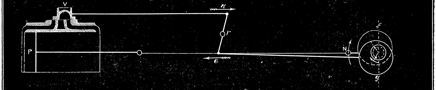
Fig. 101.

Fig. 102. Scale ³⁄₈ in. = 1 foot.
Question 186. Why is it that the centres of the eccentrics are not placed opposite to each other on the axle?
Answer. Because before the beginning of the stroke of the piston it is necessary to move the valve from its middle position a distance equal to the lap before the steam-port begins to open. If we have a valve like that shown in fig. 10—that is, without any lap—the centres of the eccentrics could be placed at right angles, or, as mechanics say, “square” with the crank, as was shown in fig. 11, and exactly opposite to each other, because such a valve begins to take steam as soon as it moves from the middle of the valve-face. If, however, we have a valve like that shown in fig. 27, it is plain that before it will admit or take steam, as it is called, in either of the steam-ports, it must be moved from the centre of the valve-face, or its middle position, a distance equal to the lap, L. For this reason, therefore, the eccentric, instead of being placed at half-throw,[49] as it is called, must be so far ahead of the middle position as to have moved the valve a distance equal to the lap, and if any lead is given to the valve, equal to the lap and lead together. In figs. 100 and 101, f g is a vertical line at right angles to the crank at the beginning of the stroke. It will be seen that the centre of each of the eccentrics is set far enough ahead of this line to give the valve the required lead. When the piston reaches the back end of the cylinder, the two eccentrics will occupy the position shown in fig. 102, in which position the lower one would move the valve so as to turn the crank in the direction of the dart N, and the upper one in the reverse direction. It will be seen that in this position both of the eccentrics are again ahead of half-throw, when the piston is at that end of its stroke.
Fig. 103.
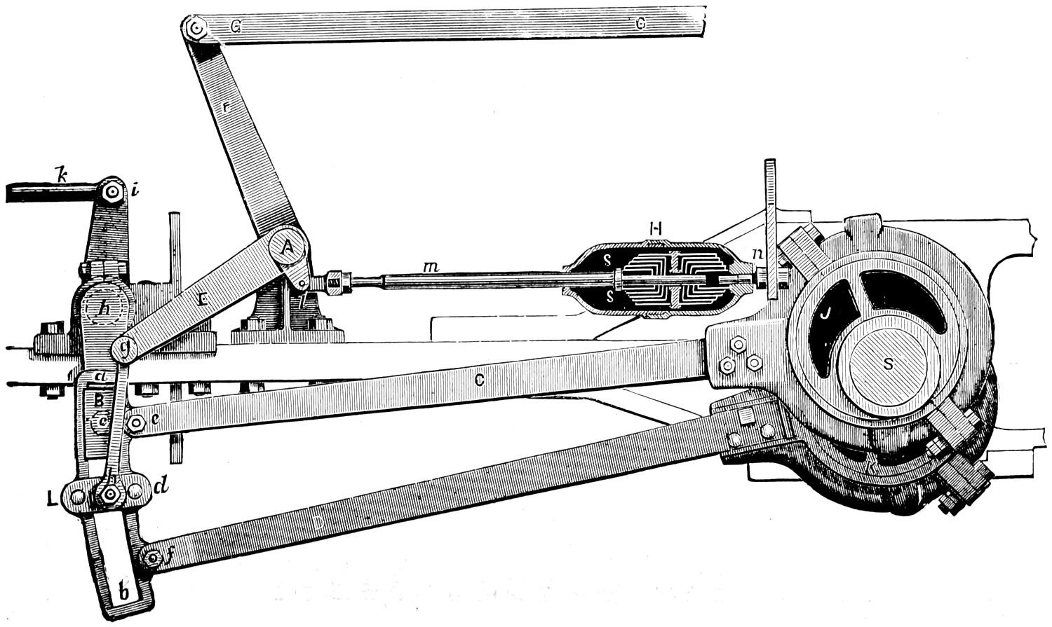
Scale ³⁄₄ in. = 1 foot.
Question 187. How is the motion of either eccentric communicated to the valve?
Answer. The ends of each pair of eccentric-rods are connected together by a link, a b, fig. 103. This link has a curved groove or slot, a b, in it, in which a block, B, fits accurately, so that it can slide freely from one end to the other. This block is attached to the lower rocker-arm by a pin, c, which works freely in the block. The two eccentric-rods C and D are attached to the ends of the link at e and f by pins and knuckle-joints. It is apparent that if the link is down, or in the position shown in fig. 103 and also on a smaller scale in fig. 104, the motion of the upper eccentric-rod, which is usually used for the forward motion, will be imparted to the rocker, and thus to the valve, and when the link is in the position shown in fig. 105, that the valve will be moved by the lower or backward eccentric-rod B. In order to reverse the engine, it is then only necessary to provide the means of raising and lowering the links. This is done by a shaft, A, fig. 103, called a lifting-shaft, which has two horizontal arms, E,[50] one for each link, and a vertical arm, F. The links are suspended from the ends of the horizontal arms by rods or bars, g h, called link-hangers, which are connected to the links and to the arms above by pins, which enable the hangers to vibrate freely. The lower pin is attached to a plate, L d, called a link-saddle, which is bolted to the link. The vertical arm of the lifting-shaft is connected by a rod, G G, called the reverse-rod, to a lever O, O, Plate II. in the cab called a reverse-lever, the construction of which will be explained hereafter. This lever is worked by the locomotive runner, and by moving the upper end of it forward, the link will be lowered, and the rocker and valve will be moved by the forward eccentric; and if the reverse-lever is moved back, the link will be raised, and the backward eccentric will move the valve. When this is done, the valve-gear is said to be thrown into the forward or backward motion, or forward or back gear.
Fig. 104.
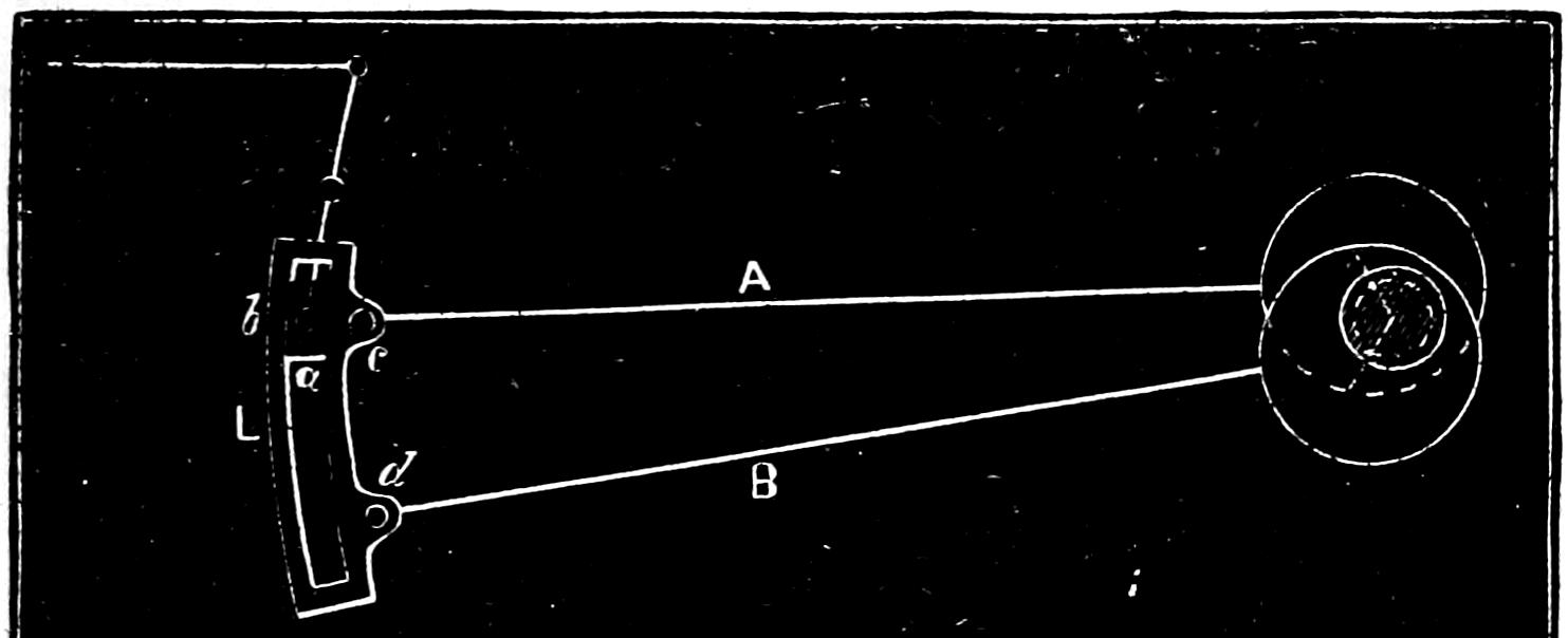
Fig. 105.
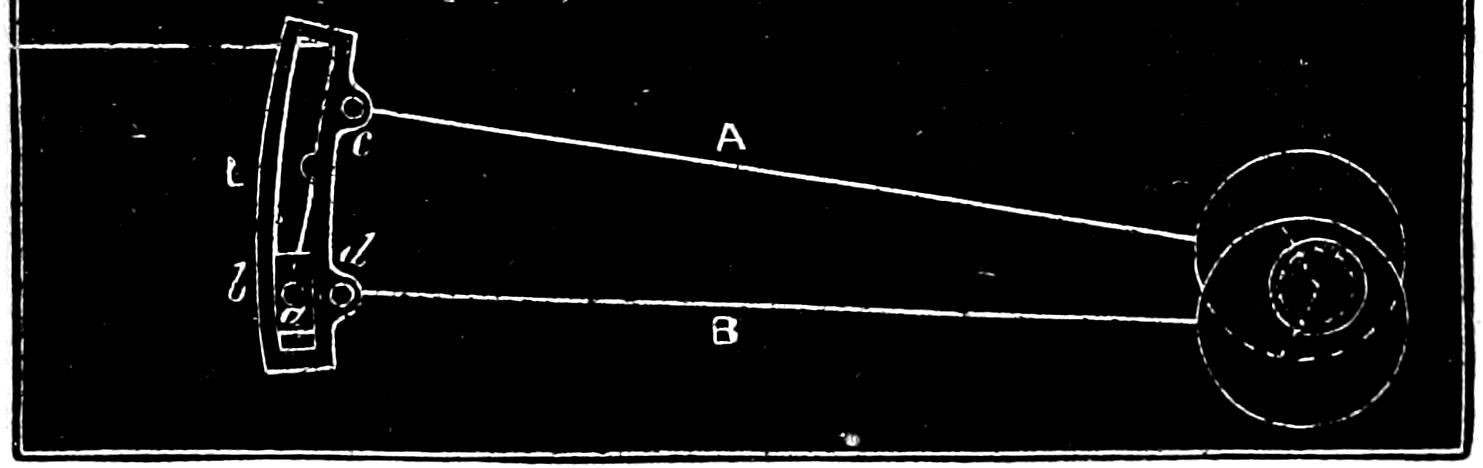
Scale, ³⁄₈ inch = 1 foot.
Fig. 106.
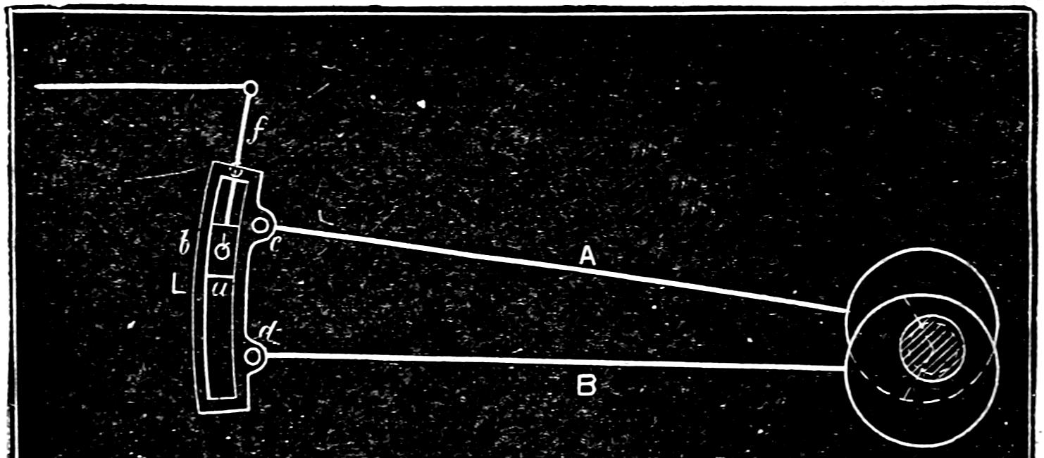
Fig. 107.
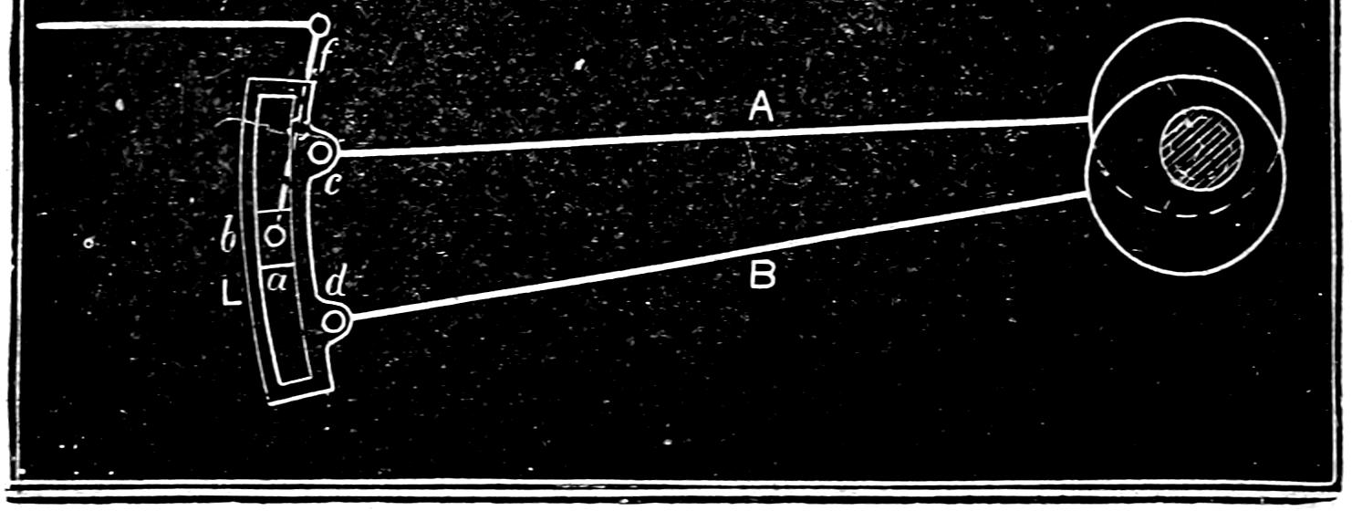
Scale, ³⁄₈ inch = 1 foot.
Question 188. How is the travel of the valve changed by the motion of the link?
Answer. By either raising or lowering the link, so that the link-block and rocker-pin will be some distance above or below the eccentric-rods. Thus in fig. 104, the motion of the upper eccentric-rod, and in fig. 105 that of the lower or back eccentric-rod is communicated to the rocker-pin and the valve. If, however, the link should be raised so that the link-block and rocker-pin are somewhat below the upper or forward eccentric-rod, as shown in fig. 106, then the motion imparted to the rocker and valve will partake somewhat of that of the upper and also of the lower eccentric-rod. So long as the rocker-pin is above the centre of the link, the motion of the valve will partake most of that of the upper or forward rod, and the engine will then run forward, but when the rocker-pin is below the centre of the link, its motion will be influenced more by the back eccentric-rod, and the engine will then run backward.
The motion of the link, which is somewhat complex and difficult to understand clearly, will perhaps be understood better if we represent it in a number of successive positions of the whole stroke of the piston, as was done to show the motion of the eccentric in figs. 11 to 24. We will therefore suppose that the link is in what is called full gear forward, as shown in figs. 103 and 104. In fig. 108 the link is in the position it would occupy at the beginning of the stroke of the piston; in fig. 109 it is in that which it will be in when the piston has moved four inches; in fig. 110, when it has moved eight inches; in fig. 111, twelve; and in figs. 112, 113 and 114, sixteen, twenty and twenty-four inches. Figs. 114 to 119 represent the successive positions of the link during the return stroke. In order to show the different positions of the link we have represented on a larger scale, in fig. 120, the successive positions of the centre line of the link, which will indicate the motion imparted by it to the rocker. In order to designate each of these positions, the centre lines in fig. 120 are numbered + and -0, 4, 8, etc., etc., to correspond with similar numbers in figs. 108 to 119.
Fig. 108.
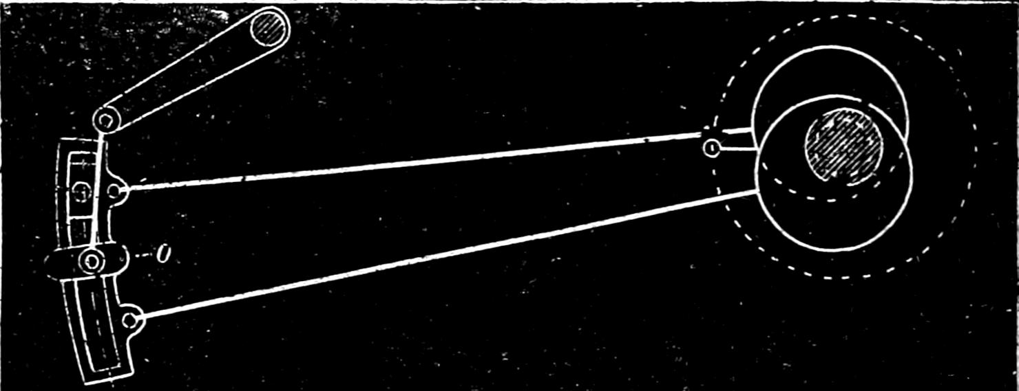
Fig. 109.
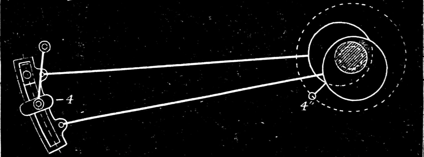
Fig. 110.
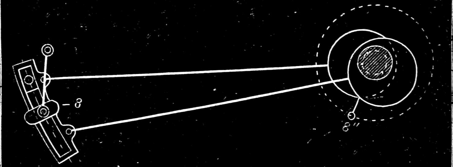
Fig. 111.
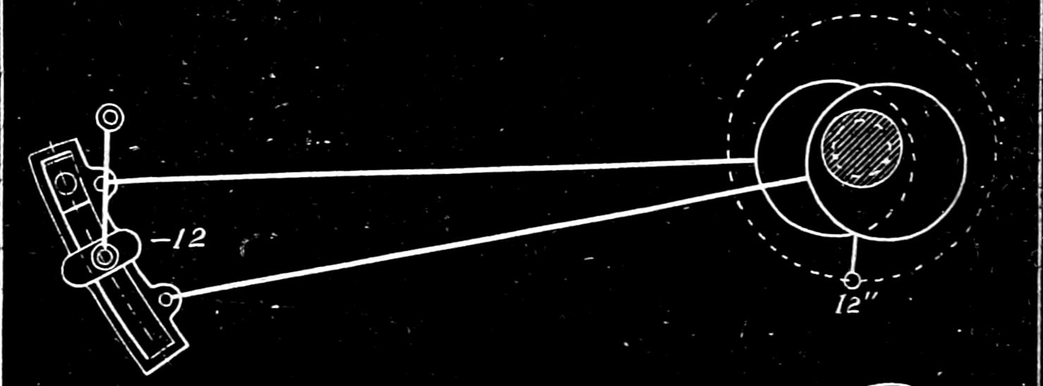
Fig. 112.
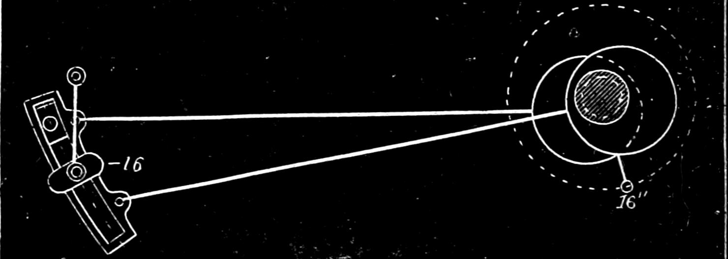
Fig. 113.
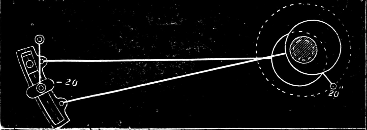
Fig. 119.
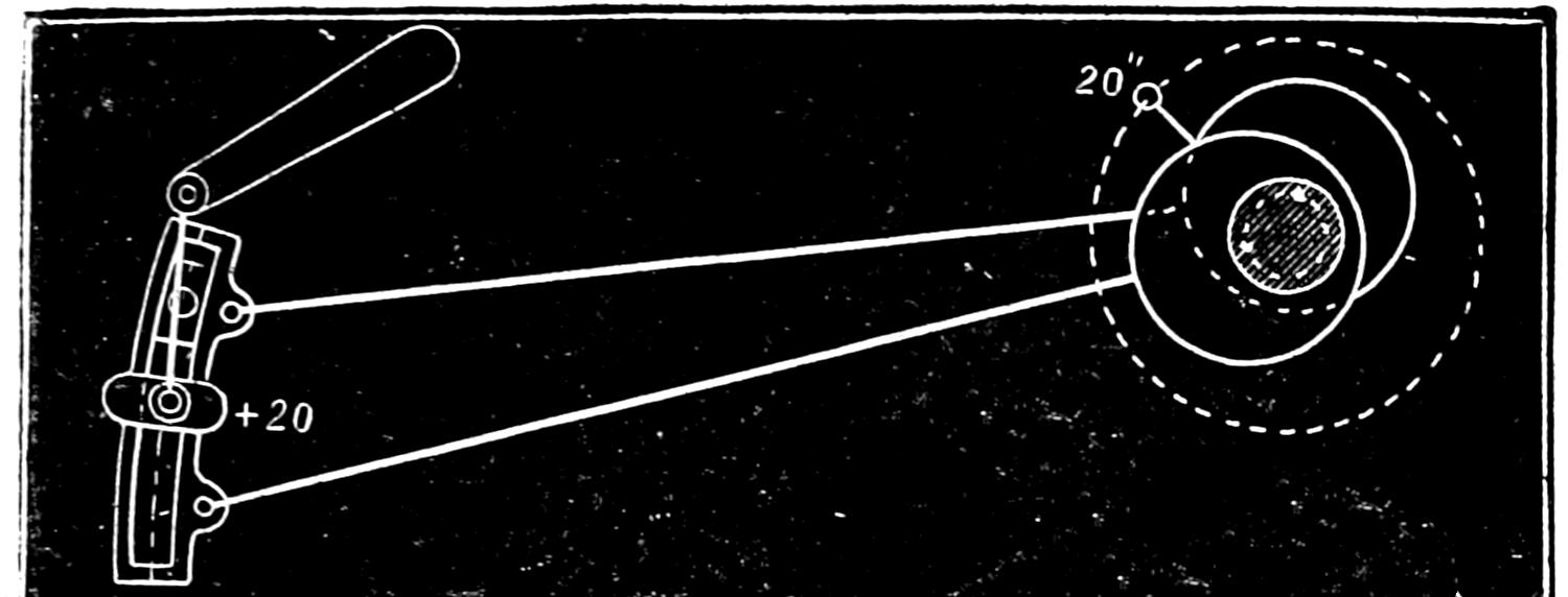
Fig. 118.
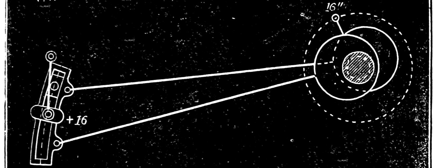
Fig. 117.
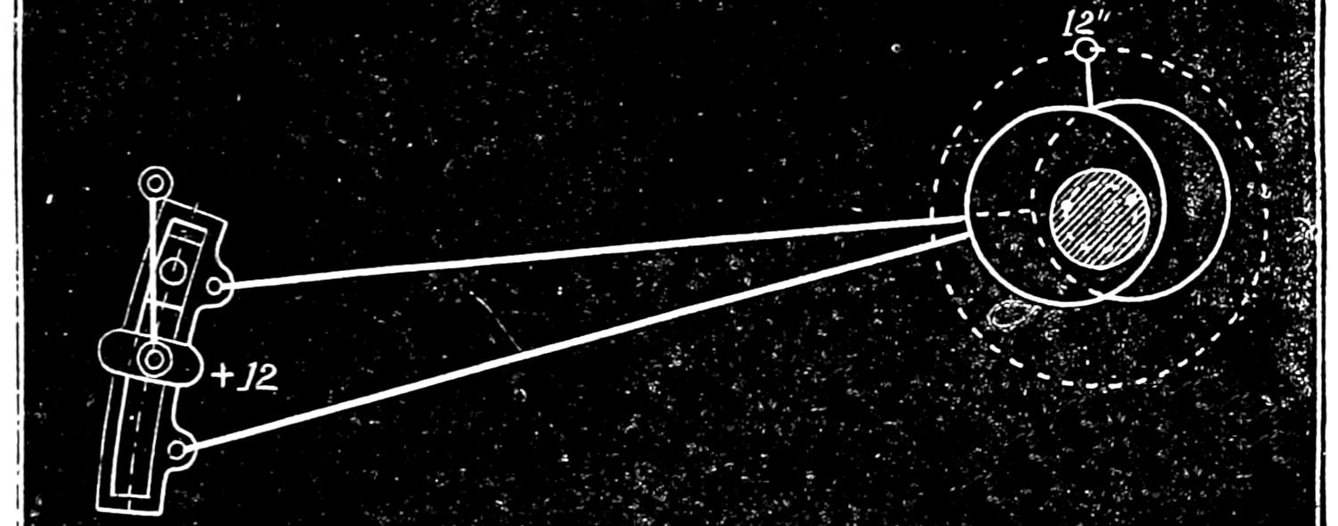
Fig. 116.
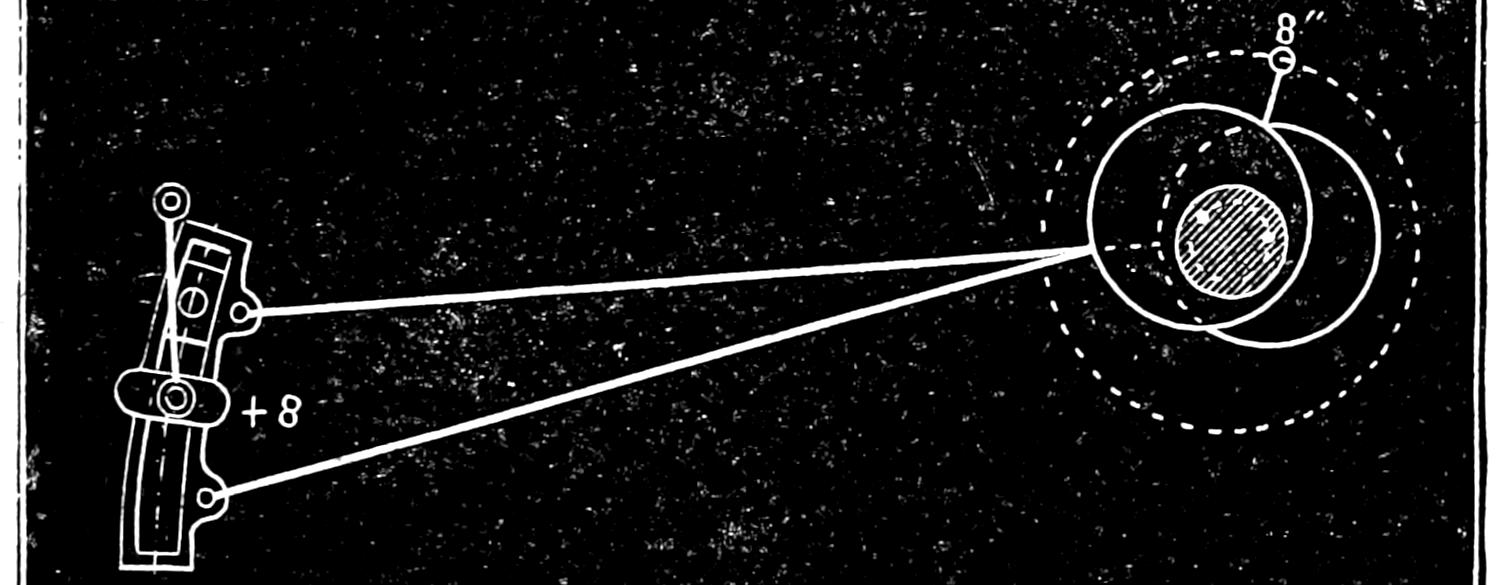
Fig. 115.
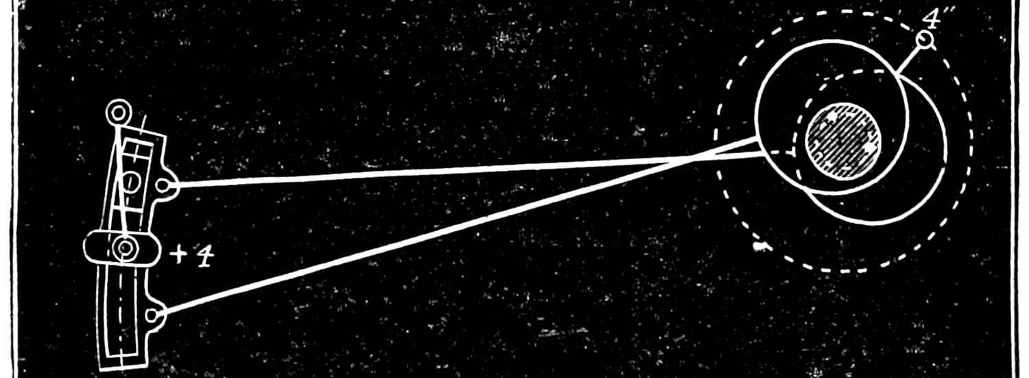
Fig. 114.
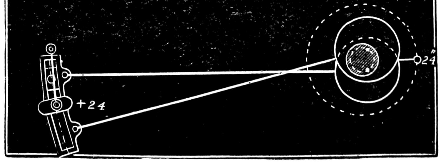
Scale ³⁄₈ in. = 1 foot.
Fig. 120.
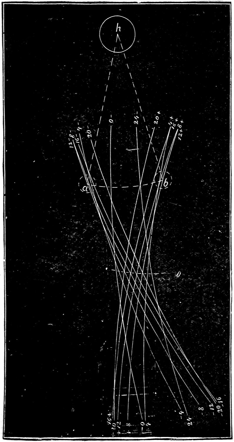
Scale ³⁄₁₆ in. = 1 inch.
Fig. 121.
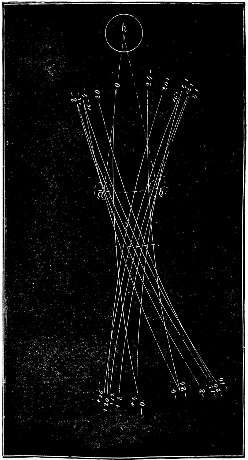
Scale ³⁄₁₆ in. = 1 inch.
Fig. 122.
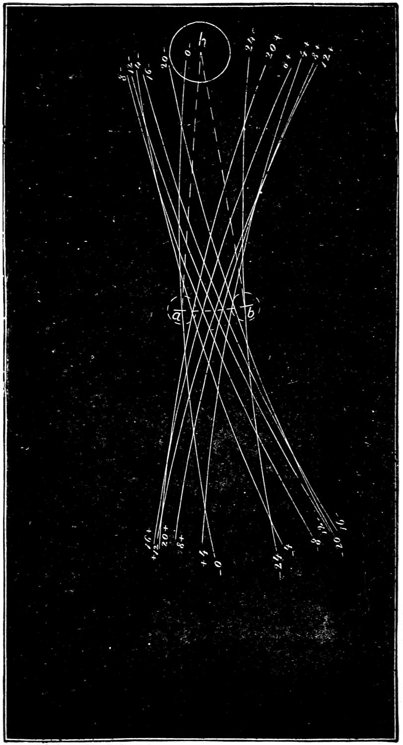
Scale ³⁄₁₆ in. = 1 inch.
Thus the line -0 -0 represents the position of the centre of the link which it occupies at the beginning of the stroke as shown in fig. 108. The line -4 -4, that represented by fig. 109, when the piston has moved 4 in. The lines -8 -8, -12 -12, -16 -16, -20 -20, 24 24, +4 +4, etc., the successive positions of the centre of the link represented in figs. 108 to 119. The dotted lines h a and h b represent the two extreme positions into which the rocker-arm would be moved by the action of the link. It will be seen that when the link is in the position shown, it imparts the full stroke of the eccentrics to the rocker-pin and consequently to the valve. We will now suppose that the link is raised up as shown in fig. 106, so that the position of the rocker-pin is just half-way between the end of the eccentric-rod and the centre of the link. This position is called half-gear. In fig. 121 the different positions of the centre line of the link and of the rocker have been laid out for half-gear in the same way as was done for full-gear before. From this it will be seen that the travel, a b, imparted to the rocker-pin and valve by the link when it is in the position shown, instead of being 5 in. is only 3¹⁄₂ in. In fig. 107 the link is raised up, so that the rocker-pin is in the centre of it or midway between the eccentrics. This position is called mid-gear. The successive positions of the centre line of the link in this position have been laid down in fig. 122 in the same way as was done for full and half-gear. The movement of the rocker, it will be seen, is, for mid-gear, only 2¹⁄₂ in. These diagrams show that when the rocker-pin is opposite the eccentric-rod, the valve receives the full throw of the eccentric, and that the motion imparted by the eccentric diminishes as the rocker-pin approaches the centre of the link, so that, with eccentrics having 5 in. throw and a valve with ⁷⁄₈ lap and ¹⁄₈ in. lead, we can increase or diminish the travel of the valve from 2¹⁄₂ to 5 in. by simply raising or lowering the link, which is done by the reverse-lever.
Question 189. What is the effect of this variation of travel on the working of the valve and the admission and release of steam to and from the cylinder?
Answer. It is almost precisely the same as that which is effected by increasing or diminishing the throw of the eccentric, which was explained in the answer to Question 52. In order to show this effect more clearly, we have represented by motion-curves,[51] fig. 123, the movement imparted to the valve by the link when it is in full, half and mid-gear, as illustrated in the preceding figures. The curve for full-gear is engraved in full heavy lines; that for half-gear in lighter lines, and for mid-gear in dotted lines. From these curves it will be seen that when the valve is worked in full-gear the steam-port is opened wide at 2 in. of the stroke and steam cut off at 21 inches. When the valve is worked in half-gear the port is not at any time opened wide and steam is then cut off at 17¹⁄₂ in. of the stroke, and when worked in mid-gear the greatest opening of the steam-port is no greater than the lead and the cut-off occurs at 4 inches of the stroke.
It is of course possible to work the link in any intermediate position between those which we have represented. Usually the reverse-lever is arranged so that the steam will be cut off at 6, 8, 10, 12, 15, 18, and 20 inches of the stroke.
Question 190. What is the greatest and the least admission of steam possible with the ordinary link motion?
Answer. With 24 in. stroke of piston and 5 in. travel and ⁷⁄₈ in. lap, steam can be admitted as shown by the motion-curves during 21 in. or 87¹⁄₂ per cent. of the stroke, and can be cut off at about 4 in. or 16²⁄₃ per cent. It will be seen, however, that in mid-gear the motion-curve becomes a straight line, and that the pre-admission of steam, that is the admission of steam before the piston reaches the end of the stroke, is equal to that admitted after, so that it is impossible to work the locomotive with the link in that position. Practically it is found that no useful work can be done with a link if the steam is cut off at less than six inches, or one-fourth of the stroke. Even then the opening of the steam-ports is so small that the steam which enters the cylinders is very much wire-drawn.
Question 191. How are the curves drawn which represent the motion of the valve?
Answer. These motion-curves as produced by the link-motion are very difficult to draw, as the motion of the link is extremely complicated. It is doubtful, therefore, whether those who have no knowledge of mechanical drawing will be able to understand the following description of the method of doing it, which we will try to make as clear as possible.
Fig. 123.
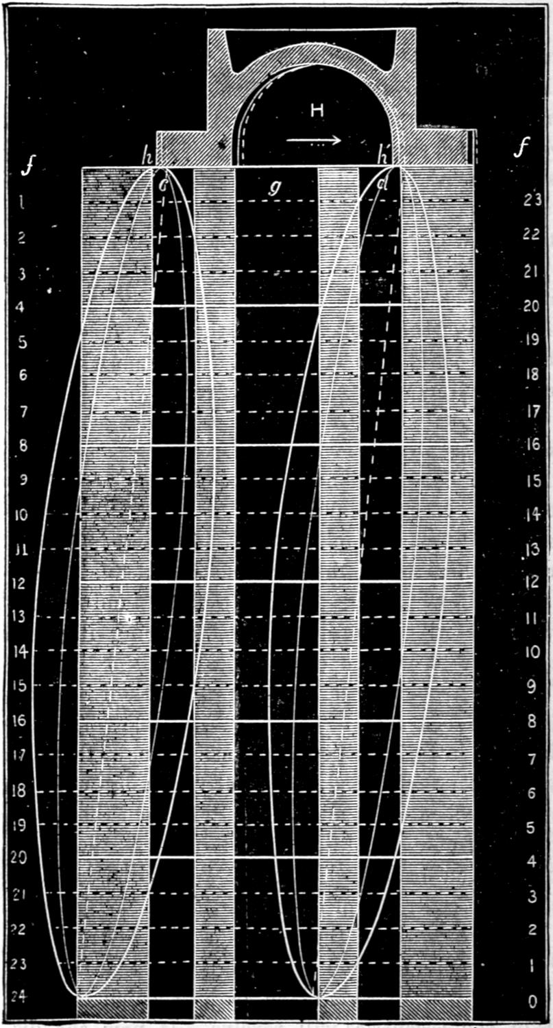
Scale ³⁄₁₆ in. = 1 inch.
Fig. 124.
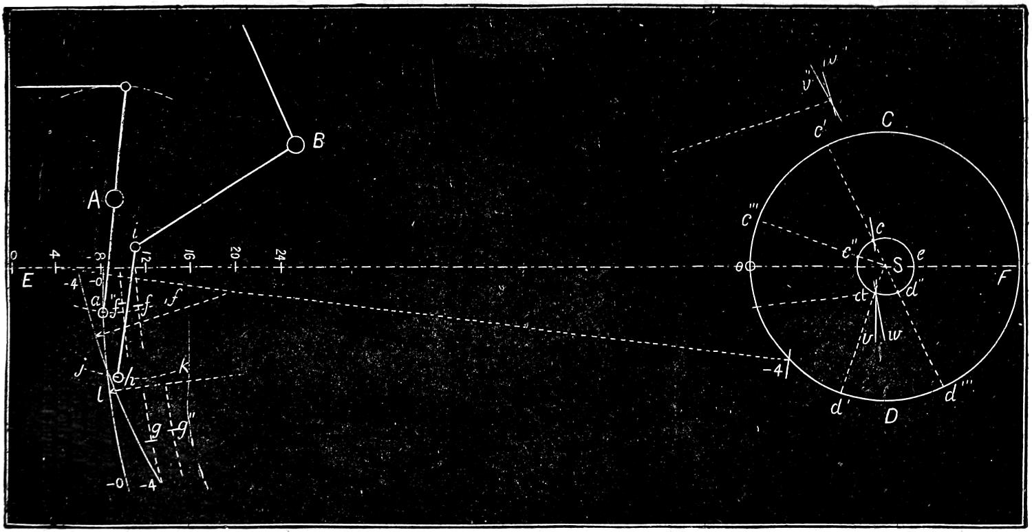
Scale ³⁄₄ in. = 1 foot.
In the first place, the centre S, fig. 124, of the axle, A, of the rocker, and B of the lifting-shaft, must be laid down in their proper positions. If, now, the valve has ⁷⁄₈ in. lap and ¹⁄₈ lead, the lower rocker-pin must be one inch ahead of its middle position when the piston is at the front end of the cylinder, and at the beginning of the backward stroke. We will, therefore, mark the centre, a, of the rocker-pin in this position. If from the centre of the axle a circle, c d e, be drawn whose diameter is equal to the throw of the eccentrics, this circle will represent the path in which the centres of the eccentrics will revolve. If, now, the distance from the centre of the axle to the centre of the lower rocker-pin, a, when the latter is in its middle position, be taken for a radius,[52] and from the position of the rocker-pin at the beginning of the stroke as a centre, the circle representing the path of the eccentrics be intersected at two points, c and d, the points of intersection will represent the positions of the centres of the forward and backward eccentrics. Having determined these positions, draw arcs of circles, f and g, from these centres with a radius equal to the distance from the centres of the eccentrics to the centres of the pins which connect the rods to the link. It is evident that at the beginning of the stroke the centres of the pins in the link must each be in one of these arcs. But the link is suspended by the hanger, i h, which oscillates from the end, i, of the lifting-arm, which for any one point of cut-off is stationary; and therefore the point of suspension of the link must always be in the arc, j k, described from the centre of the pin, i, in the lifting-arm, with a radius equal to the length of the hanger. There are, therefore, three points in the link, each of which must be in one of the arcs which have been drawn, and which will determine the position of the link. This can be done easiest by drawing the link, L, fig. 125, on a stiff piece of paper, m n, and cutting off the back, p q, of it through the centres of the pins, s and t, and also cutting out a triangular piece, u, the apex of which will correspond with the centre of the point of suspension, o. By placing this piece of paper on the drawing it can be moved, so that the three centre points, s, t and o, will respectively conform with the arcs, f g and j k, fig. 124. In this position the piece of paper will then be in the position of the link for the point of the stroke represented. By marking the centres of the link-pins on the arcs f and g, and from them as centres, with the length of the rods used to draw the arcs, two other arcs, v, w, be drawn intersecting each other, the point d, where they intersect will be the centre from which the centre line of the link can be drawn with a radius, l d, equal to the distance from the centre of the eccentrics to the centre of the link. This will give the first position -o -o, of the centre line of the link. As the rocker-pin must always be in the centre of the link, it is obvious that the point at which the centre-line of the link intersects the arc in which the rocker-pin oscillates must be the position of the centre of the rocker-pin. With this determined the position of the valve can easily be located.
Fig. 125.
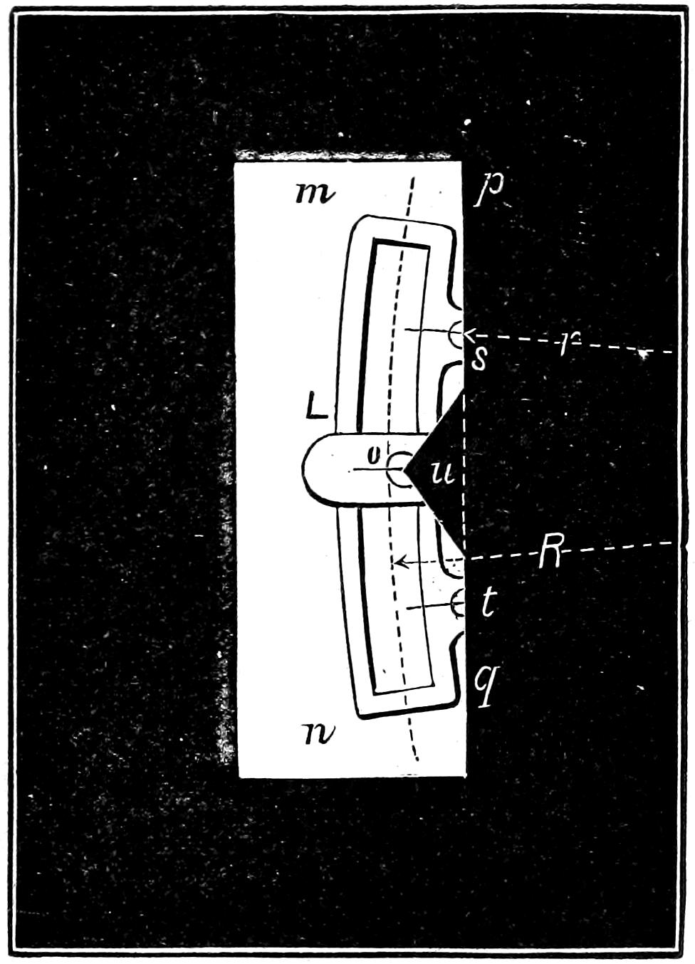
Scale, ³⁄₄ in. = 1 foot.
In order to represent the link at any other point of the stroke, say after the piston has moved four inches, the position of the crank must first be laid down. To do this, allowance must be made for the irregularity due to the angularity of the connecting-rod, which was explained in answer to Question 54. From the centre of the axle, a circle, C D, whose diameter is equal to the stroke of the piston, is first drawn, which will represent the path of the crank-pin. A horizontal centre line, E F, should also be drawn through the centre of the axle and the centre of the cylinder. The intersection o of this line with the path of the crank-pin will be the position of the latter at the beginning of the stroke. If from this point a distance, o o, be laid off on the centre line equal to the length of the connecting-rod,[53] it will give the position of the wrist-pin at the beginning of the stroke, so that from this its successive positions for each inch of the stroke can be laid off. From its position after the piston has made say four inches of the stroke as a centre, and the length of the connecting-rod as a radius, if the path of the crank-pin be intersected at -4, the point of intersection will represent the position of the crank-pin at four inches of the stroke. The distance from o to -4 is equal to 44 degrees of the whole circle. The eccentrics, being attached to the axle, of course move the same number of degrees that the crank does, and therefore, in order to determine their position when the crank has moved any distance, it is only necessary to move them as many degrees as the crank has. This can be done very easily by extending the radii of the eccentrics, when they are in the first position, until they intersect the path of the crank-pin at c′ and d′. By stepping off from the latter points of intersection a distance c′ c‴ and d′ d‴, equal to o -4, which the crank has moved, and then drawing other radii from the two points c‴, d‴, their intersection, c″ d″, with the path of the eccentrics will represent the position of the centres of the eccentrics when the crank is at -4. Having determined the position of the eccentrics, the link can be laid down as before, that is, from c″ and d″ as centres and with the length of the eccentric-rods as a radius arcs, f″ and g″, are drawn. Then with the paper template the positions of the centres of the link-pins in these arcs are determined and marked, and from them with the length of the eccentric rods as a radius, two intersecting arcs, v″, w″, are drawn, whose intersection gives the centre of the link from which its centre line, -4 -4, is drawn. This will give the position of the rocker-pin for another point of the stroke. In a similar manner its position can be determined for any number of points of the stroke, from which the position of the valve can easily be determined and laid down on the diagram for the motion-curve as was described in the answer to Question 44. Of course the valve will be moved from its middle position the same distance that the rocker-pin is,[54] only in an opposite direction. In order to lay down the position of the valve on the diagram for motion-curves, it is, therefore, only necessary to draw it in the same relative position as that of the rocker-pin which is given by the point of intersection of the center line of the link with the path in which the rocker-pin oscillates. To construct the motion-curves it is necessary to determine the positions of the valve for different points of the stroke and mark them on the horizontal lines which represent the respective positions of the piston. Curves are then drawn through these points, either by hand or by constructing templates. The more points there are determined, the more accurate will be the curves. It is, therefore, best to lay down the position of the valve for each inch of the stroke of the piston. They should also be drawn full size, which of course was impossible for the illustrations which are given herewith.
Question 192. Is there any other method of drawing these motion curves?
Answer. Yes: models which show the working of the valve-gear have been constructed with a pencil, to which the reciprocating motion of the valve is imparted, and which traces a curve on a surface having the same motion as the piston. This method has been employed by the writer in an instrument which he has applied to the locomotive itself. The principle upon which it works will be understood by supposing that the steam and exhaust-ports as represented in the diagram for motion-curves, fig. 123, be drawn on a board, A B C D, fig. 126, but instead of standing vertical, as in fig. 123, they are represented in a horizontal position, and the board on which they are drawn is fastened to the cross-head, L, so that the former will move backward and forward simultaneously with the latter and the piston. A small shaft, F, is attached to suitable supports, j, which are fastened to the guides. This shaft has two arms, G and E, one vertical and the other horizontal and of the same length. The upper end of the vertical one, G, is then attached to the valve-stem or rocker-arm by a short connecting-rod, H, or other suitable means, so that the movement of the valve-stem will be imparted to the arm and shaft. Of course the end of the horizontal shaft then has exactly the same motion vertically that the valve-stem and valve have horizontally, with the very trifling inaccuracy due to the fact that the movement of the one is in a straight line, whereas the other is in the arc of a circle.
Now if a pencil, P, is attached to the end of the horizontal arm, E, and is set so that its point indicates the exact position of the steam edge, h, of the valve, as shown in fig. 123, it is obvious that when the piston and board have moved four inches, the pencil will have moved downward and have drawn the portion of the motion-curve from h to i; and when the piston has moved eight inches the curve will be drawn to j, and at 12, 16, 20 and 24 inches of the stroke the curve will be drawn to k, l, m and n. During the return stroke a corresponding curve, n o h, will, of course, be drawn. With such an instrument curves can be drawn for any position of the link, and they will show the exact movement of the valve during the whole stroke, and will indicate all the defects resulting from bad proportions or construction, lost motion in the parts, or other causes of error or irregularity.
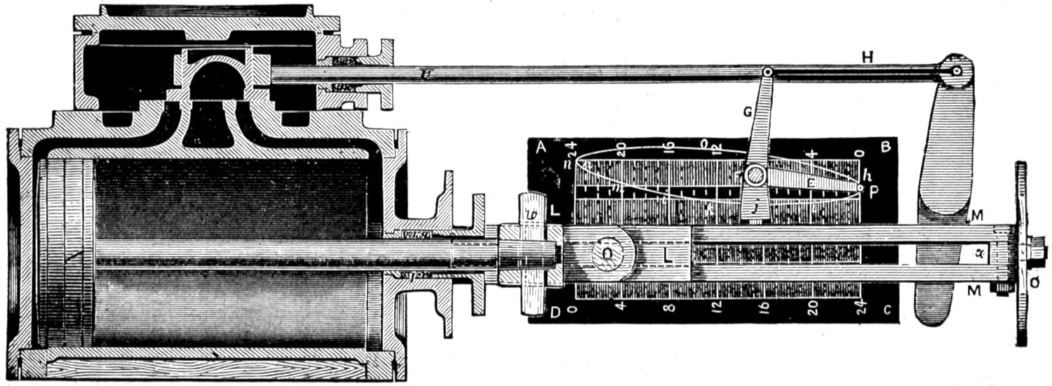
Fig. 126.—Scale ³⁄₄ in. = 1 foot.
In using this instrument, however, it is impracticable to attach a board to the inside of the cross-head, and it must therefore be fastened to the outside. The horizontal arm E should be made of thin steel, so as to form a spring. The end has a small boss[55] with a hole in it ³⁄₁₆ of an inch in diameter. This hole has a screw thread cut in it, into which an ordinary hard drawing pencil is screwed. The spring is so arranged that the pencil will not be in contact with the board unless it be pressed against it. The locomotive is then placed on a smooth piece of track with steam on and run very slowly, so that a person walking alongside can press the pencil against the surface of the board, which should be covered with drawing paper. By watching the cross-head when it reaches the end of the stroke, the pencil can then be pressed against the paper and kept in contact through the whole stroke and instantly released when the motion-curve is completed. The link can then be placed in another position, and thus any number of curves can be drawn, which will furnish the most accurate means of analyzing the motion of the valve.
In practice it is best not to draw the lines which represent the edges of the ports, until after the curves are drawn and the paper removed from the board. A centre line must, however, be drawn on the engine from which to lay off the ports. This can be done by placing the valve in its middle position, and then fastening the shaft F in that position with a nut which should be provided for that purpose on the end of the shaft. After it is fastened in this position, detach the connecting-rod H, and with one stroke of the piston a centre line can be drawn with the pencil P. From this centre line the edges of the ports can easily be laid off and drawn on the paper after it is taken off the engine.
Question 193. Can the position of each edge of the valve, with any given amount of travel, be shown in its relation to the ports by one motion-curve, or is it necessary to draw such curves for each edge of the valve, as shown in fig. 28?
Answer. One motion-curve is sufficient to represent the position of any part of the valve during the entire stroke. This will be apparent if it is remembered that each motion-curve is exactly like the others, as shown in fig. 28, the only difference being that the ports occupy different positions in relation to the curves. It is, therefore, only necessary to draw lines to represent the relative positions of the ports to the other curves to show the entire motion of the valve by one curve. To illustrate this it will be assumed that a motion-curve, h i j k l m n o p, and a centre line, a b, fig. 127, have been drawn with the instrument described in the answer to the previous question. The centre line a b, which will be equal in length to the stroke of the piston, should then be divided into inches, and lines ff, 23 1, 22 2, etc., should be drawn through the points of division and at right angles to a b. If, now, we want to show the movement of the front steam edge of the valve in relation to the corresponding steam port, a line, t, should be drawn perpendicular to f f, to represent that edge of the valve at the beginning of the stroke. As it is impossible to determine accurately the position of this steam edge at the beginning of the stroke from the motion-curve, which is then tangent[56] to the line f f, we must lay it off from the centre line, a b. This can readily be done if we remember that if a valve has ⁷⁄₈ in. lap when it is in the middle position, as shown in fig. 27, and ¹⁄₁₆ in. lead at the beginning of the stroke, it must have moved ¹⁵⁄₁₆ in. from the middle position at the beginning of the stroke as shown in fig. 28. The line t must therefore be drawn ¹⁵⁄₁₆ in. from a b to represent its proper position in relation to the motion-curve, and as it has ¹⁄₁₆ in. lead, the steam edge, h h′, of the steam-port must be drawn at that distance from t. Another line, m m′, can then be drawn to represent the width of the front steam-port, c c′. From these lines the movement of the valve in relation to the front port, c c′, and the admission of steam are shown as clearly as in fig. 28.
If now we want to represent the motion and relative position of the back steam edge of the valve in relation to its port, it is only necessary to assume that the line t represents that edge, and that the curve h i j k l m n o h represents its motion, and to draw the back steam-port in its proper relation to it. When the valve is in its middle position, as shown in fig. 27, the outside edge of the port h is ⁷⁄₈ in., or a distance equal to the lap, from the steam edge q of the valve. As the center line a b, fig. 127, represents the middle position of the edge of the valve, it is only necessary to draw a line, n n′, ⁷⁄₈ in., or the same distance from the centre line a b that the outer edge of the port d is from q in fig. 28, to represent this edge of the port in fig. 127, and another b b′, at a distance from the former equal to the width of the port, to represent its inner edge. A line, q, below the line 0 24, will represent the edge of the valve at the beginning of the forward stroke. The curves in relation to the port d will then show the motion of the valve in relation to this port, in the same way that the dotted curve d f does in fig. 28.
Fig. 127.
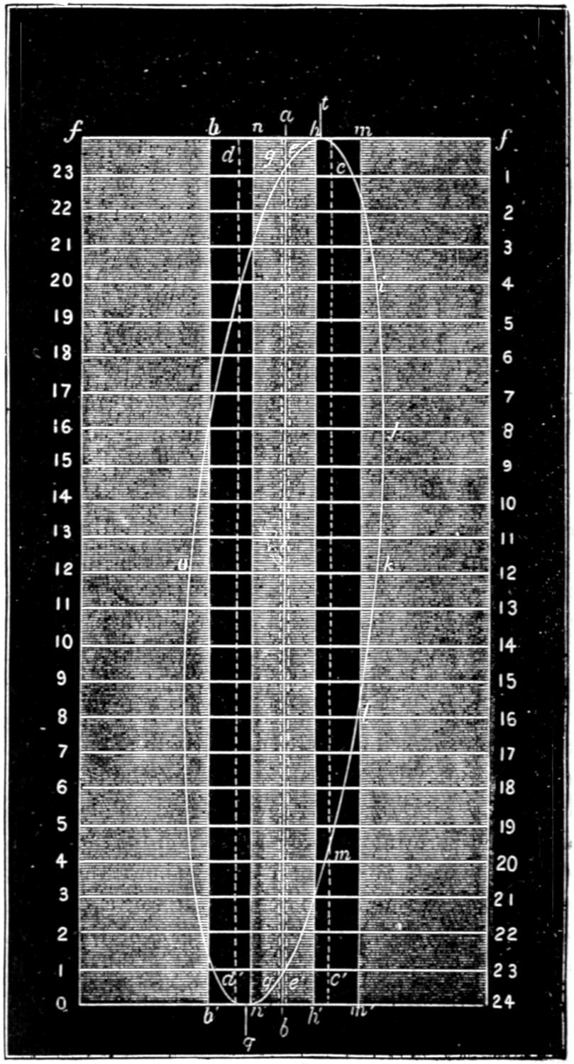
Scale ³⁄₁₆ inch = 1 inch.
If it is desired to represent the motion of the exhaust edge h′, fig. 28, of the valve, it is only necessary to imagine that the line t, fig. 127, represents that edge, and then draw in the port d in the same relation to it that it bears to the edge h′, in fig. 28. This has been done in dotted lines, c c′ and e e′, in fig. 127.
If the reader will cut a paper section of a valve like that shown in fig. 27 and place the different edges, h, i, h′ and q, so that they will successively correspond with the line t in fig. 127, the diagram will perhaps be more clear. If, for example, the paper section be placed to the right of the line t, so that the edge h will correspond with t, then it will be seen that the port c occupies the same relation to it that it does in fig. 28. If the valve be placed to the left, so that the edge q corresponds with t, then the port d will be in the same relation to it that it has in fig. 28. If the edges i and h′ be made to correspond with t, then the ports drawn in dotted lines in fig. 127 will represent the ports c and d in fig. 28.
The position of the ports in relation to the centre line of the motion-curve can be determined, if it is kept in mind that the centre line a b, fig. 127, represents the position of the different edges of the valve when the latter is in the middle of the valve-face as shown in fig. 27, and that the ports must be on the same side, and the same distance from the centre line that they are from the edge of the valve whose motion is represented. Thus if the movement of the steam edge h in relation to its port, c, was represented, the edge of the latter must be drawn on the motion diagram the same distance from the centre line that it is from h when the valve is in its middle position as shown in fig. 27. This distance is of course just equal to the lap of the valve. If the motion of the exhaust edge h′ was represented in relation to the steam port d, then the inside edge of the latter would be drawn the same distance from the centre line a b in the diagram that the inner edge of the port is from the edge h′ of the valve, which is equal to the inside lap. The exhaust port could also be drawn in the same way, but it would be liable to confuse a diagram made to so small a scale as that which has been employed for the accompanying illustrations, and it has therefore been omitted. Diagrams of this kind which are made full size will, of course, show the movement of the valve more distinctly than is possible in the space occupied by the illustrations herewith. When they are made of full size, the lines indicating the ports should be drawn of different colors, so as to distinguish them from each other easily. Such diagrams will show the position of the valve in relation to the ports, and indicate the distribution of the steam during the whole stroke. It is only necessary to refer the curve to the proper line to determine the position of the valve in relation to either of the ports for either the admission or release of the steam. If, for example, we want to observe how the admission of steam is governed by the valve, by referring to fig. 127 we see that at the beginning of the backward stroke the valve has ¹⁄₁₆ inch lead; that at 1³⁄₄ inches of the stroke the port c is wide open, as shown by the intersection of the motion-curve with the line m m′; that the valve has received its maximum backward travel at 9 inches of the stroke, and begins to close the port at 15¹⁄₂ inches, and completely closes it at 21 inches of the stroke. By referring the motion-curve to the lines n n′ and b b′, we see that the valve as shown by the line q at n′ again has ¹⁄₁₆ inch lead at the beginning of the forward stroke; that the steam port is wide open at 1³⁄₈ inches of the stroke; begins to close at 16¹⁄₄ inches, and is completely closed at 21 inches. By referring the curve to the lines e e′ and c c′ we see that the front port begins to open to the exhaust before the piston has completed its forward stroke and when it has nearly an inch to move, that it is wide open almost immediately after the piston begins its stroke, does not begin to close until the piston has moved 19¹⁄₂ inches of its stroke, and is completely closed at 23 inches of the stroke. By referring the curve to the lines d d′ and g g′, almost the same phenomena will be observed for the forward stroke. In fact from such a diagram the whole motion of the valve can be studied and analyzed with the greatest accuracy; and, as has already been shown, the motion imparted to a slide valve by a link is of so complicated a nature that it is almost or quite impossible to observe its exact nature without such diagrams.
Question 194. Can a motion diagram be constructed to represent the motion of the valve with different amounts of travel?
Answer. Yes; it is only necessary to construct motion-curves for the same diagram for each distance traveled, and they will show the movement of the valve for the given amount of travel represented by the curves. This has been done in fig. 128, which is a reduced copy of a series of motion-curves taken from a locomotive. From this diagram the movement of a slide-valve worked by the link-motion can be seen from the highest to the lowest practicable point of cut-off. For convenience of reference the curves have been numbered.
Fig. 128.
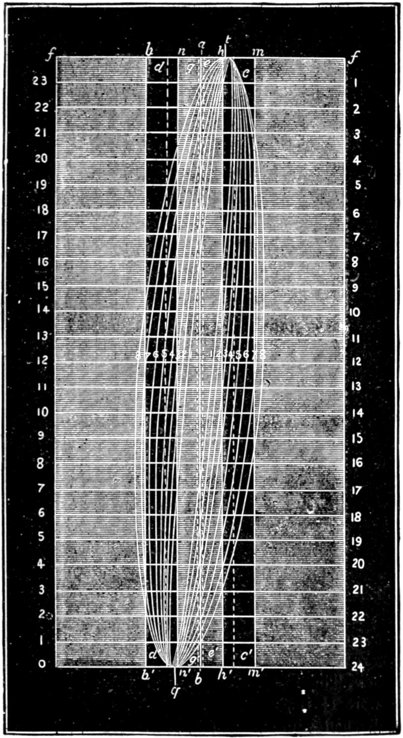
Scale ³⁄₁₆ inch = 1 inch.
The smallest travel of the valve represented by curve No. 1 is a little less than 2¹⁄₂ in., and the ports are then opened only about ⁵⁄₁₆ in., and the steam is cut off at 8 in. on the backward and 6³⁄₄ in. on the forward stroke. The exhaust is opened or the steam is released during the backward stroke at 17 in., and during the forward stroke at 16⁵⁄₈. When the valve works with its greatest travel, as represented by curve 8, it travels 5 in., and opens the steam port wide at 3 in. of the backward stroke and 2¹⁄₄ in. of the forward stroke. The steam is cut off at 20³⁄₄ and 20¹⁄₂ in., and its release takes place at 23¹⁄₈ in. of each stroke. The following table gives the greatest width of opening, the point of cut-off, the point of release, and the lead for each motion-curve on the diagram. This table has been made up from the motion-curves drawn with the instrument described in answer to Question 191, on a locomotive which had been running about eighteen months and whose valve-gear consequently was considerably worn, as s indicated by the flatness of the motion-curves on each side at the point when the motion of the valve was reversed. This flatness was caused by the lost motion in the valve-gear, the pencil remaining for a time stationary when the motion was reversed and while the parts were moving from their bearings on one side to those on the other. The curves and the table therefore show the operation not of a theoretically perfect valve-gear, but are examples of actual practice, with such imperfections as are incidental to ordinary locomotives. It will be seen that the instrument shows not only what the valve-gear should, but what it actually does do, and delineates all its imperfections.
No. of curve. Travel of valve. Width of opening of steam-port. Point of cut-off. Point of release. Lead.
Backwd stroke. Forw’rd stroke. Backwd stroke. Forw’rd stroke. Backwd stroke. Forw’rd stroke.
in. in. in. in. in. in. in. in.
1 2 ¹⁄₂ ¹¹⁄₃₂ ⁵⁄₁₆ 8 6 ³⁄₄ 17 16 ⁵⁄₈ ⁹⁄₃₂
2 2 ⁵⁄₈ ⁷⁄₁₆ ¹³⁄₃₂ 9 ¹⁄₂ 9 ¹⁄₂ 18 ⁵⁄₈ 18 ⁵⁄₁₆ ¹⁄₄
3 2 ⁷⁄₈ ⁹⁄₁₆ ¹⁄₂ 12 11 ³⁄₄ 19 ³⁄₄ 19 ⁹⁄₁₆ ⁷⁄₃₂
4 3 ¹⁄₈ ¹¹⁄₁₆ ⁴¹⁄₆₄ 14 14 20 ¹¹⁄₁₆ 20 ⁹⁄₁₆ ³⁄₁₆
5 3 ¹⁄₂ ⁷⁄₈ ²⁷⁄₃₂ 16 ¹⁄₂ 16 ¹⁄₂ 21 ¹¹⁄₁₆ 21 ¹⁄₂ ⁵⁄₃₂
6 4 1 ¹⁄₈ 1 ³⁄₃₂ 18 ¹⁄₄ 18 ¹⁄₈ 22 ³⁄₈ 22 ¹⁄₄ ¹⁄₈
7 4 ¹⁄₂ 1 ¹⁄₄ 1 ¹⁄₄ 19 ⁵⁄₈ 19 ¹⁄₂ 22 ¹³⁄₁₆ 22 ³⁄₄ ³⁄₃₂
8 5 1 ¹⁄₄ 1 ¹⁄₄ 20 ⁵⁄₈ 20 ¹⁄₂ 23 ¹⁄₈ 23 ¹⁄₈ ¹⁄₁₆
Question 195. What are the chief dimensions of the valve-gear represented in fig. 128?
Answer. The throw of eccentrics was 5 in., the steam-ports were 1¹⁄₄ in., and the exhaust-port 2³⁄₄ in. wide, the valve had ⁷⁄₈ in. outside and ¹⁄₁₆ inside lap and ¹⁄₁₆ in. lead at full stroke.
Question 196. What relation is there between the distance which the ports are opened by the valve, and its travel when worked by a link?
Answer. As explained in the answer to Question 52, the width which the steam-ports are opened by the valve for the admission of steam diminishes with the travel of the valve. This is shown very clearly by the motion-curves, and also in the above table, from both of which it will be seen that when the valve travels only 2¹⁄₂ in. the steam-ports are opened only ¹¹⁄₃₂ in. for the back stroke and ⁵⁄₁₆ for the front. With 2⁵⁄₈ travel the opening is ⁷⁄₁₆ and ¹³⁄₃₂ in. With 4 in. travel the port is opened 1¹⁄₈ and 1³⁄₃₂ in. and with 4¹⁄₄ in. travel they would be opened wide. With 4¹⁄₂ and 5 in. travel, as will be seen from the motion diagram, the ports are not only opened wide, but the valve throws “over” them, or travels beyond their inner edges.
Question 197. How is the point of cut-off affected by the link?
Answer. Changing the travel of a valve with a link has a very similar effect to that produced by eccentrics of different throw—that is, the period of admission is increased with the throw of the eccentric and that for expansion lessened. This is shown clearly in both the motion diagram and the table. With the first curve and a travel of 2¹⁄₂ in. the steam is cut off at 8 in. for the backward stroke and 6³⁄₄ in. for the front, and with 5 in. travel steam is admitted during 20⁵⁄₈ in. of the backward and 20¹⁄₂ in. of the forward stroke.
Question 198. How is the point of release or exhaust of the steam affected by the link?
Answer. As the travel increases, it is delayed until later in the stroke. Thus, with 2¹⁄₂ in. travel the steam is exhausted or released from the cylinder during the backward stroke when the piston has moved 17 in., and on the return stroke at 16⁵⁄₈ in., whereas, with 5 in. travel of the valve, the release is delayed until 23¹⁄₈ in. of the stroke. An examination of the diagram and table will show very clearly the relation of the point of release to the travel.
Question 199. How is the lead affected by the ordinary link motion?
Answer. It is increased as the travel is diminished, as is shown in the table, and also by the inclination of the curves at the top and bottom of the diagram.
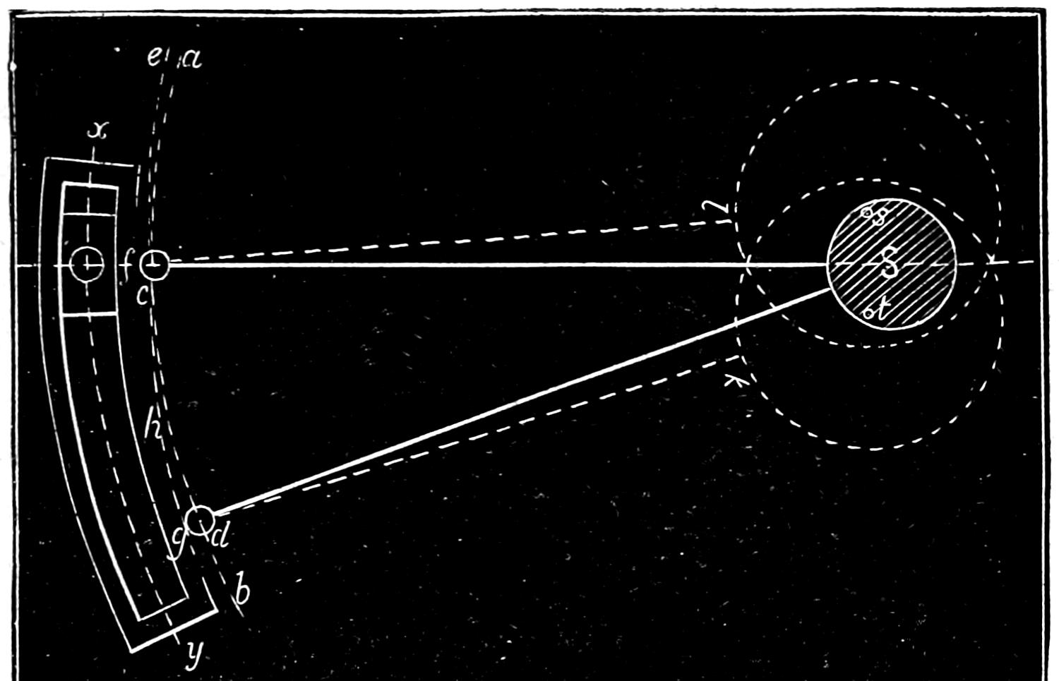
Fig. 129.
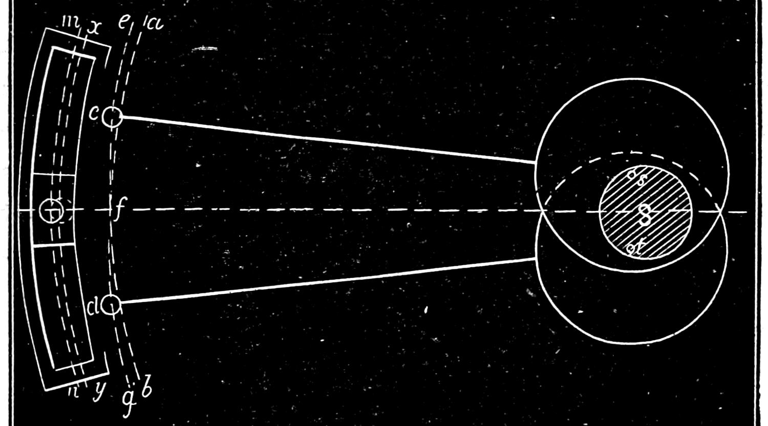
Fig. 130.
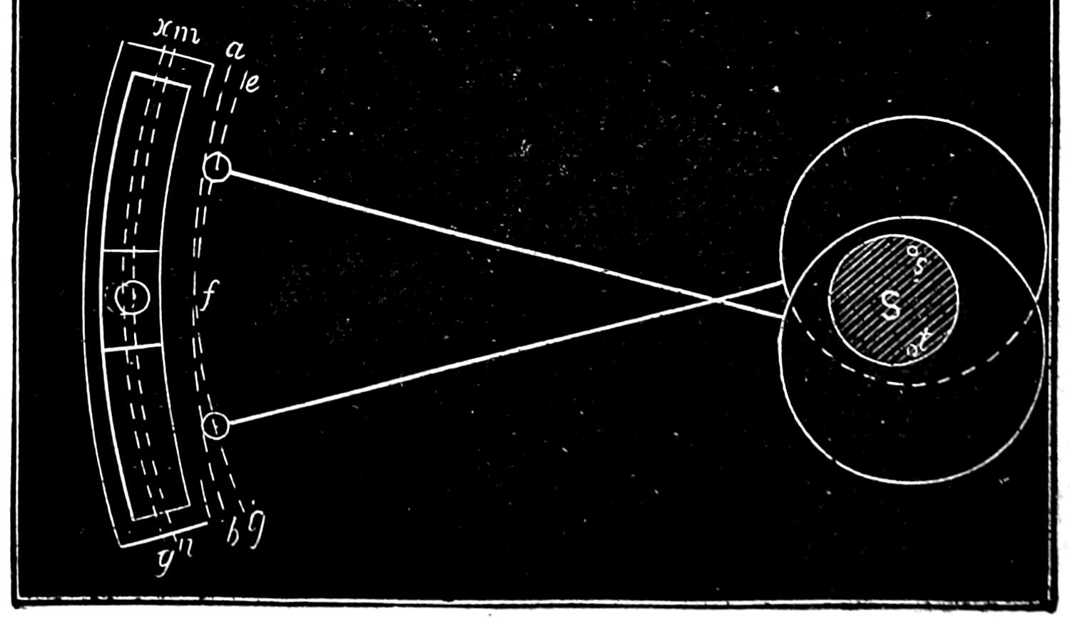
Fig. 131. Scale ³⁄₄ in. = 1 foot.
Question 200. What is the cause of this change of the amount of lead?
Answer. This can be best explained by reference to fig. 129, which represents a link with very short eccentric rods. If now the centre from which the link was drawn was in the centre of the axle S, and the eccentric straps embraced the axle instead of the eccentrics, their ends c and d would each describe the same arc, a b, parallel with the centre line, x y, of the link, and the latter could then obviously be raised and lowered without moving the rocker-pin at all. But the eccentric straps being attached to the eccentrics, as shown by the dotted lines, when the rods are raised or lowered they describe arcs, c e and g h, from the centres s and t of the eccentrics, and not from the centre of the axle. When the link is raised then, the end of the upper rod obviously moves in the arc c e, and the top of the link is moved from the axle, as shown in fig. 130, a distance equal to the interval between the arc, a b, drawn from the centre of the axle, and e f, which the rod describes from the centre of its eccentric. When the link is lowered from back to mid-gear, a similar action takes place, as the end, d, fig. 130, of the lower rod describes an arc, f g, so that the whole link is thrown from the axle a distance equal to the space between the arcs described from the centre of the axle and the centres of the eccentrics. When the position of the eccentrics is reversed, as shown in fig. 131, the link is moved towards the axle, thus causing an increase of lead on the opposite side of the valve. We have employed for our illustrations very short eccentric rods, in order to make this action apparent by exaggerating it. It is obvious from the engravings that the difference in the lead is increased as the eccentric rods are shortened, and also as the distance between the points of connection of the rods with the link is increased. It will also be plain that increasing the throw of the eccentrics, that is, increasing the distance of the centres s, s, of the eccentrics from the centre S of the axle will also increase the variation in the lead in full and mid-gear.
Question 201. What is meant by the distribution of steam in the cylinder?
Answer. It means the admission and exhaust of steam to and from the cylinder in relation to the stroke of the piston or the revolution of the crank.
Question 202. What are the principal periods or elements of the distribution of steam by the slide-valve and link motion?
Answer. They are:
1. The pre-admission or lead, that is, the admission of steam into the cylinders in front of the piston before it has completed its stroke.
2. The admission of steam after the piston has commenced its stroke.
3. The expansion of steam in the cylinder.
4. The pre-release, or exhaust of steam before the piston has completed its stroke.
5. The release, or exhaust during the return stroke of the piston.
6. The compression of steam, or closing the exhaust before the piston has completed its return stroke.
Question 203. What is meant by the clearance of the piston?
Answer. It is the space between the piston and the cylinder-head when the former is at the end of the stroke. If the piston touched the cylinder-head at the end of each stroke, it would cause a concussion or “thump” which would injure these parts. Owing to the impossibility of constructing machinery with absolute accuracy, it is therefore necessary to leave a space, usually from ¹⁄₂ to ¹⁄₄ in. wide, between the piston and the cylinder-heads, so as to be certain that they will not strike each other should there be any slight inaccuracies in the length of the piston-rods, connecting-rods, frames or other parts.
Question 204. Why is it desirable to open the steam-port and admit steam at the end of the cylinder towards which the piston is moving BEFORE the latter has completed its stroke?
Answer. Because it is essential, in order to insure a good action of the steam, that the maximum cylinder pressure should be attained at the very commencement of the stroke. If the steam-port was not opened until after the piston had commenced its stroke, some appreciable time would be consumed in filling the clearance space and the steam-way with steam.[57] It is also found, especially if an engine is working at a high speed, that a slide-valve worked by the ordinary link-motion will not open the steam-port rapidly enough to enable steam of the maximum boiler pressure to fill the space after the receding piston, unless the valve begins to open the port before the piston reaches the end of its stroke.
Another advantage resulting from the pre-admission of steam consists in the smooth working of the engine at high speeds, a circumstance which reduces greatly the wear and tear of the working gear. As the piston approaches the end of its stroke, the pre-admitted steam forms a kind of elastic cushion, which is well calculated to absorb the momentum of the reciprocating parts at that instant. The pressure due to the momentum of these parts will, of course, depend upon their weight and the speed of working, increasing directly as the square of the speed. It follows from this that the lead should increase with the speed, and that it should be greatest at high speeds. As has been shown before, this condition is fully accomplished by the ordinary shifting-link motion.
Question 205. Upon what does the admission of steam into the cylinder depend?
Answer. It depends in the first place upon the opening of the throttle-valve, and the size of the pipes and passages through which it is conveyed from the boiler to the cylinder. In the second place, it depends upon the time and amount of opening of the steam-port by the valve.
Question 206. What should be the pressure of the steam in the cylinder during admission?
Answer. In order that the steam may be used to most advantage, it should be admitted and maintained in the cylinder at full boiler pressure during the whole period of admission. If the opening of either the throttle-valve or the steam-ports is not sufficient to allow the steam to flow into the cylinder at full boiler pressure, the steam is said to be wire-drawn, and much of the advantage of using it expansively as has already been explained in answer to Question 59, is then lost.
Question 207. Why is it difficult to admit and maintain steam at the full boiler pressure in the cylinder during admission?
Answer. Because it is necessary to reduce the travel of the slide-valve in order to cut off the steam “short,” or soon after the beginning of the stroke of the piston. When the travel is reduced, the valve opens the port only a small distance, so that the area of the opening is not then sufficient to allow the steam to flow into the cylinder with sufficient rapidity to fill it at full boiler pressure, especially if the engine is working at a high speed. Thus, by referring to the table given on page 216 and to the motion curves in fig. 128, it will be seen that when the steam is cut off at from ¹⁄₄ to ¹⁄₂ stroke, the port is opened for the admission of steam only from ¹⁄₄ to ¹⁄₂ inch wide. From the curves it will also be seen that the valve then acquires its maximum travel and the steam-port its greatest width of opening very soon after the piston begins its stroke; after which the port is gradually closed, so that before the steam is entirely cut off the opening is so much reduced in area that the steam cannot flow through it rapidly enough to maintain the steam at full boiler pressure in the cylinder when the engine is working at high speeds.
Question 208. What means are used to overcome this difficulty and thus admit steam at full boiler pressure when the valve is cutting off short?
Answer. In the first place, the steam-ports are made from ten to twelve times as long as they are wide, so that a narrow opening will have a comparatively large area. In the second place, by giving the valve lead, not only are the clearance space and the steam-way filled with steam when the piston begins its stroke, but the port is then open a distance equal to the lead. With the ordinary link motion, as has already been shown, this lead increases as the travel and period of admission diminish, so that the smaller the total distance that the port is opened, the greater is its opening at the beginning of the stroke. As the steam is usually cut off short when locomotives run at high speeds, it will be seen that the increased lead which is imparted to the valve by the shifting link is an advantage rather than a disadvantage. But while it is often possible in this way to secure a pressure of steam in the cylinder at the beginning of the stroke equal or nearly so to that in the boiler, yet it is almost impossible to maintain this pressure during the whole period of admission, when the steam is cut off short and the engine working at a high speed. To obviate this evil what is called the Allen valve was designed, which is represented in fig. 132. This valve has a channel or supplementary port, a a, which passes over the exhaust cavity, and has two openings, b, b′, in the valve-face. When the valve begins to admit or “take” steam at c, as shown in fig. 133, it will be seen that it also uncovers the opening b′ at e and admits steam at b′, which passes through the channel b′ a a b and enters the steam-port c at b, and in this way there is a double opening for the admission of steam. The opening b of the supplementary port is closed as the valve advances, but when this takes place the steam-port is uncovered far enough to admit all the steam that is required. This form of valve is very efficient when the travel and point of cut-off are very short. It then gives just twice as much opening as the ordinary valve for the admission of steam. This improved valve has been much used in Europe; but, although it is an American invention, has not received the attention in this country which its merit deserves.
Fig. 132.
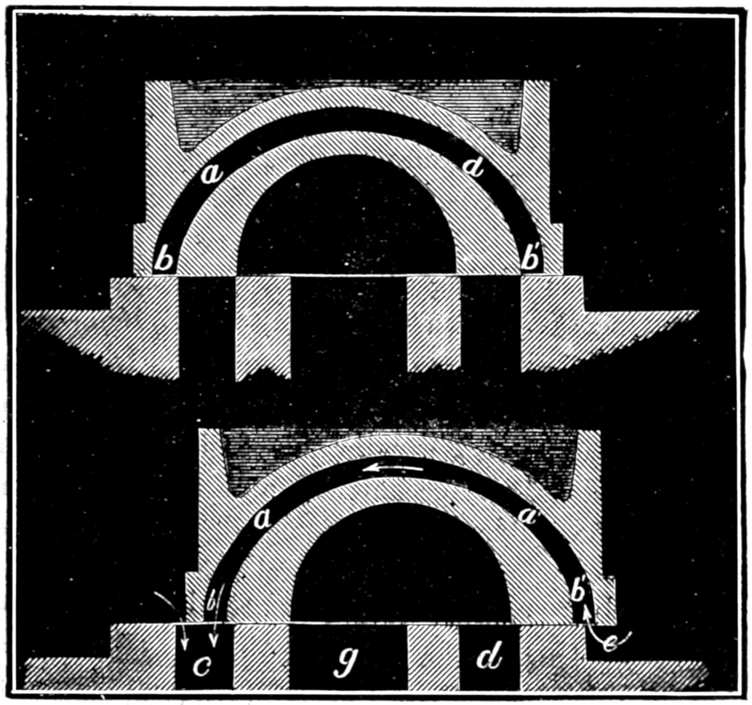
Fig. 133. Scale ³⁄₁₆ in. = 1 inch.
Question 209. What is meant by the pre-release of steam?
Answer. It is the release of the steam before the piston has completed its stroke. If it is confined until the piston has reached the end of the cylinder, there will not be time nor will it be possible, with a slide valve and link-motion, to secure a sufficiently large opening of the port to permit the steam to escape from the cylinder before the piston begins its return stroke. If there were no pre-release, there would therefore be more or less back pressure on the piston.
Question 210. Upon what does the amount of pre-release depend?
Answer. First, as has already been explained in answer to Question 51, on the amount of inside lap; and second, on the outside lap of the valve and lead of the eccentrics; and third, on the travel of the valve. The less the inside lap, the greater the outside lap and consequent lead of the eccentrics; and the shorter the travel of the valve, the earlier will be the release. The proper amount of this pre-release depends upon the velocity of the piston and the quantity of steam to be discharged or the degree of expansion. From the motion-curves in fig. 128 it will be seen that it is a marked feature of the shifting-link motion that the pre-release occurs earlier in the stroke as the link approaches mid-gear, or as the travel of the valve diminishes. As the link is usually worked near that position when the engine is run at a high speed, it will be seen that in this respect again the link-motion is well adapted for working the slide-valves of locomotives.
Question 211. What governs the period of release?
Answer. The release like pre-release is dependent upon the amount of inside lap, the outside lap and consequent lead of the eccentrics, and the travel of the valve.
The addition of inside lap has the effect of closing the port earlier than it would be closed without, and thus shortening the period of release and also of reducing the area of the opening of the port. This will be apparent by referring to fig. 128, in which the valve had ¹⁄₁₆ in. lead. The dotted lines which represent the edges of the ports in relation to the exhaust edges of the valve are therefore drawn ¹⁄₁₆ in. from the centre line a b. If, however, there had been no inside lap, then the edges of the ports would have conformed to the line a b. It will be observed that the first curve crosses the dotted line g g′ at 15¹⁄₂ in. of the forward stroke, which is the point at which the port is closed to the exhaust, or where the period of release ends and compression begins. If there had been no lap and the line g g′ had therefore occupied the same position as a b, then the motion-curve would not have crossed it until the piston had reached 16 in. of its stroke, thus showing that the period of release had been lengthened and compression delayed. As the width of the opening of the port is represented by the distance of the motion-curve from the right hand side of the line g g′, which represents the edge of the port, it is obvious that if there had been no lap, so that the position of the line representing the edge of the port had occupied the position of a b, then the space between it and the motion-curve would have been greater, thus showing that the port would have been opened wider if there had been no inside lap. The width of the opening of the port to the exhaust is in fact always diminished by an amount equal to the inside lap.
With the same travel, increase of outside lap and lead shortens the period of release, but has no effect on the width of the opening of the port to the exhaust.
Increase of travel, with the same outside lap, lengthens the period of release and also increases the width of the opening of the port to the exhaust.
Question 212. What governs the period of compression?
Answer. As compression begins when release ends, or when the port is closed to the exhaust, it is controlled by exactly the same causes, and as the two events occur simultaneously, of course whatever shortens the period of release lengthens that of compression.
Question 213. What effect do the clearance spaces and steam-ways have upon the compression of the confined steam?
Answer. By referring to the motion-curves in fig. 128, it will be seen that the steam-port is closed by the exhaust edge of the valve, or compression begins some time before the piston reaches the end of the stroke. The result is that the remaining portion of the cylinder, through which the piston must move after the port is closed to the exhaust, is filled with steam of atmospheric pressure, or possibly a little above that pressure. As this is confined in the cylinder, it is compressed by the advance of the piston. If there was no room between it and the cylinder at the end of the stroke, then either the cylinder would be burst or the valve would lift so as to allow the compressed steam to flow back into the steam-chest. The clearance and the steam-passages, however, afford considerable room, into which the confined steam can be compressed without danger of bursting the cylinder, or of raising the slide-valve when there is steam in the steam-chest. As the clearance spaces and steam-ways must be filled with high-pressure steam at the beginning of each stroke, it must be obtained either by taking a supply of “live”[58] steam from the boiler, or by compressing into the clearance spaces the low-pressure steam that still remained in the cylinder when the port was closed to the exhaust. By the latter process, a certain quantity of steam is saved at the expense of increased back pressure. It should be borne in mind also that the total heat of the compressed steam increases with its pressure, and as this latter approaches that in the boiler, the temperature of the former must have been raised from that due to about atmospheric pressure to nearer the temperature of that in the boiler. These changes of temperature which the steam undergoes will affect the surface of the metal with which the steam is in contact during the period of compression; it follows from this, that the ends of the cylinder principally comprising the clearance spaces must acquire a higher temperature than those parts where expansion only takes place. This is an important consideration, since the fresh steam from the boiler comes first in contact with these spaces, and by touching surfaces which have thus previously been heated, as it were, by the high temperature of the compressed steam, less heat will be abstracted from the fresh steam, and therefore a less amount of water will be deposited in the cylinder.[59]
It will thus be seen that the effect of compression is to fill the clearance spaces and steam-ways with compressed steam before pre-admission begins. As already stated, this is done at the expense of back pressure in the cylinder. It must be remembered that all the energy, excepting that part which is wasted by loss of heat, friction, etc., which is consumed in compressing the confined steam, is again given out to the piston by expansion. The confined steam also acts as an elastic cushion to receive the piston, just as the steam which is admitted before the end of the stroke would if there were no compression. Compression, therefore, has the effect of saving the quantity of live steam which it would otherwise be necessary to admit before the end of the stroke to fill the clearance spaces and steam-ways and also to “cushion” the piston. As already stated, the momentum of the piston and other parts depends upon their weight and the speed at which they are working, increasing directly as the square of the speed, from which it follows that the compression should increase rapidly with the speed, and should be the greatest at high speeds. As the ports are prematurely closed to the exhaust with the shifting-link motion, and as the lead increases rapidly as the link approaches mid-gear, and the amount of compression is at the same time correspondingly augmented, it will be seen that the shifting-link motion fulfills these conditions very perfectly.
The pressure to which the confined steam will rise depends of course upon the amount of the period of compression, and also on the size of the clearance spaces. As it is possible to have such an amount of compression that it will exceed the boiler pressure, and thus raise the valve from its seat and be forced back into the steam-chest, some care must be exercised to proportion the one to the other, so that the degree of the confined steam may not be excessive.
Question 214. How can the effect of the distribution of the steam upon its action in the cylinder be determined by experiment?
Answer. As already explained in answer to Question 55, this can be done by an instrument called a steam indicator.
Fig. 134.
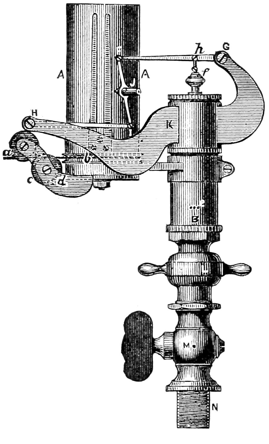
Fig. 135.
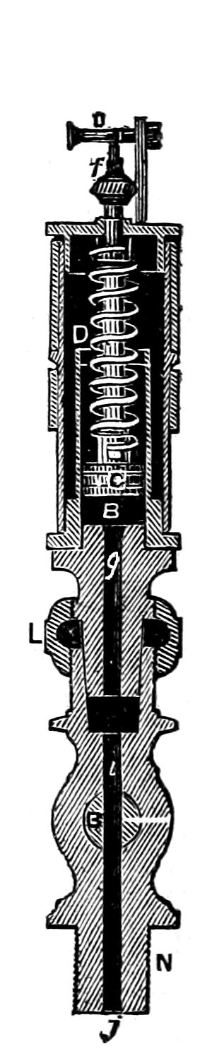
Scale 3 in. = 1 foot.
Question 215. What is the construction of this instrument?
Answer. The indicator now ordinarily used is the Richards indicator, the outside of which is represented in fig. 134 and a section in fig. 135. It consists of a cylinder, B, into which a piston, C, is accurately fitted, but so that it will move freely in the cylinder. The piston rod is surrounded with a spiral spring, D, the lower end of which is attached to the top of the piston, and the upper end to the cylinder cover. When steam is introduced below the piston it pushes it up in the cylinder and the spring is compressed. If there should be a vacuum below the piston, the air above it will press the piston downward and extend the spring. This latter occurs only when the indicator is used on condensing engines. Of course the distance which the piston is forced up by the steam pressure below it depends upon the amount of pressure and also on the tension of the spring; and therefore by attaching a pencil to the piston-rod so that it can mark on a moving card in front of it, a diagram will be drawn which would indicate the steam pressure, as was explained in answer to Question 55. But there are some practical difficulties in the way of doing this. It is found that if the pencil is attached directly to the piston-rod of the indicator, the distance through which they must move, in order to make the scale of the diagram sufficiently large to be clear, is so great that the momentum of the parts carries them further than the pressure of the steam alone would move them. The distance through which the pistons or instruments move, moreover, makes it impossible that the changes of pressure should be indicated simultaneously with the position of the piston; the latter must travel while the action is taking place, and thus the diagram shows changes of pressure later or more gradually than they occur.[60] To overcome these and other difficulties, the piston-rod of the indicator which we have illustrated is attached at h to the short arm of a lever, F G, and to the end of the long arm a piece, F I, is attached, which carries a pencil, J. By this means the piston has only one-fourth of the motion that it imparts to the pencil, so that the momentum of the moving parts is comparatively slight. If the pencil was attached directly to the end of the lever, it is obvious that it would move in the arc of a circle, and that this would be a source of error in the diagram. To avoid this the pencil is attached to what is called a “parallel motion.” This consists of a coupling-rod, F I, which connects the ends of two levers, F G and I H. The centre of the rod F I, to which the pencil is attached, will with this arrangement move in a straight line. The levers and all the parts are of course all made as light as possible, so that their weight will have little effect on the motion of the indicator piston.
The paper or card on which the diagram is drawn is wrapped around a brass cylinder, A A. This cylinder is made to revolve part of the way around by a strong twine, a b, which is wrapped around a pulley, b, at the bottom of the cylinder. The twine is attached to a lever, similar to that shown in fig. 30, which receives a reciprocating motion from the piston of the engine. The twine can of course move the cylinder only in one direction, and therefore a coiled spring similar to a clock spring is placed inside of the cylinder to draw it back when the twine is relaxed. In this way the paper cylinder or drum receives a part of a revolution at each stroke of the piston, and moves simultaneously with it. This drum is used instead of a flat card, on account of the practical difficulties of employing the latter. The motion of the paper on this drum will, however, be exactly the same in relation to the pencil as the motion of a flat card would be.
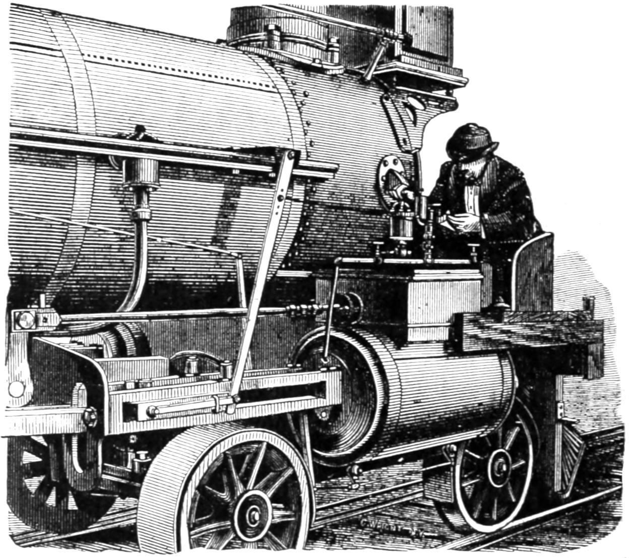
Fig. 136a.
The method of attaching an indicator to a locomotive is represented in fig. 136a. It will be seen from this that it is placed over the center of the steam chest and connected to each end of the cylinder with ³⁄₄-inch pipes. A globe valve was in the case represented placed on each side of the indicator, so that it could be put into communication with either end of the cylinder, or could be completely shut off from both. A better plan, however, is to have a three-way cock at the point where the horizontal pipe connects with the vertical one leading to the indicator, as the passages in a three-way cock are more direct than those in globe valves. The arrangement of the levers for giving motion to the indicator drum, and of the seat, which is very requisite for the experimenter, will be readily understood from the engraving without further explanation. It is thought by some engineers that the indicator should be applied as near to each end of the cylinder as possible. It is believed, however, that if the pipes, cocks, and their connections are made large enough so as not to impede the motion of the steam, no appreciable error will arise from the method illustrated in fig. 136a.
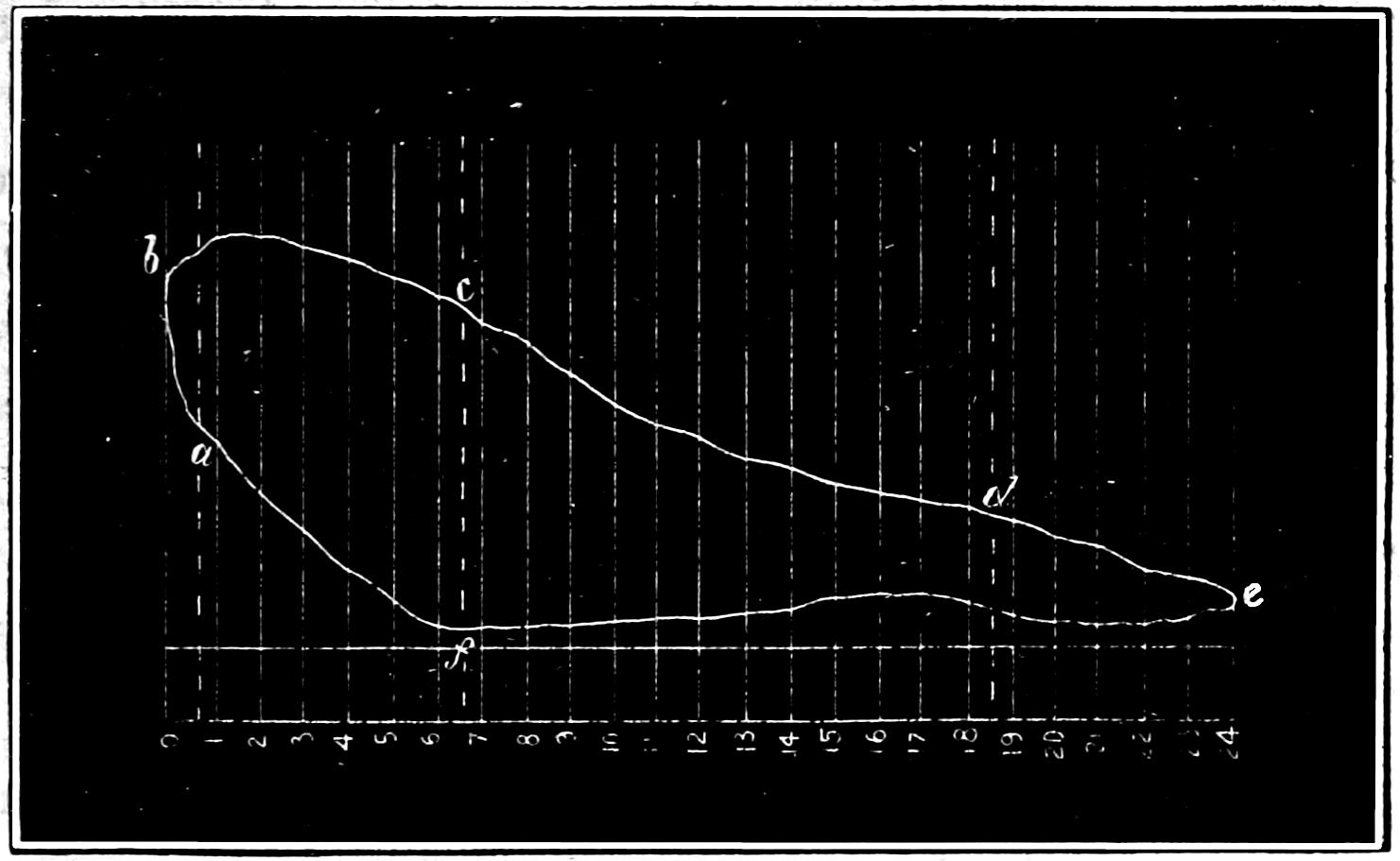
Question 216. What should be the form of an indicator diagram, if the steam is distributed by a link motion so as to produce the best practicable action in the cylinders?
Answer. It should approximate to that shown in fig. 136b. In this diagram the vertical lines represent inches of the stroke, and the scale on the left the steam pressure in pounds per square inch. The atmospheric and vacuum lines are also indicated, as already explained in answer to Question 55. The points at which the different periods of the distribution begin are indicated by the letters a, b, c, d, e and f. These are in the order in which they occur: a, pre-admission; b, admission; c, expansion; d, pre-release; e, release; and f, compression. The lines forming the outline of the diagram will be designated for convenience of description as follows:
The line from a to b, the admission line.
The line from b to c, the steam line.
The line from c to d, the line or curve of expansion.
The line from d to e, the exhaust line.
The line from e to f, the line of back pressure.
The line from f to a, the line or curve of compression.
Fig. 136b.
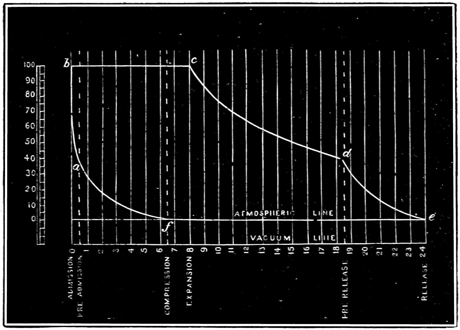
The diagram represents a distribution of steam produced by a valve having ⁷⁄₈ in. outside and ¹⁄₁₆ inside lap, and operated by the link motion represented in fig. 103. The eccentrics have 5 in. throw, and the steam-ports are 1¹⁄₄ and the exhaust 2³⁄₄ in. wide. The valve as shown by the diagram is cutting off at 8 in., or one-third of the stroke. Pre-admission begins when the piston still has ¹⁄₂ in. to move before reaching the end of its stroke. Admission of course begins with the stroke, expansion at 8 in., pre-release at 18¹⁄₂ in., release at the end of the stroke, and compression at 17¹⁄₂ in. of the return stroke. The valve is supposed to be set without any lead, or “line and line,”[61] as it is called at full stroke. When the steam is cut off at 8 in. of the stroke, the valve has 2⁵⁄₈ in. travel and ³⁄₁₆ in. lead. The steam pressure in the boiler is supposed to be 100 pounds above the atmosphere. Of course, when the valve cuts off at different points of the stroke, the periods of distribution will be somewhat changed; but from the above diagram the principal features of a good distribution can be explained.
These are: First, that the steam pressure should rise rapidly during the period of pre-admission, so that there will be full boiler pressure in the cylinder at the beginning of the stroke. When this occurs, the pre-admission line will rise from a to b, to such a point at b which will indicate full boiler pressure in the cylinder. The same pressure should then be maintained in the cylinder during the whole period of admission, and the admission line from b to c should therefore be a straight horizontal line, as shown in fig. 136b. When expansion begins, the pressure will fall, as was explained in answer to Question 55. The expansion line should approximate a hyperbolic curve, but if there is much loss of heat by radiation or other causes, the diagram will fall considerably below the theoretical curve. With cylinders well protected and with dry steam the expansion line will fall slightly below a hyperbolic curve at the beginning of the period of expansion, and rise above it during the latter part of the same period. The reason of this is that the cylinder is heated by the admission of live steam of comparatively high pressure and temperature, so that, when the pressure becomes reduced by expansion, a part of the water which is condensed in the cylinder will be re-evaporated by the heat in the latter. From the point of the pre-release, d, to the end of the stroke, e, the exhaust line should fall rapidly, so that there will be no pressure behind the piston during its return stroke. To explain the theoretical form of the exhaust line would lead us into a very abstruse discussion, which would be out of place here. It will be sufficient for our purpose to call attention to the fact that the pre-release should allow all the steam in the cylinder to escape before the piston reaches the end of the stroke, so that the back pressure during the return stroke may be as low as possible. It is, however, only at comparatively slow speeds that the steam in locomotive cylinders escapes during the period of pre-release, so that the back pressure is reduced to that of the atmosphere. It is necessary in locomotives, as has already been explained, to contract the area of the blast orifices or exhaust nozzles, in order to stimulate the draft through the fire, so that the steam cannot escape with sufficient rapidity to reduce the back pressure to that of the atmosphere if the engine is running fast. Of course every pound of back pressure on the piston is so much loss of energy, and a reduction of the amount of work done by the engine; but it is a sacrifice which must be made in order to be able to generate the requisite quantity of steam. In studying the distribution of steam, however, every effort should be made to reduce the back pressure as much as is practicable, and yet maintain a sufficient supply of steam, and therefore the line of back pressure should conform as closely as possible to the atmospheric line. The compression line should be a hyperbolic curve, beginning with the period of compression. In calculating both the compression and expansion, allowance must be made for the clearance space and steam-way. In a cylinder like that illustrated in fig. 92, their contents would be about equal to that of two inches of the cylinder. Therefore, when steam is cut off at 8 in. of the stroke, instead of having a quantity of steam which will fill a cylinder 16 in. diameter and 8 in. long, we have as much as would fill a cylinder of that diameter and 10 in. long. The same thing is true of the compression. This must occur in the above example when the piston has 6¹⁄₂ in. more to move before completing its stroke. There is therefore a quantity of steam in front of it sufficient to fill a cylinder 8¹⁄₂ in. in diameter. This steam is of course compressed by the advance of the piston, and if its pressure when compression begins is the same as that of the atmosphere, then it will be 0.9 lbs. above it when the piston has only 6 in. to move and 3.2, 6.2, 10.5, 16.9, and 27.5 lbs. effective pressure when the piston has 5, 4, 3, 2 and 1 inches to move respectively, and when pre-admission begins, the pressure will have risen to 48.7 lbs. If the back pressure is above that of the atmosphere, of course the compression will be correspondingly increased. It will also be seen that, without any or with very little clearance space, the compression would at the end of each stroke rise above the boiler pressure. It being a peculiarity of the ordinary shifting-link motion that as the period of admission is reduced that of compression is lengthened, the latter becomes very excessive when the steam is cut off at less than one-third or one-fourth of the stroke.
Question 217. In what respect would a diagram made by an indicator differ from the theoretical form represented in fig. 136b?
Answer. It would be drawn with less exactness; that is, the corners instead of being sharply defined, as in fig. 136b, would be more or less rounded, as in fig. 137, and the curves and straight lines would vary somewhat from the exact mathematical form indicated in fig. 136b. The higher the speed at which the engine is working when the diagrams are taken, the greater will be the variation from the theoretical form.
Fig. 137.
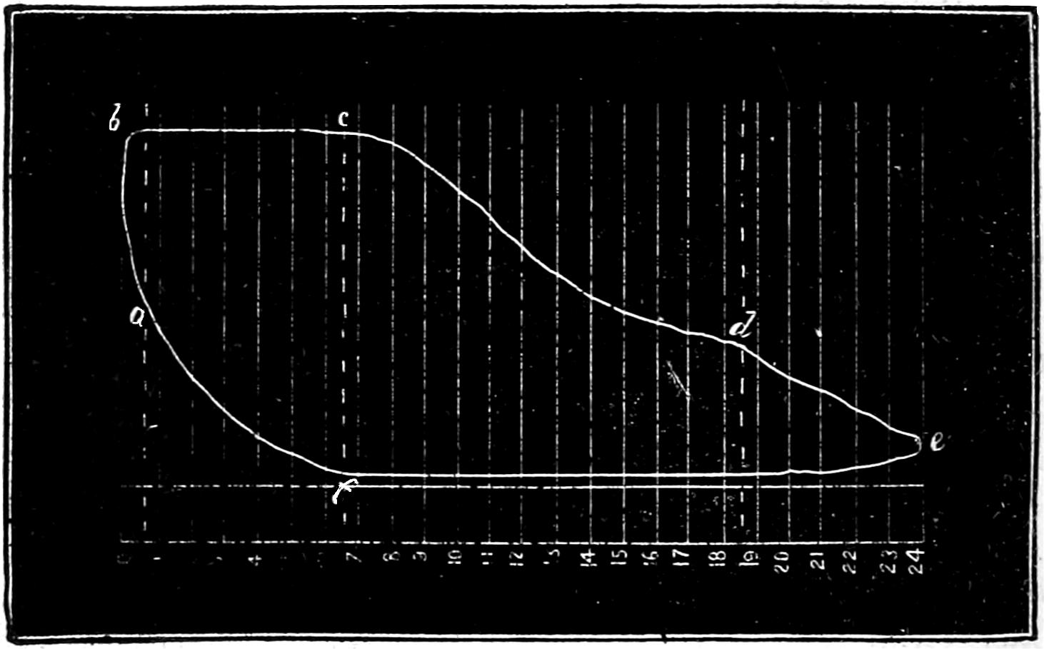
Question 218. If the amount of pre-admission is insufficient, how will it be shown in the indicator diagram?
Answer. The effect of too little pre-admission is to lower the pressure of the steam at the beginning of the stroke, and at high speeds there will not be time enough nor sufficient opening of the steam-port to supply the deficiency after the stroke has commenced. The corner of the diagram at b will then be very much rounded, as shown in fig. 138. This is apt to be the case when steam is admitted during a considerable part of the stroke, as a shifting-link motion then gives less lead than when it is worked nearer mid-gear. If the steam is cut off short, then the pressure in the cylinder during admission is very much below boiler pressure, and is apt to fall rapidly after the commencement of the stroke, as shown in fig. 138.
Fig. 138.
Question 219. If the opening of the steam-ports during admission is too small, what will be the form of the diagram?
Answer. The effect will be very much the same as that produced by too little pre-admission or lead; that is, the pressure in the cylinder will be much lower than in the boiler and will fall rapidly during the periods of admission, as shown in fig. 138.
Question 220. What defects will be indicated by the expansion curve of indicator diagrams?
Answer. If the cylinders are not well protected, and there is much loss of heat from radiation, there will be a rapid fall of pressure during the period of expansion, which will be shown by the expansion curve falling below the theoretical curve shown in fig. 136b. If, on the contrary, the indicator curve is much above the theoretical curve, it may be caused by a leak in the valve. As steam is quite as likely to leak from the steam-port into the exhaust as from the steam-chest into the steam-port, a valve which is not tight may produce just the contrary effect upon the indicator diagram. As it is usually quite easy to detect a leak in the valve by other means, the use of the indicator for this purpose is unnecessary. Attention is called to it, however, to show the impossibility of getting results of any value with the indicator if the valves are not steam-tight.
Question 221. What should be observed regarding the exhaust line of the indicator diagram?
Answer. The most important point to be observed is, whether the pressure at the end of the stroke is reduced as low as possible, as at high speeds it is usually much more difficult to exhaust the steam from than to admit it into the cylinder. As already stated, the blast in the chimney makes it almost impossible to exhaust the steam to atmospheric pressure when the locomotive is running fast. If the steam is released too late in the stroke, as already explained, there will not be time enough nor sufficient opening of the port to allow the confined steam to escape from the cylinder before the end of the stroke, and this will be indicated on the diagram by the space between the line of back pressure and the atmospheric line during the commencement of the return stroke, as shown in fig. 138.
Question 222. What should be observed regarding the line of back pressure?
Answer. The most important point is, that it should approximate as closely as possible to the atmospheric line, as all the back pressure not only diminishes the efficiency of the engine, but is a total loss of energy. Too much inside lap will increase the amount of back pressure, but generally it is more influenced by the area of the blast orifices than by any other cause. Every effort should be made, therefore, to have them as large as possible and yet have the boiler make as much steam as is needed.
When only one blast orifice is used for both cylinders, it often happens that when the steam is exhausted from the one cylinder it “blows” over into the other, and thus produces an additional amount of back pressure. This is shown by a rise or “hump” in the line of back pressure, as indicated in fig. 138.
Question 223. Can the amount of compression which is needed be determined by calculation?
Answer. Yes; but it involves more abstruse principles of mathematics than it is thought best to introduce here. Some of the reasons can, however, be given, which will make the subject clearer, and enable the reader, if he has sufficient knowledge of mathematics, to investigate the subject still further.
Fig. 140.
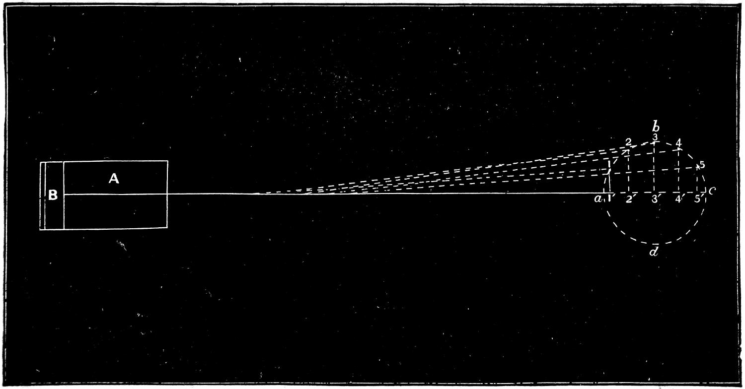
In the first place it is a well-known fact that the motion of a piston in the cylinder of a steam engine is not a uniform one, but increases in speed from the beginning of the stroke to the middle, and diminishes in speed from the middle to the opposite end. The cause of this is that the crank revolves at a uniform speed during the entire revolution, but the piston moves much less at the beginning of the stroke, with a given amount of revolution of the crank, than it does at the middle. This is shown in fig. 140, in which A is a cylinder and B the piston and a b c d the path of the crank. Now while the crank moves from a to 1, or ¹⁄₁₂ of a revolution, the piston has moved 1³⁄₈ in., or a distance equal to that from a to 1′ or to the base of a perpendicular drawn from 1 to the centre line a c. While the crank moves from 1 to 2, or through the second twelfth of a revolution, the piston has moved from 1′ to 2′, or 4³⁄₈ in., or 2³⁄₄ in. further than during the first twelfth of the crank’s revolution. During the third twelfth of the revolution the piston moves from 2′ to 3′, or 6 in., thus showing that it continues to increase in the distance moved during each period of the revolution of the crank until the latter has made a quarter revolution. The speed of the piston then begins to diminish until it reaches the end of the stroke. It is slightly affected by the angularity of the connecting-rod, as already explained, but for the present this is disregarded. It is obvious now that if the momentum, or actual energy stored up in the piston and other reciprocating parts after they have passed the middle of the stroke, added to the pressure behind the piston, is greater than the resistance offered by the crank, the motion of the latter will then be accelerated and thus conveyed to the moving engine and train. If, however, there is any momentum in the piston when it reaches the end of the stroke, evidently it can exert no power to cause the crank to revolve, but must be expended by producing a pressure on the crank-pin and thus on the axle-boxes. Not only will such a pressure not cause the crank to revolve, but it will be more difficult to turn the crank with such a pressure against it than it would be without. The momentum of the piston and other reciprocating parts at the dead point therefore creates a resistance to the movement of the crank instead of helping to turn it. It will also be observed that after the crank has moved slightly from the dead point, any pressure on the piston will exert very little force which will tend to turn the crank. In fact the nearer the piston is to the end of the stroke the greater is the proportion which the friction of the crank-pin and axle bears to the useful effect of the strain in causing the crank to turn. Calculation shows that for about three degrees on either side of the dead points the effect of pressure on the crank-pin is actually to retard the engine. If now the piston reaches the end of the stroke with a certain amount of unexpended momentum stored up in it, if this energy is expended by producing pressure on the crank, then it will not only be a waste of energy but a double waste by retarding the motion of the crank. If, however, this energy can be absorbed by compressing steam which will fill the clearance spaces, it will not only prevent the retarding effect referred to, but the energy in the piston and other parts will be converted into steam pressure, which will be given out in useful work during the next stroke. It would, of course, be impossible to arrest the motion of the piston instantly, and therefore its momentum is gradually absorbed from the time compression begins until it reaches the end of the stroke. As the energy of a moving body is equal to its weight multiplied by the square of its speed, it is obvious that to overcome this a different amount of compression would be required for each speed, and also that it must be adjusted to the weight of the moving parts. Such exact adaptation is not practicable on locomotives, nor does the link motion enable us to alter the amount of compression with so much exactness: but the explanation shows the value of increasing the amount of compression with the speed, which fortunately the peculiarities of the shifting-link motion enable us to do without difficulty.
Fig. 139.
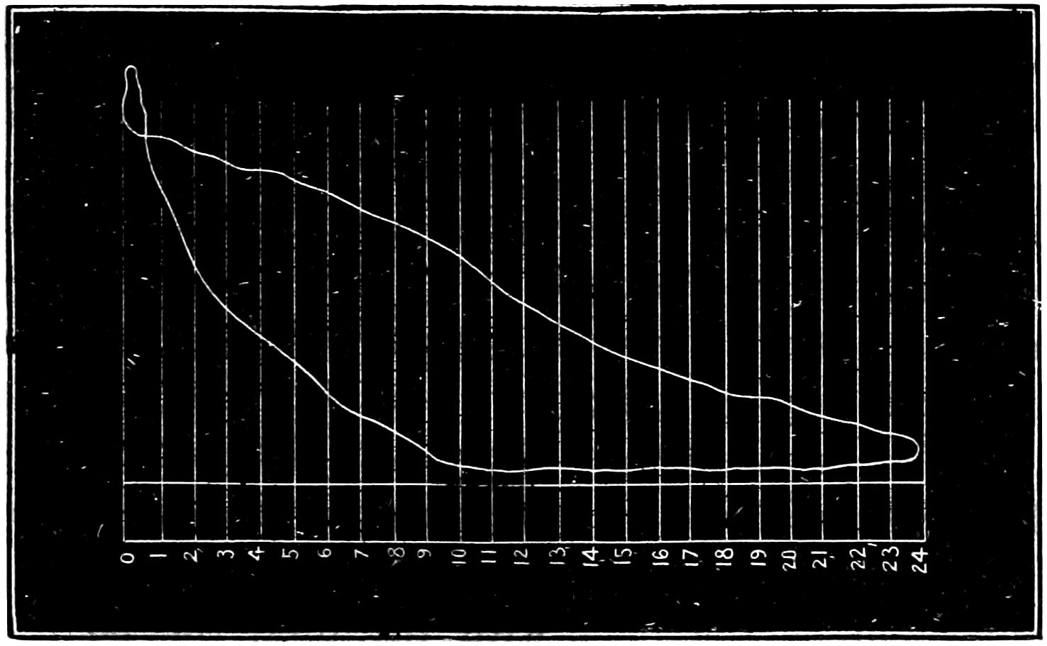
Question 224. What cause produces the form of diagram represented by Fig. 139?
Answer. It is produced by excessive compression, which causes the pressure in the cylinder to rise above boiler pressure before pre-admission begins. As soon as the port is opened, part of the steam in the cylinder flows back into the steam-chest, and thus the pressure is reduced, as shown by the diagram.
Question 225. How can we determine whether the steam is distributed in the cylinders to the best advantage, and how can we discover the fault, if there is one, in the link motion?
Answer. The indicator will show the action of the steam in the cylinder, and motion-curves drawn with the instrument described in answer to Question 192 will show the exact movement of the valve. By comparing the indicator diagram with the motion-curves, the one will show the defects in the other.[62]
Question 226. To what extent can the movement of the valve be modified by alterations in the proportions of the link motion?
Answer. The motion of the valve is susceptible of an almost infinite number of changes, by different variations and combinations of proportions of the working parts of the link motion. These changes are, however, limited by the general laws which govern the motion of eccentrics, and therefore cannot influence the motion of the valve beyond certain limits. Hardly any variation can be made either in the proportions or arrangement of the working parts which will not have some influence upon the movement of the valve. Aside from the proportions of the valve itself, which have already been discussed, the throw of the eccentrics, the length of the rods and of the link, the point of connection of the rods with the link, the point of suspension, the position of the lifting shaft, the length of the arms, the length and position of the rocker arms will each of them effect the distribution of steam. The number of combinations of all these different proportions is of course almost infinite, and therefore any full discussion of them will be impossible here.
Question 227. What are the most important points which require attention in designing a link motion?
Answer. It should be proportioned so that—
First, the lead and the period of admission should be the same for each end of the cylinder, for each point of cut-off, and, if possible, in back as well as forward gear.
Second, the width of opening for both admission and exhaust should be as large as possible when steam is cut off short.
Third, the exhaust or pre-release should occur early enough and be maintained long enough to reduce back-pressure as low as possible.
Question 228. How can the lead and period of admission be equalized?
Answer. It is impossible to make the periods of admission absolutely alike for every point of cut-off in both fore and back gear. It is therefore customary to disregard the back gear, as engines are worked but little with the link in that position. Even for forward gear the periods of admission cannot be made exactly alike for each end of the cylinder and for each point of cut-off, and therefore it is usual to make the periods of admission alike for half-gear forward, in which position the link is worked most.
The periods of admission for the front and back ends of the cylinder can be changed most in relation to each other by altering the position of the point of suspension on the link. This can be done either by moving this point up or down, or horizontally. Usually links are suspended from a point halfway between the points of connection of the eccentric-rods and from ¹⁄₄ to ³⁄₄ in. back of the centre line of the slot in the link. A somewhat better distribution can be secured by suspending it about 3 in. above the centre, but the suspending link must then be made so short that it is subjected to very great strains by the motion of the link, and this evil is usually considered much greater than the advantage which is gained thereby in the more equal distribution. The point at which the upper end of the suspension link is hung also influences the relative amount of admission front and back. This point, of course, varies as the end of the lifting arm is raised or lowered. In designing valve gear it is usually tested by a full-sized model, which will show the exact motion of all the parts. The best position for the lifting shaft and the length of its arm can be determined perhaps most satisfactorily by placing the link in full gear forward, then moving the point of suspension of the upper end of the link-hanger horizontally so that the front and back admission will be alike, and then marking this position. The same process should then be repeated for half gear and for the shortest point of cut-off. If the position of the lifting shaft and the length of its arm are then so arranged that the end of the latter will move through the three points which have been thus determined, the admission will be very nearly equal for each end of the cylinder. Usually, however, it is impossible to arrange the shaft and arm so that they will conform exactly to these conditions, and therefore an approximation is made which will come as near as possible to what is required. It may be stated, however, that the lifting shaft should be kept as low as possible, so as not to interfere with the eccentric-rods. In some cases the shaft has been suspended from the boiler, so that the outside eccentric-rod would work past or over the end of the lifting shaft, thus allowing the latter to be located lower than would otherwise be possible.
Question 229. Which parts of the link-motion have the greatest influence on the distribution of steam?
Answer. The lap of the valve and the throw of the eccentrics. The effect of any change of these upon the distribution is very similar to that produced if a single eccentric is used, which was explained in the answers to Questions 49, 50 and 52.
Fig. 141.
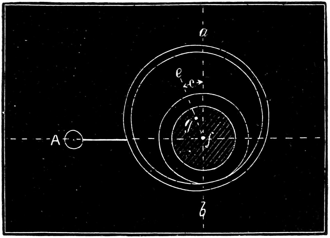
Question 230. What is the effect upon the admission of increasing the throw of the eccentrics with the same lap?