PART XI. THE VALVE-GEAR. (continued 2)
Reading edition
Answer. As already explained, the effect is to increase the period of admission, or in other words to cut off later in the stroke, and also to increase the width of the opening of the steam-port or the distance which the valve throws over the port. This has an important influence upon the admission, when the link-motion is used.
Question 231. What is meant by the angular advance of the eccentrics?
Answer. It is the angle which a line, e f, fig. 141, drawn through the centre of the axle and the centre of the eccentric makes with a vertical line a b, when the crank is on one of the dead-points or centres. Thus in fig. 141 the crank A is represented on the front centre. In order to give the valve the necessary lead the eccentric must be moved ahead of the vertical line a b. The angle c which the line e f (drawn through the centre of g of the eccentric and f of the axle) makes with the vertical line is called the angular advance.
Question 232. What is meant by linear advance?
Answer. By linear advance is meant the distance which the valve has moved from its middle position at the beginning of the stroke of the piston. This, when the two rocker arms are the same length, is the same as the distance of the centre of the eccentric g from the vertical line a b, fig. 141.
Question 233. Why does the cut-off occur earlier with an eccentric having a short throw than with one which gives more travel to the valve?
Answer. Because it is necessary to give the eccentric with the short throw more angular advance in order to give the valve the required lead. This is illustrated in fig. 142, in which a section of a valve, V, and ports c, g, and d, are represented. In order to simplify the diagram as much as possible the rocker is left out and the valve is supposed to be moved by the rod R directly from the centre a of the eccentric.[63] The effect of the angularity of the connecting rod and eccentric rod is also neglected. The circle a b e f represents the path of the centre of an eccentric having 5 in. throw, and h i j the path of one having 3¹⁄₂ in. throw. In order to give the valve the required lead, which is supposed to be just line-and-line at the beginning of the stroke, the linear advance of the valve must be equal to the lap, or ⁷⁄₈ in. If therefore we draw a line, p a, parallel to the vertical centre line, e k, and ⁷⁄₈ in. from it, the intersection of p a at a and h with the paths of the eccentric will be the centres of the eccentrics. If through these centres and the centre of the circle, lines, o a and o p, be drawn, the angles which they make with the vertical e k will be the angular advance. It will be seen from these lines that in order to give the valve the required lead it is necessary to give the eccentric with the small travel more angular advance than is necessary for the one with the larger throw. It is obvious, too, that when the centre of the larger eccentric has reached the point b the valve will have received its greatest travel, and that when it reaches p the steam-port c will again be closed or the steam cut off. If the small eccentric is employed, the valve will then have its maximum travel when the centre h reaches s, and the port will be closed when it reaches i. By drawing lines, o p and o n, through i and p, it will be seen that from the beginning of the stroke until the steam is cut off, if the large eccentric is employed, it, and consequently the shaft and crank, must move over an angle measured by the arc q t p. If the small eccentric is used, it and the crank must move through an angle measured by the arc u t n. In other words, the crank must turn a considerably greater distance before steam is cut off with an eccentric having a large than with one having a small throw.
Fig. 142.
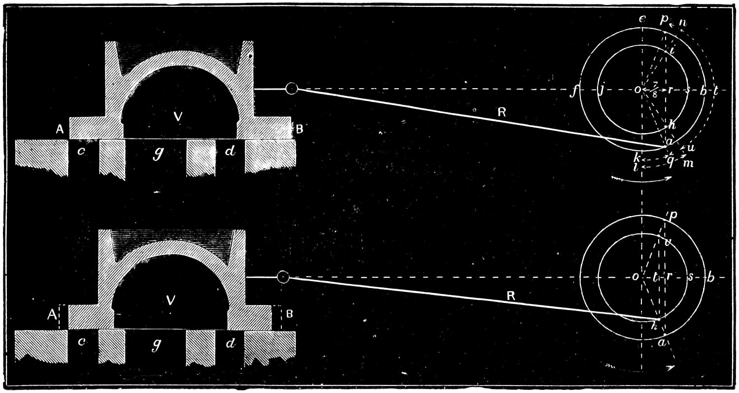
Fig. 143. Scale ³⁄₁₆ in. = 1 inch.
It is also quite obvious from fig. 142 why the port is opened a shorter distance with a small than with a large eccentric. The distances o s and o b are equal to half the throws of the eccentrics, or 1³⁄₄ and 2¹⁄₂ in. The linear advance o r is in both cases ⁷⁄₈ in., and therefore after the port begins to open the valve will be moved by the small eccentric a distance which is equal to 1³⁄₄ - ⁷⁄₈ = ⁷⁄₈ in., and by the large one 2¹⁄₂ - ⁷⁄₈ = 1⁵⁄₈ in.
Fig. 144.
Scale ³⁄₁₆ in. = 1 inch.
Question 234. What is the effect on the admission of giving an eccentric with a small throw the same angular advance as one with a large throw, and then reducing the lap of the valve so that the lead will be the same in both cases?
Answer. The admission and the cut-off will then occur at the same points of the stroke, but the ports will not be opened so wide. This is illustrated in fig. 143, in which the paths of two eccentrics having the same throw as those in fig. 142 are represented. The centre, a, of the larger eccentric is represented in the same position in fig. 143 as in fig. 142. If a line is drawn from the centre of the larger eccentric to that of the axle, and if the centre, h, of the smaller eccentric is located on the intersection of this line with the circle representing its path, then the smaller eccentric will have the same angular advance, but the linear advance measured by the distance o t will be only ⁵⁄₈ in. If the valve have the same lap as in fig. 142, its steam edges at the beginning of the stroke, if the small eccentric is employed, will occupy the position represented by the dotted lines A and B. If these edges are cut off, as shown by the full lines and shading, then the valve will have the same lead as in fig. 142. It is obvious, too, that if the smaller eccentric has the same angular advance it will reach the point v, at which, with the reduced lap, the steam will be cut off, at the same time that the centre, a, of the large eccentric will reach p, at which point it cuts off the steam with the valve having the large lap. There is, however, this difference in the distribution, that in the one case the valve opens the port a distance equal to t s, and in the other a distance equal to r b. As o t is equal to the linear advance of the small eccentric, or ⁵⁄₈ in., and o s to half the throw of the eccentric, or 1³⁄₄, t s is equal to 1³⁄₄ - ⁵⁄₈ = 1¹⁄₈ in. The distance r b, as shown above, is equal to 2¹⁄₂ - ⁷⁄₈ = 1⁵⁄₈ in., so that the effect produced upon the admission of using an eccentric with a small throw and corresponding amount of lap is, that the ports are not opened so wide as with an eccentric having a larger throw.
Fig. 145.
Scale ³⁄₁₆ in. = 1 foot.
Question 235. How do eccentrics with a short throw, and valves with a corresponding amount of lap, affect the admission with a link motion as compared with eccentrics having a larger amount of throw and greater lap of valve?
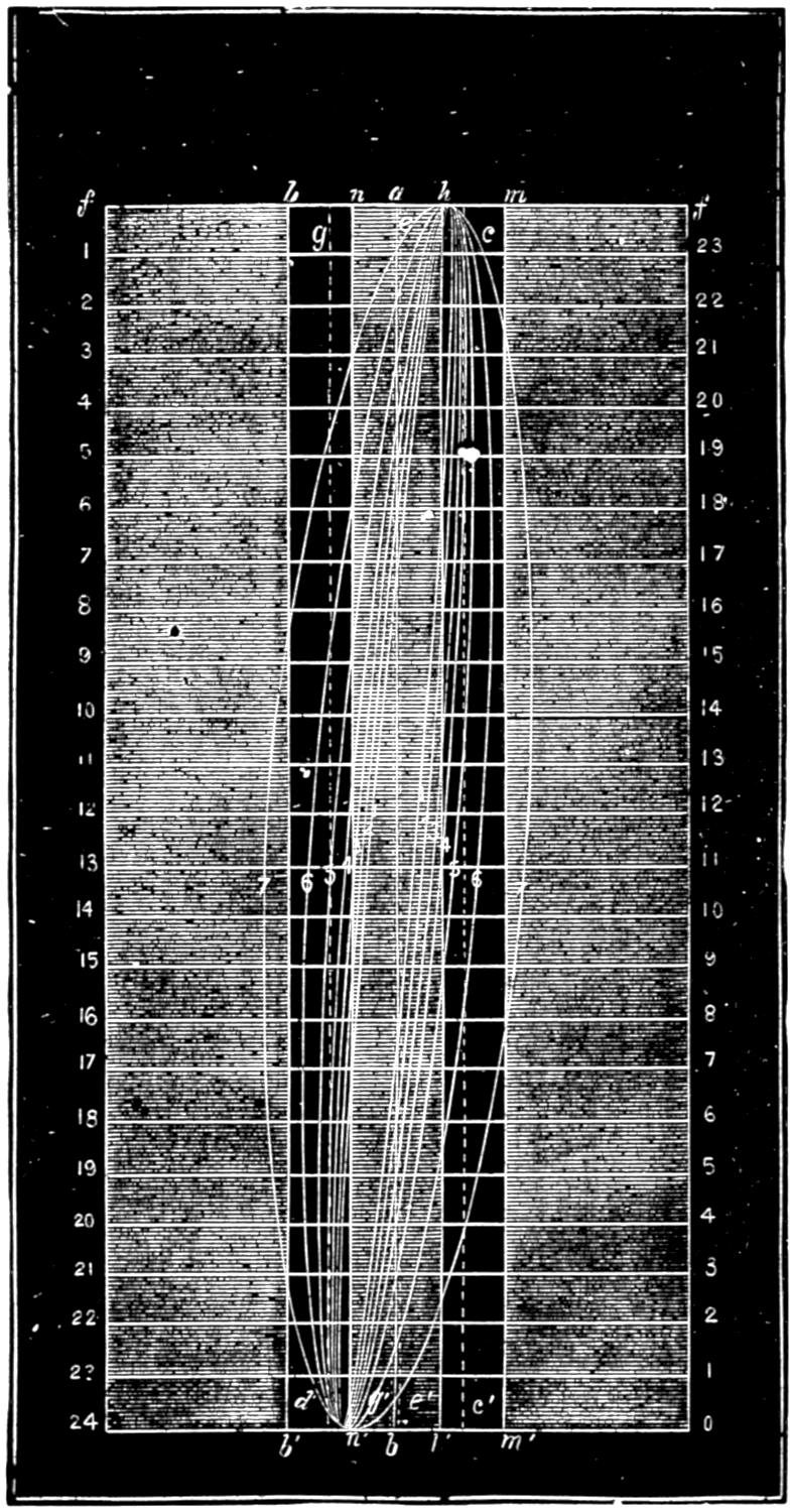
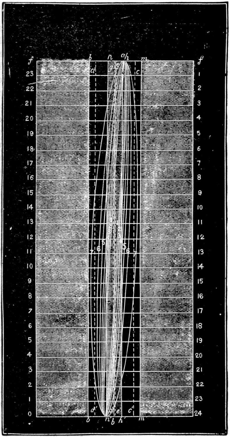
Answer. The chief difference is that the ports are not opened so wide for the same period of admission. Thus in fig. 144 is a series of motion-curves drawn with a model of a link motion like that illustrated in fig. 103. The eccentrics had 5 in. throw, and the valve ⁷⁄₈ in. lap outside and ¹⁄₁₆ in. inside. Fig. 145 represents a series of curves, drawn with the same arrangement of valve-gear, excepting that the eccentrics had 3¹⁄₂ in. throw and the valve ¹⁄₂ in. lap. In both cases the curves represent the motion of the valve when cutting off at the same point of the stroke. The following table will show the relative amount of opening of the port.
Point of Cut-Off. Width of Opening of Steam-port.
Eccentric 5 in. throw. Eccentric 3¹⁄₂ in. throw.
6 in. ⁷⁄₃₂ in. ⁵⁄₃₂ in.
8 „ ⁹⁄₃₂ „ ³⁄₁₆ „
10 „ ¹¹⁄₃₂ „ ⁷⁄₃₂ „
12 „ ⁷⁄₁₆ „ ⁹⁄₃₂ „
15 „ ⁵⁄₈ „ ³⁄₈ „
18 „ ³¹⁄₃₂ „ ¹¹⁄₁₆ „
21 „ 1 ¹⁄₄[64] „ 1 ¹⁄₃₂ „
It will be seen from this that the eccentric with 5 in. throw gives a greater width of opening for every point of cut-off than the one with 3¹⁄₂ in. throw. For the higher admissions this is not important, but when steam is cut off short it will be observed that the width of the opening is very small. At high speeds the small opening is a great disadvantage.
Question 236. Has it been determined what amount of opening is required for given speeds of the piston?
Answer. Not with any degree of accuracy. It is customary to make the area of the ports about one-tenth that of the piston. It is certain, however, that with steam-ports of this proportion an opening considerably less than their whole area is sufficient to maintain steam at boiler pressure in the cylinders. One of the defects of the link motion is that the opening of the port is very small when the steam is cut off short. It is best, therefore, to secure the largest practicable opening of the ports for the lower points of cut-off.
Question 237. What are the proportions of the valves and eccentrics used in the ordinary practice in this country?
Answer. The following report made by a committee of the Master Mechanics’ Association will show the proportions used on thirty-five different railroads, and is a fair indication of the common practice.
TABLE Outside Lap Inside Lap Travel of Valve Lead in full Gear
Showing the amount of lap, lead and travel of the valves of locomotives used on 35 of the railroads in the united states and canada.
in. in. in. in.
For locomotives running express pass. trains 25 use ⁷⁄₈ ¹⁄₈ 5 ¹⁄₁₀
„ „ „ „ „ „ 6 „ ³⁄₄ ¹⁄₁₆ 4 ³⁄₄ ¹⁄₈
„ „ „ „ „ „ 4 „ 1 ¹⁄₄ ¹⁄₄ 5 ¹⁄₈
„ „ „ accom. „ „ 20 „ ³⁄₄ ³⁄₈ 5 ¹⁄₁₀
„ „ „ „ „ „ 10 „ ⁷⁄₈ ¹⁄₁₆ 5 ¹⁄₂ ¹⁄₁₆
„ „ „ „ „ „ 5 „ ⁵⁄₈ ³⁄₁₆ 4 ¹⁄₂ ¹⁄₈
„ „ „ heavy freight „ 19 „ ³⁄₄ ¹⁄₁₆ 5 ¹⁄₁₀
„ „ „ „ „ „ 11 „ ⁵⁄₈ ¹⁄₈ 4 ¹⁄₂ ¹⁄₁₆
„ „ „ „ „ „ 5 „ ¹⁄₂ ³⁄₁₆ 4 ³⁄₄ ¹⁄₁₀
Question 238. What should be the width of the bridge between the steam and exhaust ports?
Answer. It is usually made about the same thickness as the sides of the cylinder, in order to secure a good casting; but sometimes it is necessary to make it wider, in order to prevent steam from escaping from the steam-chest into the exhaust, which is apt to be the case if a valve has little lap and a long travel.
Question 239. What determines the width of the exhaust-port?
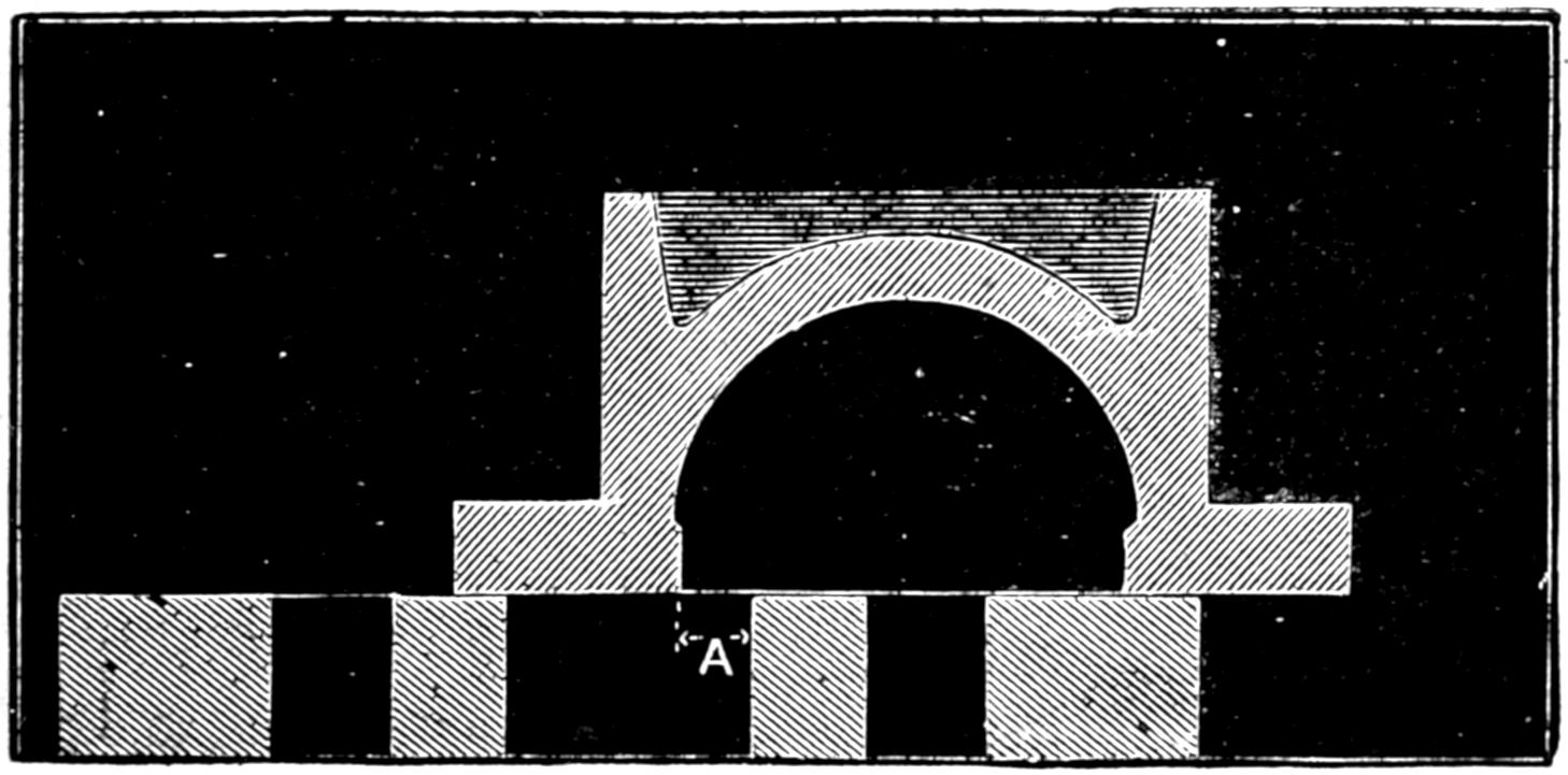
Answer. The throw of the valve. This will be clear if we refer to fig. 146, which represents a valve with a travel of 5¹⁄₂ in. It will be seen that when it is in the extreme position in which it is shown the width A of the opening of the exhaust-port is very small. If this opening is contracted too much it will of course interfere with the free escape of the exhaust steam. It is therefore best to make the exhaust-port so wide that with the greatest travel of the valve the width of its opening will be either quite or very nearly equal to the width of the steam-port.
Fig. 146.
Scale ³⁄₁₆ in. = 1 foot.
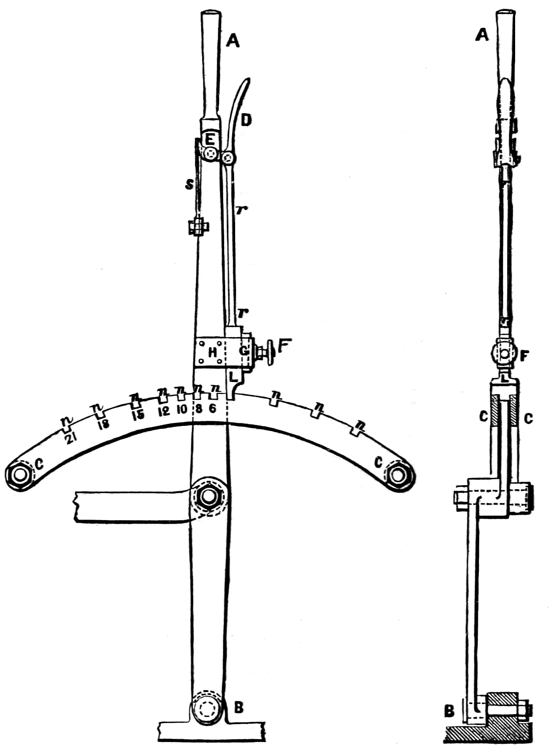
Fig. 148.
Fig. 147.
Scale ³⁄₄ in. = 1 foot.
Question 240. Where is the reverse lever located and how is it constructed?
Answer. It is located on the foot-board[65] K′ K′, as shown in plate II. It consists of a lever O, O, with the fulcrum at the lower end. The reverse-rod e k, which connects the lever with the vertical arm k of the lifting-shaft, is attached above the fulcrum of the reverse lever. Figs. 147 and 148 represent side and end views of the lever on an enlarged scale and with some of the details attached which are omitted on plate II. C, C are two curved bars, which in this country are usually called quadrants, but in England are called (and more properly) sectors. These are placed on each side of the reverse-lever and are fastened to some portion of the engine. They have notches, n, n, n, cut in them to receive the latch L, which slides in a clamp, H, and holds the reverse-lever in the notches in which it is placed. This latch is operated by a trigger, D, which is grasped by the locomotive runner when he takes hold of the handle A of the reverse-lever. The trigger works on a pin, E, as a fulcrum and is attached to the latch by a rod, r r. When the trigger is pressed up against the handle, the latch is raised out of the notches by the rod r r, and is pressed into them again by the spring s when the trigger is released. F is a set-screw which presses against a gib, G, and is intended to keep the latch tight and prevent the reverse-lever from shaking.
Question 241. How are the notches in the sector arranged?
Answer. They are usually arranged so that the steam will be cut off at some full number of inches of the stroke when the reverse-lever is in each one of the notches. They are therefore located so that the steam will be cut off at 6, 9, 12, 15, 18 and 21 inches, or at 6, 8, 10, 12, 15, 18 and 21 inches of the stroke. A notch is also placed so as to hold the link in mid-gear. In some cases as many notches as there is room for are put into the sectors. The latter seems to be much the best plan, as it gives more gradations in which the valve-gear can be worked, and it is a matter of no consequence whatever in the working of an engine whether the steam is cut off at some full or some fractional number of inches of the stroke. By referring to fig. 144 it will be seen how very great the difference of the distribution of steam must be, as indicated by the 5th, 6th and 7th motion-curves.
Question 242. How long should the reverse-lever be?
Answer. The lever should be sufficiently long so that in throwing the link from full gear forward to full gear backward the handle A will move not less than four times the distance that the link is moved. It is much better to give the end of the handle A five or even six times the motion of the link, as there will then be a much easier action in reversing the engine. This will also make it possible to use longer sectors, and give room for more notches.
Question 243. What provision is made in the reversing gear for overcoming or neutralizing the weight of the link and other parts of the valve-gear?
Answer. Their weight is counterbalanced by the pressure of a spring of some kind. In fig. 103 the two volute springs enclosed in a case, H, are used for this purpose. These are compressed by the rod m, which is attached to a short arm l, on the reverse shaft A, when the link is lowered, and consequently the tension of the spring resists the weight of the link when the latter is down or in forward gear. Different kinds of springs are used for this purpose and sometimes are attached to the reverse-lever instead of to the lifting-shaft.
Question 244. What is meant by “setting” a slide-valve?
Answer. It is to fasten the eccentrics in the right position on the axle and to adjust the length of the eccentric-rods and valve-stem so that the valves will give the required distribution of steam.
Question 245. How are the valves of a locomotive set?
Answer. After the wheels, axles, main connecting-rods and valve-gear are connected together, put the rocker-arm in its middle position, and lengthen or shorten the valve-stem so that the valve will be in the centre of the valve-face. Then place the crank on the forward centre and the full part of the forward motion eccentric above and that of the backward motion eccentric below the axle, and fasten them to the axle temporarily by tightening up the set-screws. Then throw the link down until the block comes opposite to the end of the eccentric-rod, and turn the wheels,[66] and at the same time, observe whether the travel of the valve is equal to the throw of the eccentric and also whether it travels equally on each side of the centre of the valve-face. If its travel is greater than the throw of the eccentric, raise the link up; if less, lower it down until the two are just equal, and then mark the position for the notches on the sections or quadrants to receive the latch of the reverse-lever. If the valve does not travel equally on each side of the centre of the valve-face, either lengthen or shorten the eccentric-rod, as may be necessary. Repeat this operation for the backward motion, by raising the link up until the block is opposite the end of the lower eccentric-rod. After having done this, go over the whole process again to see whether it is all correct. Now with the crank on the forward centre, and the link in full gear forward, loosen the set-screws in the forward eccentric, and move it around the axle so that the valve will have the required lead and then fasten it again. Now raise the link up into full back gear, and set the backward eccentric in the same way. Then turn the wheels so as to bring the crank on the back centre, and observe whether the lead is correct for the back end of the cylinder. If it is not, lengthen or shorten the valve-stem or eccentric-rod so as to make the lead alike at both ends, and if it is then too much or too little, it can be increased or diminished by moving the eccentrics on the axle.
Great care must be taken in setting valves to be sure that the cranks are exactly on the centres or dead points, and it is impossible to set them in that position with sufficient accuracy from the motion of the piston or cross-head, and therefore the centres of the crank-pins should always be set so as to conform to a line drawn through the centre of the cylinder and the axle. When the cylinders are horizontal, it is of course only necessary to place the cranks on a horizontal line drawn through the centre of the axle.
When the valves are set it should also be noticed whether the axle-boxes (whose construction will be explained hereafter) are in the centre of the jaws, and if not they should be moved to the centre by driving wooden wedges between them and the frames, either above or below, as may be required. The position of the boxes has a very material influence on the valve-gear.
If it is intended to lay off the notches on the sectors so as to cut off steam at certain definite points of the stroke, these points should be laid off in the guides from the motion of the cross-head. The latter being placed in any of the required positions at which steam is to be cut off, the reverse-lever should then be moved so that the link will just close the admission port. The lever can then be clamped to the sectors, and the wheels turned so as to show whether its position is correct for each end of the stroke. As before stated it is impossible to get the ordinary link-motion to cut off at exactly the same points at both ends of the cylinder, but a very close approximation can be made by proportioning the different parts properly. As has already been stated, it is believed to be a much better plan to put as many notches in the sectors as possible, than to locate them for certain definite points of the stroke.
In setting the valves of locomotives, care must be taken to turn the wheels forward for the forward motion and backward for the backward motion.
After the valves are set the position of the eccentrics on the shaft should be marked, so that in case they become loose on the road they can easily be set again. It is usual, too, to mark the position of the valves with centre-punch marks on the valve-stem and on the stuffing-box of the steam-chest, so that with a gauge made for the purpose the position of the valve can be determined without taking off the steam-chest cover.
In some cases the eccentrics are keyed on, which is done after their position is determined by setting the valves. The ends of the set-screws which are used to fasten the eccentrics should be cup-shaped and case-hardened, so as to hold as securely as possible to the axle when they are screwed down.