PART II
Reading edition
BUILDING A BLERIOT MONOPLANE
As mentioned in connection with the description of its construction, the Curtiss biplane was selected as a standard of this type of aeroplane after which the student could safely pattern for a number of reasons. It is not only remarkably simple in construction, easily built by anyone with moderate facilities and at a slight outlay, but it is likewise the easiest machine to learn to drive. The monoplane is far more difficult and expensive to build.
The Bleriot may be regarded as the most typical example in this field, in view of its great success and the very large numbers which have been turned out. In fact, the Bleriot monoplane is the product of a factory which would compare favorably with some of the large automobile plants. Its construction requires skillful workmanship both in wood and metal, and a great many special castings, forgings, and stampings are necessary. Although some concerns in this country advertise that they carry these fittings as stock parts, they are not always correct in design and, in any case, are expensive. Wherever it is possible to avoid the use of such parts by any expedient, both forms of construction are described, so that the builder may take his choice.
Bleriot monoplanes are made in a number of different models, the principal ones being the 30-horse-power "runabout," Figs. 23 and 24, the 50- and 70-horse-power passenger-carrying machines, and the 50-, 70-, and 100-horse-power racing machines. Of these the first has been chosen as best adapted to the purpose. Its construction is typical of the higher-power monoplanes of the same make, and it is more suitable for the beginner to fly as well as to build. It is employed exclusively by the Bleriot schools.
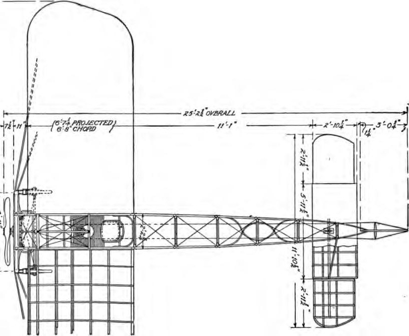
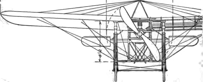
Fig. 23. Details of Bleriot Monoplane
Motor. The motor regularly employed is the 30-horse-power, three-cylinder Anzani, a two-cylinder type of which is shown in "Aeronautical Motors" Fig. 40. From the amateur's standpoint, a disadvantage of the Bleriot is the very short space allowed for the installation of the motor. For this reason, the power plant must be fan shaped, like the Anzani; star form, like the Gnome; or of the two-cylinder opposed type. It must likewise be air-cooled, as there is no space available for a radiator.
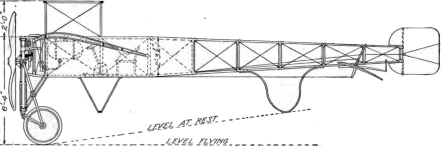
Fig. 24. Side Elevation of Bleriot Monoplane
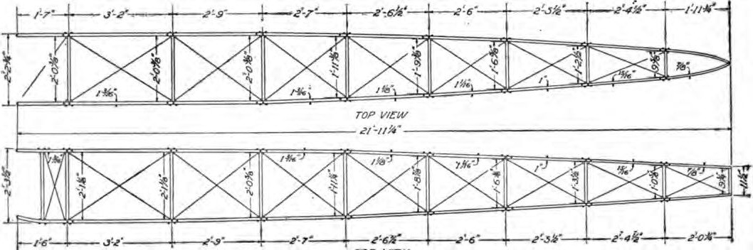
Fig. 25. Top and Side View of Bleriot Fuselage on Which Machine Is Assembled
Fuselage. Like most monoplanes, the Bleriot has a long central body, usually termed "fuselage," to which the wings, running gear, and controls are all attached. A drawing of the fuselage with all dimensions is reproduced in Fig. 25, and as the machine is, to a large extent, built up around this essential, its construction is taken up first. It consists of four long beams united by 35 crosspieces. The beams are of ash, 1 3/16 inches square for the first third of their length and tapering to 7/8 inch square at the rear ends. Owing to the difficulty of securing good pieces of wood the full length, and also to facilitate packing for shipment, the beams are made in halves, the abutting ends being joined by sleeves of 1 1/8-inch, 20-gauge steel tubing, each held on by two 1/8-inch bolts. Although the length of the fuselage is 21 feet 11 1/4 inches, the beams must be made of two 11-foot halves to allow for the curve at the rear ends.
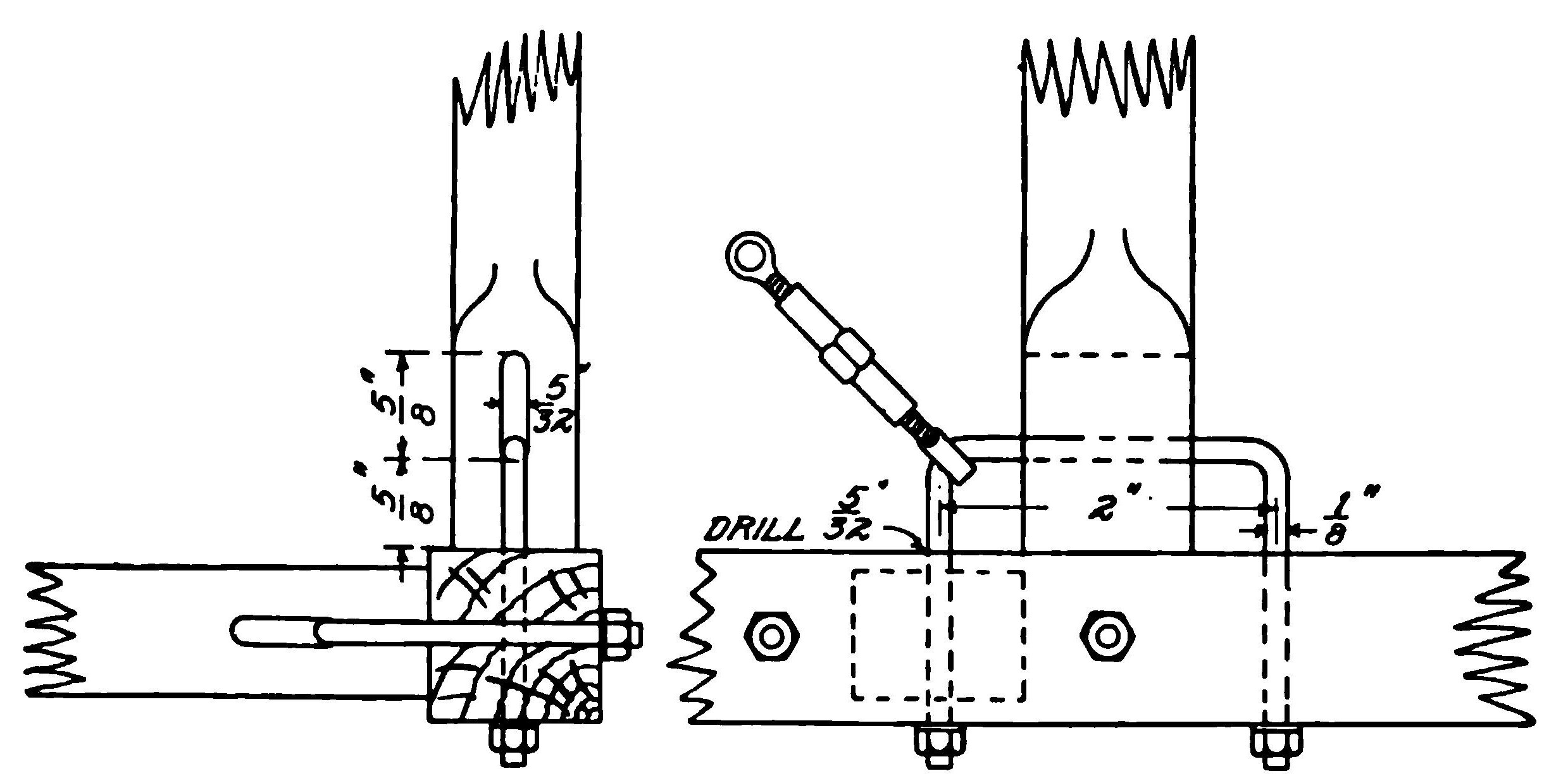
Fig. 26. Details of U-bolt Which is a Feature of Bleriot Construction
The struts are also of ash, the majority of them being 7/8 by 1 1/4 inches, and oval in section except for an inch and a half at each end. But the first, second, and third struts (counting from the forward end) on each side, the first and second on the top, and the first strut on the bottom are 1 3/16 inches square, of the same stock as the main beams. Practically all of the struts are joined to the main beams by U-bolts, as shown by the detail drawing, Fig. 26, this being one of Louis Bleriot's inventions. The small struts are held by 1/8-inch bolts and the larger ones by 3/16-inch bolts. The ends of the struts must be slotted for these bolts, this being done by drilling three holes in a row with a 5/32- or 7/32-inch drill, according to whether the slot is for the smaller or larger size bolt. The wood between the holes is cut out with a sharp knife and the slot finished with a coarse, flat file.
All of the U-bolts measure 2 inches between the ends. The vertical struts are set 1 inch forward of the corresponding horizontal struts, so that the four holes through the beam at each joint are spaced 1 inch apart, alternately horizontal and vertical. To the projecting angles of the U-bolts are attached the diagonal truss wires, which cross all the rectangles of the fuselage, except that in which the driver sits. This trussing should be of 20-gauge piano wire (music-wire gauge) or 1/10-inch cable, except in the rectangles bounded by the large struts, where it should be 25-gauge piano wire or 3/32-inch cable. Each wire, of course, should have a turnbuckle. About 100 of these will be required, either of the spoke type or the regular type, with two screw eyes—the latter preferred.
Transverse squares, formed by the two horizontal and two vertical struts at each point, are also trussed with diagonal wires. Although turnbuckles are sometimes omitted on these wires, it takes considerable skill to get accurate adjustments without them. The extreme rear strut to which the rudder is attached, is not fastened in the usual way. It should be cut with tongues at top and bottom, fitting into notches in the ends of the beams, and the whole bound with straps of 20-gauge sheet steel, bolted through the beams with 1/8-inch bolts.
Continuing forward, the struts have no peculiarity until the upper horizontal one is reached, just behind the driver's seat. As it is impossible to truss the quadrangle forward of this strut, owing to the position of the driver's body, the strut is braced with a U-shaped half-round strip of 1/2 by 1 inch of ash or hickory bolted to the beams at the sides and to the strut at the rear, with two 1/8-inch bolts at each point. The front side of the strut should be left square where this brace is in contact with it. The brace should be steam bent with the curves on a 9-inch radius, and the half-round side on the inside of the curve.
The vertical struts just forward of the driver's seat carry the inner ends of the rear wing beams. Each beam is attached with a single bolt, giving the necessary freedom to rock up and down in warping the wings. The upper 6 inches of each of these struts fits into a socket designed to reinforce it. In the genuine Bleriot, this socket is an aluminum casting. However, a socket which many would regard as even better can be made from a 7-inch length of 20-gauge 1 1/8-inch square tubing. One end of the tube is sawed one inch through the corners; two opposite sides are then bent down at right angles to form flanges, and the other two sides sawed off. A 1- by 3-inch strip of 20-gauge sheet steel, brazed across the top and flanges completes the socket. With a little care, a very creditable socket can be made in this way. Finally, with the strut in place, a 3/8-inch hole is drilled through 4 inches from the top of the socket for the bolt securing the wing beam.
The upper horizontal strut at this point should be arched about six inches to give plenty of elbow room over the steering wheel. The bending should be done in a steam press. The strut should be 1 3/16 inches square, cut sufficiently long to allow for the curve, and fitted at the ends with sockets as described above, but set at an angle by sawing the square tube down further on one side than on the other.
On the two lower beams, is laid a floor of half-inch boards, extending one foot forward and one foot back of the center line of the horizontal strut. This floor may be of spruce, if it is desired to save a little weight, or of ordinary tongue-and-grooved floor boards, fastened to the beams with wood screws or bolts. The horizontal strut under this floor may be omitted, but its presence adds but little weight and completes the trussing. Across the top of the fuselage above the first upper horizontal strut, lies a steel tube which forms the sockets for the inner end of the front wing beams. This tube is 1 3/4 inches diameter, 18 gauge, and 26 3/4 inches long. It is held fast by two steel straps, 16 gauge and 1 inch wide, clamped down by the nuts of the vertical strut U-bolts. The center of the tube is, therefore, in line with the center of the vertical struts, not the horizontal ones. The U-bolts which make this attachment are, of course, the 3/16-inch size, and one inch longer on each end than usual. To make a neat job, the tube may be seated in wood blocks, suitably shaped, but these must not raise it more than a small fraction of an inch above the top of the fuselage, as this would increase the angle of incidence of the wings.
The first vertical struts on each side are extras, without corresponding horizontal ones; they serve only to support the engine. When the Gnome motor is used, its central shaft is carried at the centers of two X-shaped, pressed-steel frames, one on the front side, flush with the end of the fuselage and one on the rear.
Truss Frame Built on Fuselage. In connection with the fuselage may be considered the overhead truss frame and the warping frame. The former consists of two inverted V's of 20-gauge, 1- by 3/8-inch oval tubing, joined at their apexes by a 20-gauge, 3/4-inch tube. Each V is formed of a single piece of the oval tubing about 5 feet long. The flattened ends of the horizontal tube are fastened by a bolt in the angles of the V's. The center of the horizontal tube should be 2 feet above the top of the fuselage. The flattened lower ends of the rear V should be riveted and brazed to strips of 18-gauge steel, which will fit over the bolts attaching the vertical fuselage struts at this point. The legs of the front V should be slightly shorter, as they rest on top of the wing socket tube. Each should be held down by a single 3/16-inch bolt, passing through the upper wall of the tube and its retaining strap; these bolts also serve the purpose of preventing the tube from sliding out from under the strap. Each side of the frame is now braced by diagonal wires (No. 20 piano wire, or 1/14-inch cable) with turnbuckles.
At the upper corners of this frame are attached the wires which truss the upper sides of the wings. The front wires are simply fastened under the head and nut of the bolt which holds the frame together at this corner. The attachment of the rear wires, however, is more complex, as these wires must run over pulleys to allow for the rocking of the rear wing beams when the wings are warped. To provide a suitable place for the pulleys, the angle of the rear V is enclosed by two plates of 20-gauge sheet steel, one on the front and one on the rear, forming a triangular box 1 inch thick fore and aft, and about 2 inches on each side, only the bottom side being open. These plates are clamped together by a 3/16-inch steel bolt, on which are mounted the pulleys. There should be sufficient clearance for pulleys 1 inch in diameter. The wires running over these pulleys must then pass through holes drilled in the tube. The holes should not be drilled until the wings are on, when the proper angle for them can be seen. The cutting and bending of the steel plates is a matter of some difficulty, and should not be done until the frame is otherwise assembled, so that paper patterns can be cut for them. They should have flanges bent around the tube, secured by the bolts which hold the frame together, to keep them from slipping off.
The oval tubing is used in the vertical parts of this frame, principally to reduce the wind resistance, being placed with the narrow side to the front. However, if this tubing be difficult to obtain, or if price is a consideration, no harm will be done by using 3/4-inch round tubing. Beneath the floor of the driver's cockpit in the fuselage is the warping frame, the support for the wires which truss the rear wing beams and also control the warping.
This frame is built up of four 3/4-inch, 20-gauge steel tubes, each about 3 feet long, forming an inverted, 4-sided pyramid. The front and back pairs of tubes are fastened to the lower fuselage beams with 3/16-inch bolts at points 15 inches front and back of the horizontal strut. At their lower ends the tubes are joined by a fixture which carries the pulleys for the warping wires and the lever by which the pulleys are turned. In the genuine Bleriot, this fixture is a special casting. However, a very neat connection can be made with a piece of 1/16-inch steel stock, 1 1/4 by 6 inches, bent into a U-shape with the legs 1 inch apart inside. The flattened ends of the tubes are riveted and brazed to the outside upper corners of the U, and a bolt to carry the pulleys passes through the lower part, high enough to give clearance for 2-inch pulleys. This frame needs no diagonal wires.
Running Gear. Passing now to the running gear, the builder will encounter the most difficult part of the entire machine, and it is impossible to avoid the use of a few special castings. The general plan of the running gear is shown in the drawing of the complete machine. Figs. 23 and 24, while some of the details are illustrated in Fig. 27, and the remainder are given in the detail sheet, Fig. 28. It will be seen that each of the two wheels is carried in a double fork, the lower fork acting simply as a radius rod, while the upper fork is attached to a slide which is free to move up and down on a 2-inch steel tube. This slide is held down by two tension springs, consisting of either rubber tubes or steel coil springs, which absorb the shocks of landing. The whole construction is such that the wheels are free to pivot sideways around the tubes, so that when landing in a quartering wind the wheels automatically adjust themselves to the direction of the machine.
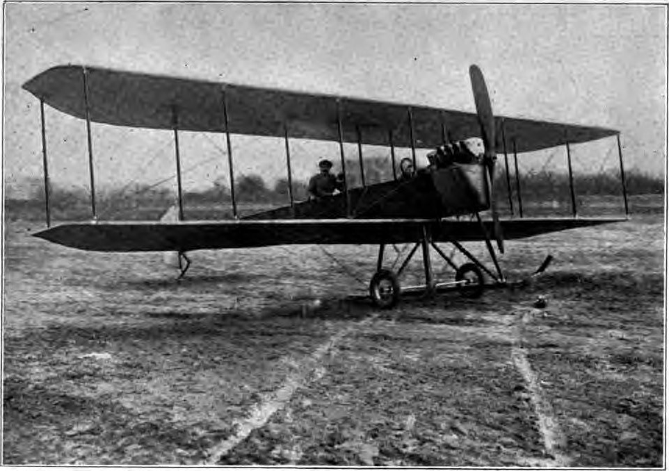
A FRENCH DEVELOPMENT OF THE WRIGHT MACHINE BUILT UNDER THE WRIGHT PATENTS There is Little Resemblance to the Original Except in Wing Form and Warping
Framework. The main framework of the running gear consists of two horizontal beams, two vertical struts, and two vertical tubes. The beams are of ash, 4 3/4 inches wide in the middle half, tapering to 3 3/4 inches at the ends, and 5 feet 2 3/4 inches long overall. The upper beam is H inch thick and the lower 1 inch. The edges of the beams are rounded off except at the points where they are drilled for bolt holes for the attachment of other parts. The two upper beams of the fuselage rest on these beams and are secured to them by two 3/16-inch bolts each.
The vertical struts are also of ash, 1 3/16 inch by 3 inches and 4 feet 2 inches long overall. They have tenons at each end which fit into corresponding square holes in the horizontal beams. The two lower fuselage beams are fastened to these struts by two 3/16-inch through bolts and steel angle plates formed from 1/16-inch sheet steel. The channel section member across the front sides of these struts is for the attachment of the motor, and will be taken up later. The general arrangement at this point depends largely on what motor is to be used, and the struts should not be rounded or drilled for bolt holes until this has been decided.
From the lower ends of these struts CC, Fig. 27, diagonal struts DD run back to the fuselage. These are of ash, 1 3/16 by 2 1/2 inches and 2 feet inches long. The rear ends of the struts DD are fastened to the fuselage beams by the projecting ends of the U-bolts of the horizontal fuselage struts, and also by angle plates of sheet steel. At the lower front ends the struts DD are fastened to the struts CC and the beam E by steel angle plates, and the beam is reinforced by other plates on its under side.
Trussing. In the genuine Bleriot, the framework is trussed by a single length of steel tape, 1 1/8 by 1/16 inch and about 11 feet long, fastened to U-bolts in the beam A, Fig. 27. This tape runs down one side, under the beam E, and up the other side, passing through the beam in two places, where suitable slots must be cut. The tape is not made in this country, but must be imported at considerable expense. Ordinary sheet steel will not do. If the tape can not be obtained, a good substitute is 1/8-inch cable, which then would be made in two pieces and fastened to eye bolts at each end.
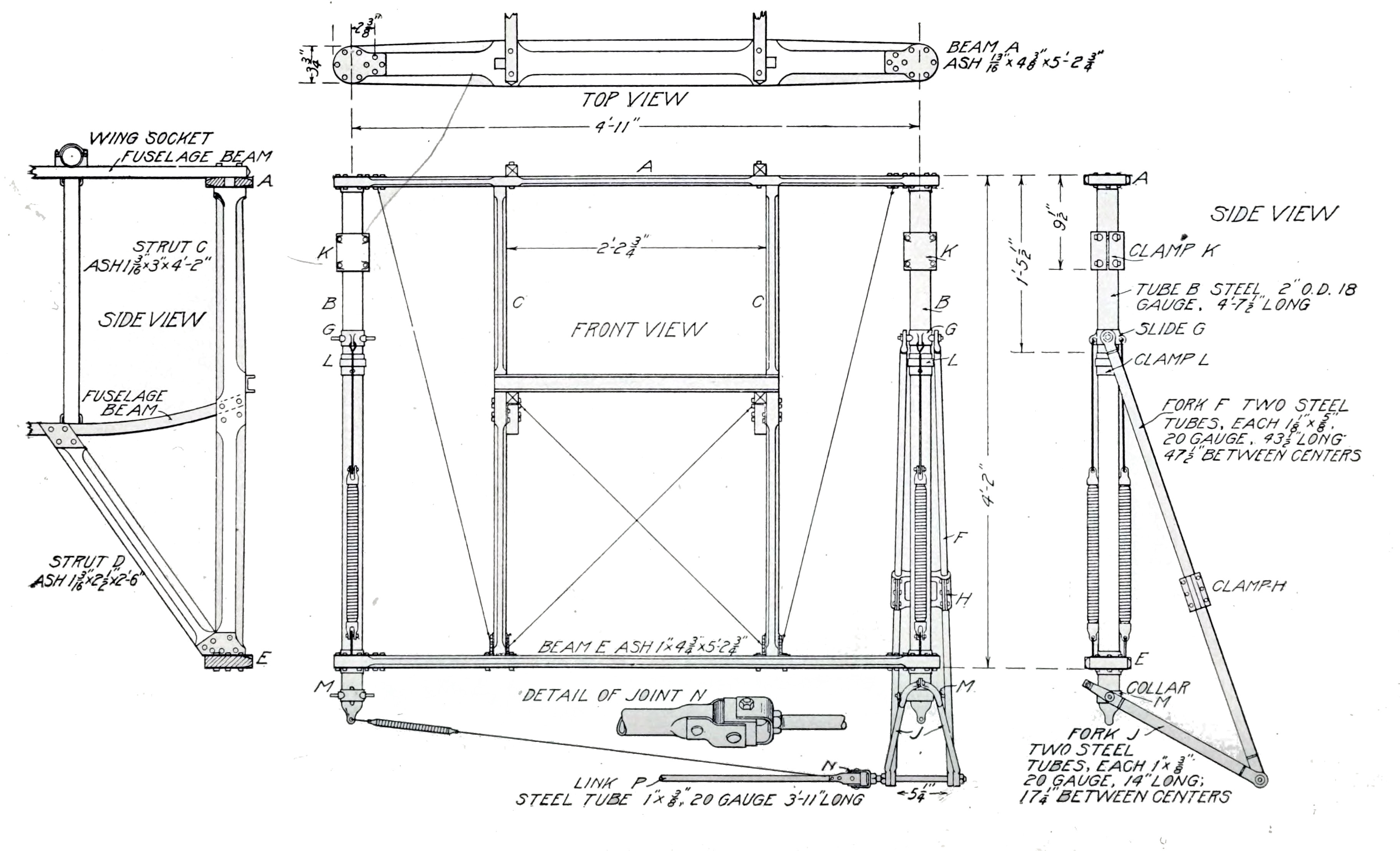
Fig. 27. Details of Bleriot Running Gear
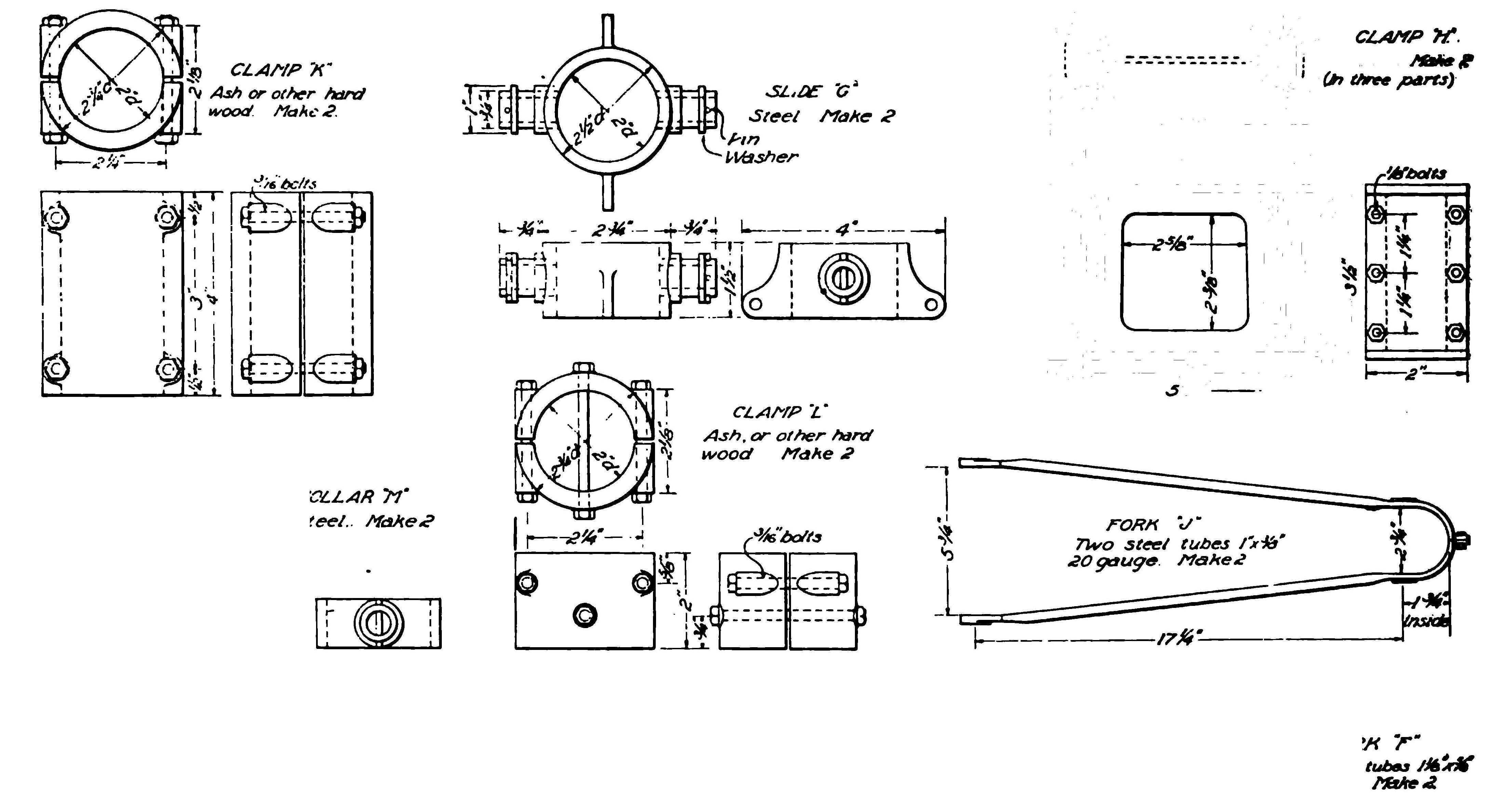
Fig. 28. Details of Various Fittings for Bleriot Monoplane
The two steel tubes are 2 inches in diameter, 18-gauge, and about 4 feet 10 inches long. At their lower ends they are flattened, but cut away so that a 2-inch ring will pass over them. To these flattened ends are attached springs and wires which run from each tube across to the hub of the opposite wheel. The purpose of these is simply to keep the wheels normally in position behind the tubes. The tubes, it will be noticed, pass through the lower beam, but are sunk only 1/8 inch into the upper beam. They are held in place by sheet-steel sockets on the lower side of the upper beam and the upper side of the lower beam. The other sides of the beams are provided with flat plates of sheet steel. The genuine Bleriot has these sockets stamped out of sheet steel, but as the amateur builder will not have the facilities for doing this, an alternative construction is given here.
In this method, the plates are cut out to pattern, the material being sheet steel 1/16 inch thick, and a 1/2-inch hole drilled through the center, a 2-inch circle then being drawn around this. Then, with a cold chisel a half dozen radial cuts are made between the hole and the circle. Finally this part of the plate is heated with a blow-torch and a 2-inch piece of pipe driven through, bending up the triangular corners. These bent up corners are then brazed to the tubes, and a strip of light sheet steel is brazed on to cover up the sharp edges. Of course, the brazing should not be done until the slides GG, Figs. 27 and 28, have been put on. When these are once in place, they have to stay on and a breakage of one of them, means the replacement of the tube as well. This is a fault of the Bleriot design that can not well be avoided. It should be noticed that the socket at the upper end, as well as its corresponding plate on the other side of the beam, has extensions which reinforce the beam where the eye bolts or U-bolts for the attachment of the steel tape pass through.
Forks. Next in order are the forks which carry the wheels. The short forks JJ, Figs. 27 and 28, which act simply as radius rods, are made of 1- by 3/8-inch oval tubing, a stock size which was specified for the overhead truss frame. It will be noticed that these are in two parts, fastened together with a bolt at the front end. The regular Bleriot construction calls for forged steel eyes to go in the ends of tubes, but these will be hard to obtain. The construction shown in the drawings is much simpler. The ends of the tubes are heated and flattened until the walls are about 1/16 inch apart inside. Then a strip of 1/16-inch sheet steel is cut the right width to fit in the flattened end of the tube, and brazed in place. The bolt holes then pass through the combined thickness of the tube and the steel strip, giving a better bearing surface, which may be further increased by brazing on a washer.
The long forks FF, which transmit the landing shocks to the springs, are naturally made of heavier material. The proper size tubing for them is 1 1/8 by 5/8 inches, this being the nearest equivalent to the 14 by 28 mm French tubing. However, this is not a stock size in this country and can only be procured by order, or it can be made by rolling out 15/16-inch round tubing. If the oval tubing can not be secured, the round can be employed instead, other parts being modified to correspond. The ends are reinforced in the same way as described for the small forks.
These forks are strengthened by aluminum clamps H, Figs. 27 and 28, which keep the tubes from spreading apart. Here, of course, is another call for special castings, but a handy workman may be able to improvise a satisfactory substitute from sheet steel. On each tube there are four fittings: At the bottom, the collar M to which the fork J is attached, and above, the slide G and the clamps K and L, which limit its movement. The collar and slide should be forged, but as this may be impossible, the drawings have been proportioned for castings. The work is simple and may be done by the amateur with little experience. The projecting studs are pieces of 3/4-inch, 14-gauge steel tubing screwed in tight and pinned, though if these parts be forged, the studs should be integral.
The clamps which limit the movement of the slides are to be whittled out of ash or some other hard wood. The upper clamp is held in place by four bolts, which are screwed up tight; but when the machine makes a hard landing the clamp will yield a little and slip up the tube, thus deadening the shock. After such a landing, the clamps should be inspected and again moved down a bit, if necessary. The lower clamps, which, of course, only keep the wheels from hanging down too far, have bolts passing clear through the tubes.
To the projecting lugs on the slides GG are attached the rubber tube springs, the lower ends connecting with eye bolts through the beam E. These rubber tubes, of which four will be needed, are being made by several companies in this country and are sold by supply houses. They should be about 14 inches long, unstretched, and 1 1/4 inches in diameter, with steel tips at the ends for attachment.
Hub Attachments. The hubs of the two wheels are connected with the link P, with universal joints N N at each end. In case the machine lands while drifting sidewise, the wheel which touches the ground first will swing around to head in the direction in which the machine is actually moving, and the link will cause the other wheel to assume a parallel position; thus the machine can run diagonally on the ground without any tendency to upset.
This link is made of the same 1- by 3/8-inch oval tubing used elsewhere in the machine. In the original Bleriot, the joints are carefully made up with steel forgings. But joints which will serve the purpose can be improvised from a 1-inch cube of hard wood and three steel straps, as shown in the sketch, Fig. 27. From each of these joints a wire runs diagonally to the bottom of the tube on the other side, with a spring which holds the wheel in its normal position. This spring should be either a rubber tube, like those described above, but smaller, or a steel coil spring. In the latter case, it should be of twenty 3/4-inch coils of No. 25 piano wire.
Wheels. The wheels are regularly 28 by 2 inches, corresponding to the 700 by 50 mm French size, with 30 spokes of 12-gauge wire. The hub should be 5 1/4 inches wide, with a 5/8-inch bolt. Of course, these sizes need not be followed exactly, but any variations will involve corresponding changes in the dimensions of the forks. The long fork goes on the hub inside of the short fork, so that the inside measurement of the end of the big fork should correspond to the width of the hub, and the inside measurement of the small fork should equal the outside measurement of the large fork.
Rear Skid. Several methods are employed for supporting the rear end of the fuselage when the machine is on the ground. The first Bleriot carried a small wheel in a fork provided with rubber springs, the same as the front wheels. The later models, however, have a double U-shaped skid, as shown in Figs. 23 and 24. This skid is made of two 8-foot strips of ash or hickory 1/2 by 3/4 inches, steamed and bent to the U-shape as shown in the drawing of the complete machine.
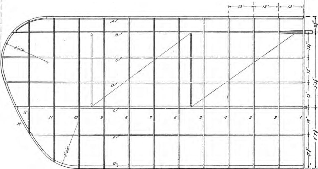
Fig. 29. Details of Framework of Bleriot Main Supporting Planes
Wings. Having completed the fuselage and running gear, the wings are next in order. These are constructed in a manner which may seem unnecessarily complicated, but which gives great strength for comparatively little weight. Each wing contains two stout ash beams which carry their share of the weight of the machine, and 12 ribs which give the proper curvature to the surfaces and at the same time reinforce the beams. These ribs in turn are tied together and reinforced by light strips running parallel to the main beams.
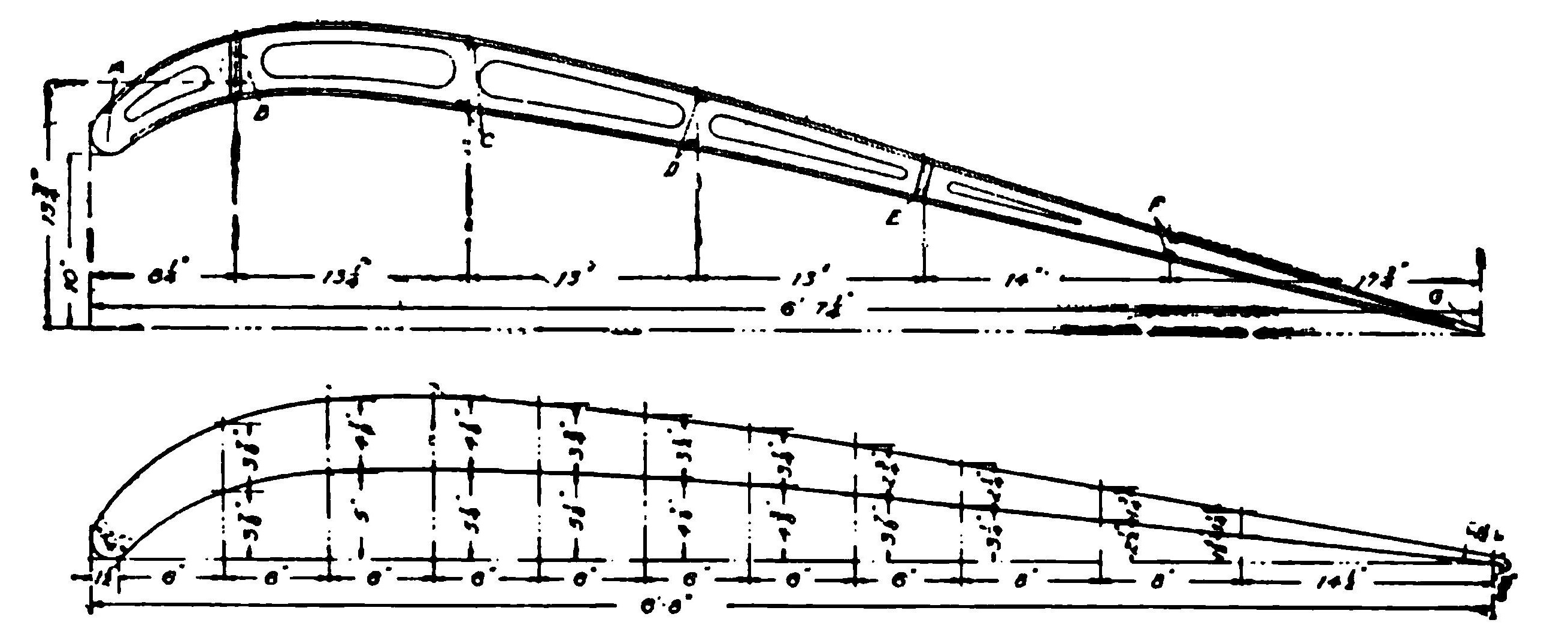
Fig. 30. Complete Rib of Bleriot Wing and Pattern from Which Web Is Cut
In the drawing of the complete wing. Fig. 29, the beams are designated by the letters B and E. A is a sheet aluminum member intended to hold the cloth covering in shape on the front edge. C, D, and F are pairs of strips (one strip on top, the other underneath) which tie the ribs together. G is a strip along the rear edge, and H is a bent strip which gives the rounded shape to the end of the wing. The ribs are designated by the numbers 1 to 12 inclusive.
Ribs. The first and most difficult operation is to make the ribs. These are built up of a spruce board 3/16 inch thick, cut to shape on a jig saw, with 3/16- by 5/8-inch spruce strip stacked and glued to the upper and lower edges. Each rib thus has an I-beam section, such as is used in structural steel work and automobile front axles. Each of the boards, or webs as they are usually called, is divided into three parts by the main beams which pass through it. Builders sometimes make the mistake of cutting out each web in three pieces, but this makes it very difficult to put the rib together accurately. Each web should be cut out of a single piece, as shown in the detail drawing. Fig. 30, and the holes for the beams should be cut in after the top and bottom strips have been glued on.
The detail drawing, Fig. 30, gives the dimensions of a typical rib. This should be drawn out full size on a strip of tough paper, and then a margin of 3/16 inch should be taken off all round except at the front end where the sheet aluminum member A goes on. This allows for the thickness of the top and bottom strips. In preparing the pattern for the jig saw, the notches for strips C, D, and F should be disregarded; neither should it be expected that the jig-saw operator will cut out the oval holes along the center of the web, which are simply to lighten it. The notches for the front ends of the top and bottom strips should also be smoothed over in the pattern.
When the pattern is ready, a saw or planing mill provided with a saw suitable for the work, should cut out the 40 ribs (allowing a sufficient number for defective pieces and breakage) for about $2. The builder then cuts the notches and makes the oval openings with an auger and keyhole saw. Of course, these holes need not be absolutely accurate, but at least 3/4 inch of wood should be left all around them.
Nine of the twelve ribs in each wing are exactly alike. No. 1, which forms the inner end of the wing, does not have any holes cut in the web, and instead of the slot for the main beam B, has a 1 3/4-inch round hole, as the stub end of the beam is rounded to fit the socket tube. (See Fig. 23.) Rib No. 11 is 5 feet 10 1/2 inches long, and No. 12 is 3 feet long. These can be whittled out by hand, and the shape for them will be obvious as soon as the main part of the wing is put together.
The next step is to glue on the top and bottom strips. The front ends should be put on first and held, during the drying, in a screw clamp, the ends setting close up into the notches provided for them. Thin 1/2-inch brads should be driven in along the top and bottom at 1- to 2-inch intervals. The rear ends of the strips should be cut off to the proper length and whittled off a little on the inside, so that there will be room between them for the strip G, 1/4 inch thick. Finally, cut the slots for the main beams, using a bit and brace and the keyhole saw, and the ribs will be ready to assemble.
Beams and Strips. The main beams are of ash, the front beam in each wing being 3 1/4 by 3/4 inches and the rear beam 2 1/2 by 5/8 inches. They are not exactly rectangular but must be planed down slightly on the top and bottom edges, so that they will fit into the irregularly-shaped slots left for them in the ribs. The front beams, as mentioned above, have round stubs which fit into the socket tube on the fuselage. These stubs may be made by bolting short pieces of ash board on each side of the end of the beam and rounding down the whole.
To give the wings their slight inclination, or dihedral angle, which will be apparent in the front view of the machine, the stubs must lie at an angle of 2 1/2 degrees with the beam itself. This angle should be laid out very carefully, as a slight inaccuracy at this point will result in a much larger error at the tips. The rear beams project about 2 inches from the inner ribs. The ends should be reinforced with bands of sheet steel to prevent splitting, and each drilled with a 3/8-inch hole for the bolt which attaches to the fuselage strut. A strip of heavy sheet steel should be bent to make an angle washer to fill up the triangular space between the beam and the strut; the bolt hole should be drilled perpendicularly to the beam, and not to the strut. The outer ends of the beams, beyond rib No. 10, taper down to 1 inch deep at the ends.
The aluminum member A, Fig. 29, which holds the front edge of the wing in shape, is made of a 4-inch strip of fairly heavy sheet aluminum, rolled into shape round a piece of half-round wood, 2 1/4 inches in diameter. As sheet aluminum usually comes in 6-foot lengths, each of these members will have to be made in two sections, joined either by soldering (if the builder has mastered this difficult process) or by a number of small copper rivets.
No especial difficulties are presented by the strips, C, D, and F, which are of spruce 3/16 by 5/8 inch, or by the rear edge strip G, of spruce 1/4 by 1 1/2 inches. Each piece H should be 1 by 1/2 inch half-round spruce, bent into shape, fitted into the aluminum piece at the front, and at the rear flattened down to 1/4 inch and reinforced by a small strip glued to the back, finally running into the strip G. The exact curve of this piece does not matter, provided it is the same on both wings.
Assembling the Wings. Assembling the wings is an operation which demands considerable care. The main beams should first be laid across two horses, set level so that there will be no strain on the framework as it is put together. Then the 12 ribs should be slipped over the beams and evenly spaced 13 inches apart to centers, care being taken to see that each rib stands square with the beams, Fig. 31. The ribs are not glued to the beams, as this would make repairs difficult, but are fastened with small nails.
Strips C, D, and F, Fig, 29, are next put in place, simply being strung through the rows of holes provided for them in the ribs, and fastened with brads. Then spacers of 3/16-inch spruce, 2 or 3 inches long, are placed between each pair of strips halfway between each rib, and fastened with glue and brads. This can be seen in the broken-off view of the wing in the front view drawing, Fig. 23. The rear edge strip fits between the ends of the top and bottom strips of the ribs, as mentioned above, fastened with brads or with strips of sheet-aluminum tacked on.
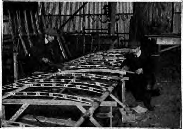
Fig. 31. Assembling the Main Planes of a Bleriot Monoplane
Each wing is trussed by eight wires, half above and half below; half attached to the front and half to the rear beam. In the genuine Bleriot steel tape is used for the lower trussing of the main beams, similar to the tape employed in the running gear, but American builders prefer to use 1/8-inch cable. The lower rear trussing should be 3/32- or 7/64-inch cable, and the upper trussing 3/32-inch.
The beams are provided with sheet-steel fixtures for the attachment of the cables, as shown in the broken-off wing view, Fig. 23. These are cut from fairly-heavy metal, and go in pairs, one on each side of the end beam, fasten with three 3/16-inch bolts. They have lugs top and bottom. They are placed between the fifth and sixth and ninth and tenth ribs on each side.
To resist the backward pressure of the air, the wings are trussed with struts of 1-inch spruce and 1/16-inch cable, as shown in Fig. 23. The struts are placed between the cable attachments, being provided with ferrules of flattened steel tubing arranged to allow the rear beam freedom to swing up and down. The diagonal cables are provided with turnbuckles and run through the open spaces in the ribs.
Control System. The steering gear and tail construction of the Bleriot are as distinctive as the swiveling wheels and the U-bolts, and the word "cloche" applied to the bell-like attachment for the control wires, has been adopted into the international vocabulary of aeroplaning. The driver has between his knees a small steering wheel mounted on a short vertical post. This wheel does not turn, but instead the post has a universal joint at the bottom which allows it to be swung backward and forward or to either side. The post is really a lever, and the wheel a handle. Encircling the lower part of the post is a hemispherical bell—the cloche—with its bottom edge on the same level as the universal joint.
Four wires are attached to the edge of the cloche. Those at the front and back are connected with the elevator, and those at the sides with the wing-warping lever. The connections are so arranged that pulling the wheel back starts the machine upward, while pushing it forward causes it to descend, and pulling to either side lowers that side and raises the other. The machine can be kept on a level keel by the use of the wheel and cloche alone; the aviator uses them just as if they were rigidly attached to the machine, and by them he could move the machine bodily into the desired position.
In practice, however, it has been found that lateral stability can be maintained more easily by the use of the vertical rudder than by warping. This is because the machine naturally tips inward on a turn, and, consequently, a tip can be corrected by a partial turn in the other direction. If, for example, the machine tips to the right, the aviator steers slightly to the left, and the machine comes back to a level keel without any noticeable change in direction. Under ordinary circumstances this plan is used altogether, and the warping is used only on turns and in bad weather.
It will be noticed that the Bleriot control system is almost identical with that of the Henri Farman biplane, the only difference being that in the Farman the cloche and wheel are replaced by a long lever. The movements, however, remain the same, and as there are probably more Bleriot and Farman machines in use than all other makes together, this control may be regarded almost as a standard. It is not as universal as the steering wheel, gear shift, and brake levers of the automobile, but still it is a step in the right direction.
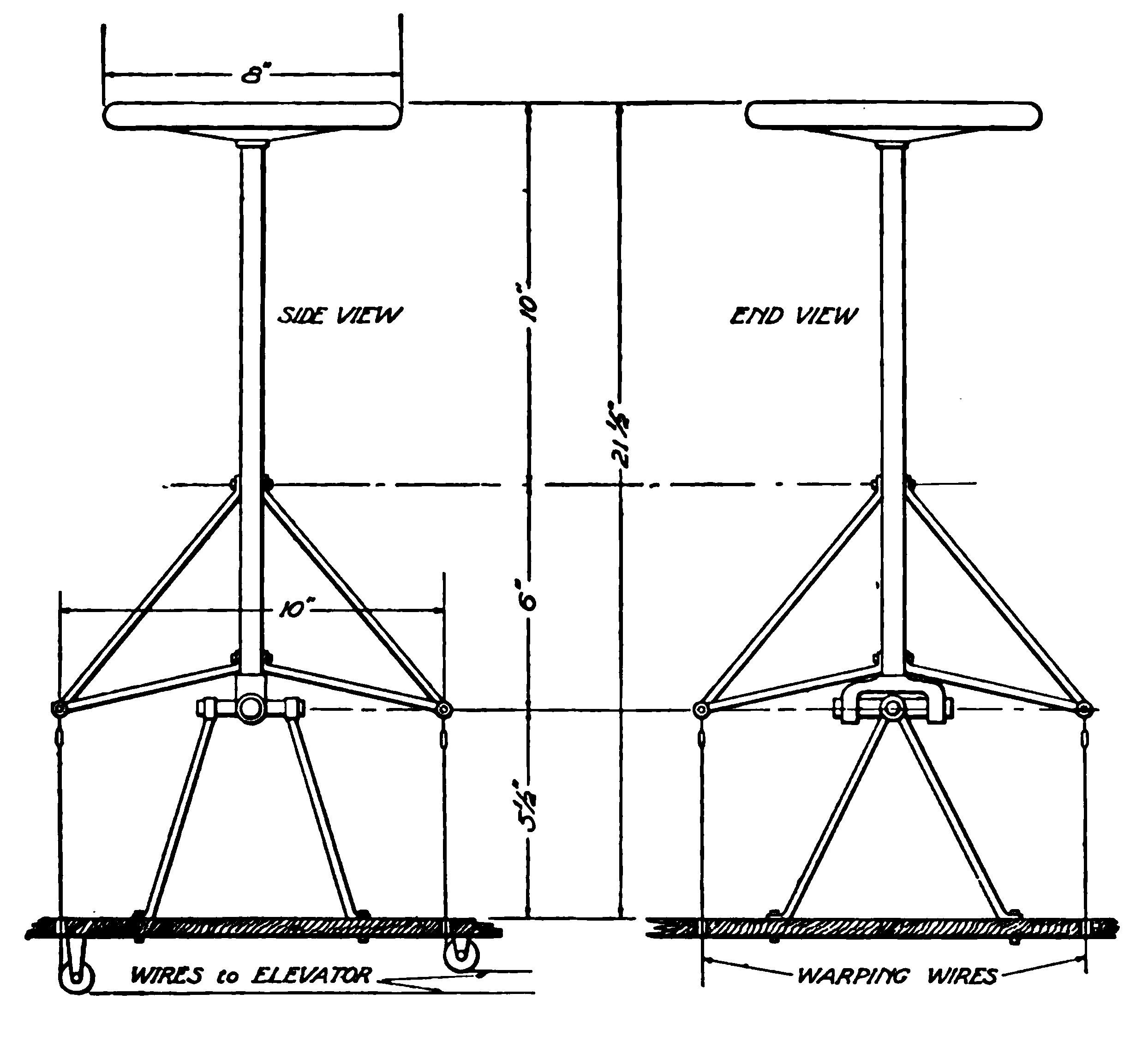
Fig. 32. Control Device of Steel Tubing instead of Bleriot "Cloche"
In the genuine Bleriot, the cloche is built up of two bells, one inside the other, both of sheet aluminum about 1/16 inch thick. The outer bell is 11 inches in diameter and 3 1/2 inches deep, and the inner one 10 inches in diameter and 2 inches deep. A ring of hard wood is clamped between their edges and the steering column, an aluminum casting passing through their centers. This construction is so complicated and requires so many special castings and parts that it is almost impossible for the amateur.
Steering Gear. While not so neat, the optional construction shown in the accompanying drawing, Fig. 32, is equally effective. In this plan, the cloche is replaced by four V-shaped pieces of 1/2-inch, 20-gauge steel tubing, attached to a steering post of 1-inch, 20-gauge tubing. At the lower end, the post has a fork, made of pieces of smaller tubing bent and brazed into place, and this fork forms part of the universal joint on which the post is mounted. The cross of the universal joint, which is somewhat similar to those employed on automobiles, can best be made of two pieces of heavy tubing, 1/2 inch by 12 gauge, each cut half away at the middle. The two pieces are then fastened together by a small bolt and brazed for greater security. The ends which are to go into the fork of the steering post must then be tapped for 3/8-inch machine screws. The two other ends of the cross are carried on V's of 1/2-inch, 20-gauge tubing, spread far enough apart at the bottom to make a firm base, and bolted to the floor of the cockpit.
The steering wheel itself is comparatively unimportant. On the genuine Bleriot it is a solid piece of wood 8 inches in diameter, with two holes cut in it for hand grips. On the post just under the wheel are usually placed the spark and throttle levers. It is rather difficult, however, to arrange the connections for these levers in such a way that they will not be affected by the movements of the post, and for this reason many amateur builders place the levers at one side on one of the fuselage beams.
From the sides of the cloche, or from the tubing triangles which may be substituted for it, two heavy wires run straight down to the ends of the warping lever. This lever, together with two pulleys, is mounted at the lower point of the warping frame already described. The lever is 12 inches long, 11 inches between the holes at its ends, and 2 inches wide in the middle; it should be cut from a piece of sheet steel about 1/16 inch thick. The pulleys should be 2 1/2 inches in diameter, one of them bolted to the lever, the other one running free. The wires from the outer ends of the rear wing beams are joined by a piece of flexible control cable, which is given a single turn over the free pulley. The inner wires, however, each have a piece of flexible cable attached to their ends, and these pieces of cable, after being given a turn round the other pulley, are made fast to the opposite ends of the warping lever. These cables should be run over the pulleys, not under, so that when the cloche is pulled to the right, the left wing will be warped downward.
It is a common mistake to assume that both pulleys are fastened to the warping lever; but when this is done the outer wire slackens off and does not move in accord with the inner wire, on account of the different angles at which they work.
Foot Levers. The foot lever for steering is cut from a piece of wood 22 inches long, hollowed out at the ends to form convenient rests for the feet. The wires connecting the lever to the rudder may either be attached to this lever direct, or, if a neater construction is desired, they may be attached to another lever under the floor of the cockpit. In the latter case, a short piece of 1-inch steel tubing serves as a vertical shaft to connect the two levers, which are fastened to the shaft by means of aluminum sockets such as may be obtained from any supply house. The lower lever is 12 inches long and 2 inches wide, cut from 1/16-inch steel similar to the warping lever.
Amateur builders often cross the rudder wires so that pressing the lever to the right will cause the machine to steer to the left. This may seem more natural at first glance, but it is not the Bleriot way. In the latter, the wires are not crossed, the idea being to facilitate the use of the vertical rudder for maintaining lateral equilibrium. With this arrangement, pressing the lever with the foot on the high side of the machine tends to bring it back to an even keel.
Tail and Elevator. The tail and elevator planes are built up with ribs and tie strips in much the same manner as the wings. However, it will hardly pay to have these ribs cut out on a jig saw unless the builder can have this work done very cheaply. It serves the purpose just as well to clamp together a number of strips of 3/16-inch spruce and plane them down by hand. The ribs when finished should be 24 1/4 inches long. The greatest depth of the curve is 1 1/4 inches, at a point one-third of the way back from the front edge, and the greatest depth of the ribs themselves 2 1/4 inches, at the same point. Sixteen ribs are required.
A steel tube 1 inch by 20 gauge, C, Fig. 33, runs through both tail and elevators, and is the means of moving the latter. Each rib at the point where the tube passes through, is provided with an aluminum socket. Those on the tail ribs act merely as bearings for the tube, but those on the elevator ribs are bolted fast, so that the elevators must turn with the tube. At its center the tube carries a lever G, of 1/16-inch steel 12 by 2 inches, fastened on by two aluminum sockets, one on each side. From the top of the lever a wire runs to the front side of the cloche, and from the bottom a second wire runs to the rear side of the cloche.
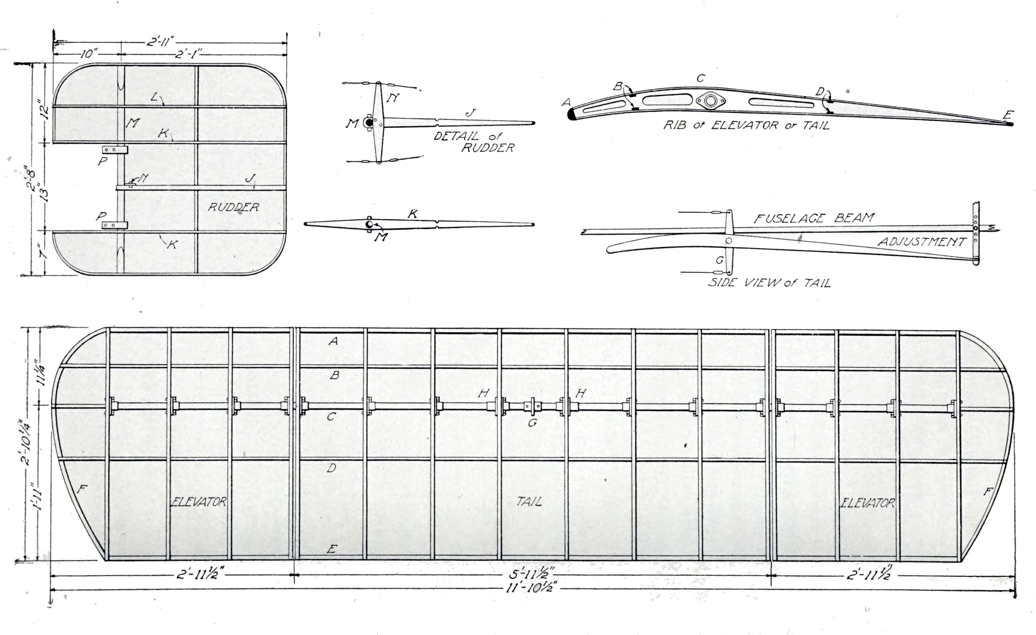
Fig. 33. Construction Details of Bleriot Tail, Elevators, and Rudder
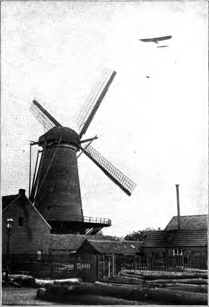
AN OLD DUTCH WINDMILL AND A MODERN FRENCH AEROPLANE This Photograph Protected By International Copyright
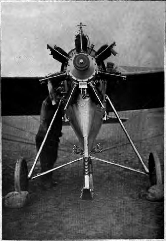
VIEW OF THE R. E. P. MOTOR AND LANDING GEAR This Machine is the Work of One of the Cleverest Aeroplane Designers in Europe
The tube is carried in two bearings HH, attached to the lower beams of the fuselage. These are simply blocks of hard wood, fastened by steel strips and bolts. The angle of incidence of the tail is adjustable, the tail itself being held in place by two vertical strips of steel rising from the rear edge and bolted to the fuselage, as shown in the drawing, Fig. 33. To prevent the tail from folding up under the air pressure to which it is subjected, it is reinforced by two 3/4-inch, 20-gauge steel tubes running down from the upper sides of the fuselage, as shown in the drawing of the complete machine, Fig. 23.
The tail and elevators have two pairs of tie strips, B and D, Fig. 33, made of 3/16- by 5/8-inch spruce. The front edge A is half round, 1- by 1/2-inch spruce, and the rear edge E is a spruce strip 1/4- by 1 1/2-inches. The end pieces are curved.
Rudder. The rudder is built up on a piece of 1-inch round spruce M, corresponding in a way to the steel tube used for the elevators. On this are mounted two long ribs KK, and a short rib J, made of spruce 3/8 inch thick and 1 3/8 inches wide at the point where M passes through them. They are fastened to M with 1/8-inch through bolts. The rudder lever N, of 1/16-inch steel, 12 by 2 inches, is laid flat on J and bolted in place; it is then trussed by wires running from each end to the rear ends of KK. From the lever other wires also run forward to the foot lever which controls the rudder.
The wires to the elevator and rudder should be of the flexible cable specially made for this purpose, and should be supported by fairleaders attached to the fuselage struts. Fairleaders of different designs may be procured from supply houses, or may be improvised. Ordinary screw eyes are often used, or pieces of copper tubing, bound to the struts with friction tape.
Covering the Planes. Covering the main planes, tail, elevators, and rudder may well be left until the machine is otherwise ready for its trial trip, as the cloth will not then be soiled by the dust and grime of the shop. The cloth may be any of the standard brands which are on the market, preferably in a rather light weight made specially for double-surfaced machines of this type; or light-weight sail cloth may be used, costing only 25 or 30 cents a yard. About 80 yards will be required, assuming a width of 36 inches.
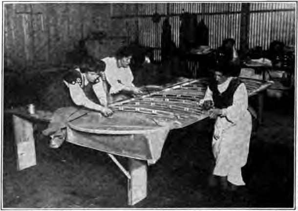
Fig. 34. Method of Mounting Fabric on Main Supporting Frame
Except on the rudder, the cloth is applied on the bias, the idea being that with this arrangement the threads act like diagonal truss wires, thus strengthening and bracing the framework. When the cloth is to be put on in this way it must first be sewed together in sheets large enough to cover the entire plane. Each wing will require a sheet about 14 feet square, and two sheets each 6 feet square will be required for the elevators and tail. The strips of cloth run diagonally across the sheets, the longest strips in the wing sheets being 20 feet long.
Application of the cloth to the wings, Fig. 34, is best begun by fastening one edge of a sheet to the rear edge of the wing, stretching the cloth as tight as can be done conveniently with one hand. The cloth is then spread forward over the upper surface of the wing and is made fast along the inner end rib. Small copper tacks are used, spaced 2 inches apart on the upper side and 1 inch on the lower side. After the cloth has been tacked to the upper sides of all the ribs, the wing is turned over and the cloth stretched over the lower side. Finally the raw edges are trimmed off and covered with light tape glued down, tape also being glued over all the rows of tacks along the ribs, making a neat finish and at the same time preventing the cloth from tearing off over the tack heads.
Installation of Motor. As stated previously, the ideal motor for a Bleriot-type machine is short along the crank shaft, as the available space in the fuselage is limited, and air-cooled for the same reason. Genuine Bleriots are always fitted with one of the special types of radial or rotary aeronautic motors, which are always air-cooled. Next in popularity to these is the two-cylinder, horizontal-opposed motor, either air- or water-cooled. However, successful machines have been built with standard automobile-type, four-cylinder, water-cooled motors, and with four-cylinder, two-cycle, aeronautic motors.
When the motor is water-cooled, there will inevitably be some difficulty in finding room for a radiator of sufficient size. One scheme is to use twin radiators, one on each side of the fuselage, inside of the main frame of the running gear. Another plan is to place the radiator underneath the fuselage, using a supplementary water tank above the cylinders to facilitate circulation. These two seem to be about the only practicable arrangements, as behind the motor the radiator would not get enough air, and above it would obstruct the view of the operator.
It is impossible to generalize to much effect about the method of supporting the motor in the fuselage, as this must differ with the motor. Automobile-type motors will be carried on two heavy ash beams, braced by lengths of steel tubing of about 1 inch diameter and 16 gauge. When the seven-cylinder rotary Gnome motor is used, the crank shaft alone is supported; it is carried at the center of two X-shaped frames of pressed steel, one in front of and the other behind the motor. The three-cylinder Anzani motors are carried on four lengths of channel steel bent to fit around the upper and lower portions of the crank case, which is of the motorcycle type.
Considerable care should be taken to prevent the exhaust from blowing back into the operator's face as this sometimes carries with it drops of burning oil, besides disagreeable smoke and fumes. The usual plan is to arrange a sloping dashboard of sheet aluminum so as to deflect the gases down under the fuselage.
The three sections of the fuselage back of the engine section are usually covered on the sides and bottom with cloth like that used on the wings. Sometimes sheet aluminum is used to cover the section between the wing beams. However, those who are just learning to operate machines and are a little doubtful about their landings often leave off the covering in order to be able to see the ground immediately beneath their front wheels.
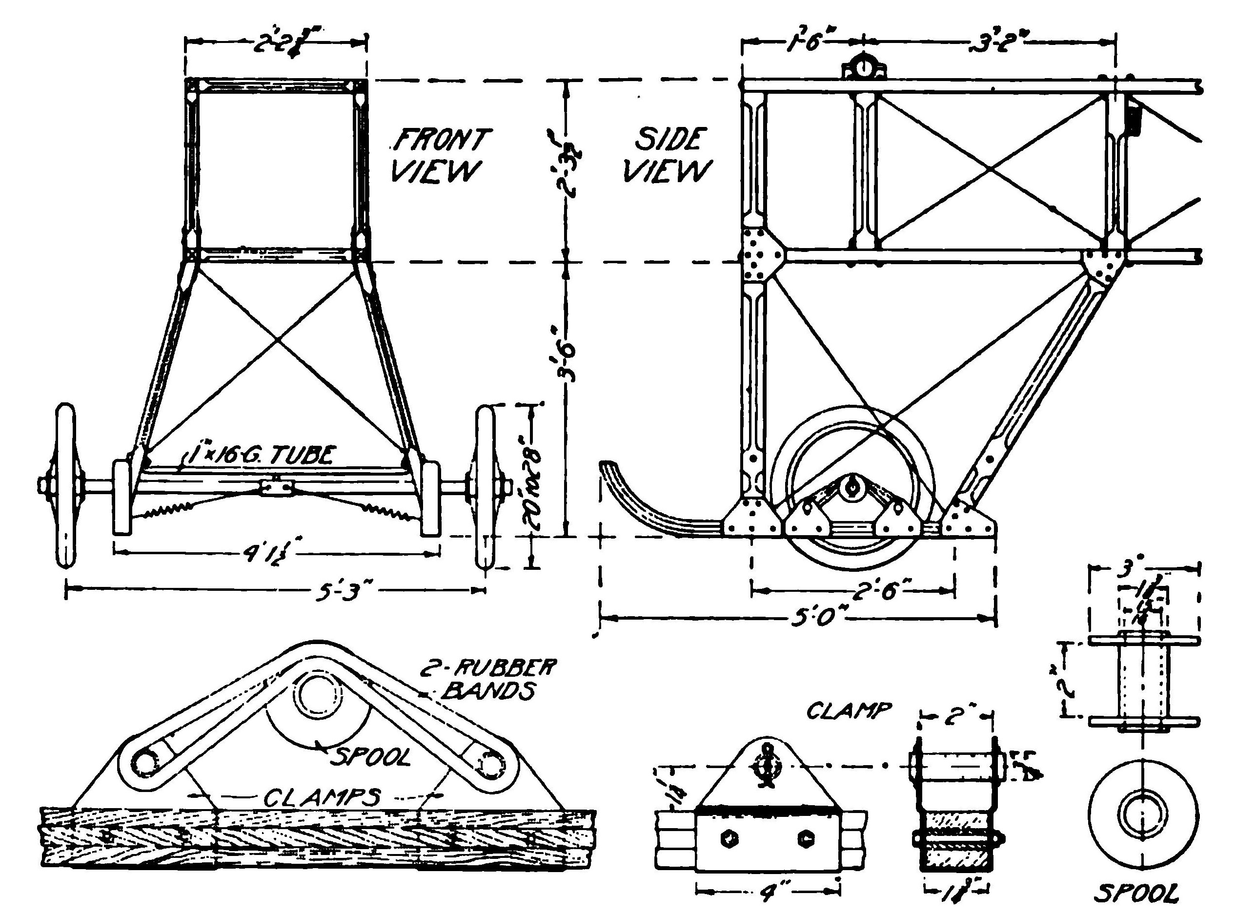
Fig. 35. Running Gear of Morane Type of Bleriot Monoplane
New Features. Morane Landing Gear. Although the regular Bleriot landing gear already described, has many advantages and ha.s been in use with only detail changes for several years, some aviators prefer the landing gear of the new Morane monoplane, which in other respects closely resembles the Bleriot. This gear, Fig. 35, is an adaptation of that long in use on the Henri Farman and Sommer biplanes, combining skids and wheels with rubber-band springs. In case a wheel or spring breaks, whether due to a defect or to a rough landing, the skids often save an upset. Besides, the tension of the springs is usually such that on a rough landing the wheels jump up and allow the skids to take the shock; this also prevents the excessive rebound of the Bleriot springs under similar conditions.
Another advantage which may have some weight with the amateur builder, is that the Morane running gear is much cheaper and easier to construct. Instead of the two heavy tubes, the four forks of oval tubing, and the many slides, collars, and blocks—most of them special forgings or castings—the Morane gear simply requires two short laminated skids, four ash struts, and some sheet steel.
The laminated skids are built up of three boards each of 5/8 by 2-inch ash, 3 1/2 feet long. These must be glued under heavy pressure in forms giving the proper curve at the front end. When they are taken from the press, three or four 1/2-inch holes should be bored at equal distances along the center line and wood pins driven in; these help in retaining the curve. The finished size of the skids should be 1 3/4 by 1 3/4 inches.
Four ash struts 1 1/4 by 2 1/2 inches support the fuselage. They are rounded off to an oval shape except at the ends, where they are attached to the skids and the fuselage beams with clamps of 1/16 inch sheet steel. The ends of the struts must be beveled off carefully to make a good fit; they spread out 15 degrees from the vertical, and the rear pair have a backward slant of 30 degrees from vertical.
Additional fuselage struts must be provided at the front end of the fuselage to take the place of the struts and beams of the Bleriot running gear. The two vertical struts at the extreme front end may be of the same 1 1/4- by 2 1/2-inch ash used in the running gear, planed down to 1 3/16 inches thick to match the thickness of the fuselage beams. The horizontal struts should be 1 3/16 by 1 3/4 inches.
The wheels run on the ends of an axle tube, and usually have plain bearings. The standard size bore of the hub is 15/16 inch, and the axle tube should be 15/16 inch diameter by 11 gauge. The tube also has loosely mounted on it two spools to carry the rubber band springs. These are made of 2 1/4-inch lengths of 1 3/8-inch tubing, with walls of sufficient thickness to make an easy sliding fit on the axle tube. To the ends of each length of tube are brazed 2 1/2-inch washers of 3/16 inch steel, completing the spool.
The ends of the rubber bands are carried on rollers of 3/4-inch, 16-gauge tubing, fastened to the skids by fittings bent up from 3/16-inch sheet steel. Each fitting is bolted to the skid with two 3/8-inch bolts.
Some arrangement must now be made to keep the axle centered under the machine, as the rubber bands will not take any sidewise strain. A clamp of heavy sheet steel should be made to fit over the axle at its center, and from this heavy wires or cables run to the bottom ends of the forward struts. These wires may be provided with stiff coil springs, if it is desired to allow a little sidewise movement.
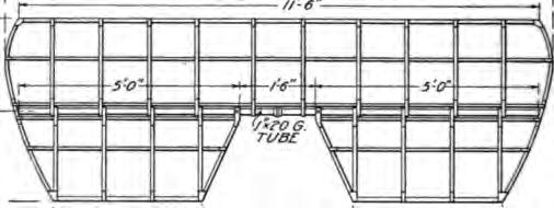
Fig. 36. Details of Bleriot Inverse Curve Tail
New Bleriot Inverse Curve Tail. Some of the latest Bleriot machines have a new tall which seems to add considerable to their speed. It consists of a fixed tail, Fig. 36, nearly as large as the old-style tail and elevators combined, with two elevator flaps hinged to its rear edge. The peculiarity of these elevators, from which the tail gets its name, is that the curve is concave above and convex below—at first glance seeming to have been attached upside down. In this construction, the 1-inch, 20-gauge tube, which formerly passed through the center of the tail, now runs along the rear edge, being held on by strips of 1/2- by 1/16-inch steel bent into U-shape and fastened with screws or bolts to the ribs. Similar strips attach the elevators to the tube, but these strips are bolted to the tube. The construction is otherwise like that previously described. It is said that fitting this tail to a Bleriot in place of the old-style tail adds 5 miles an hour to the speed, without any other changes being made.
Another slight change which distinguishes the newer Bleriots is in the overhead frame, which now consists of a single inverted V instead of two V's connected by a horizontal tube. The single V is set slightly back of the main wing beam, and is higher and, of course, of heavier tubing than in the previous construction. Its top should stand 2 feet 6 inches above the fuselage, and the tubing should be 1 inch 18 gauge. It also requires four truss wires, two running to the front end of the fuselage and two to the struts to which the rear wing beams are attached. All of the wires on the upper side of the wings converge to one point at the top of this V, the wires from the wing beams, of course, passing over pulleys.
These variations from the form already described may be of interest to those who wish to have their machines up-to-date in every detail, but they are by no means essential. Hundreds of the old-style Bleriots are flying every day and giving perfect satisfaction.
ART OF FLYING
Knowledge of the science of aeronautics and ability to fly are two totally different things. Long-continued study of the problem from its scientific side enabled the Wright Brothers to learn how to build a machine that would fly, but it did not teach them how to fly with it. That came as the result of persistent attempts at flying itself. A study of the theoretic laws of balancing does not form a good foundation for learning how to ride a bicycle—practice with the actual machine is the only road to success. The best evidence of this is to be found in the fact that several of the most successful aviators today have but a slight knowledge of the science of aeronautics. They are not particularly well versed in what makes flight possible, but they know how to fly because they have learned it in actual practice.
Reference to the early work of the Wright Brothers shows that during a period of several years they spent a large part of their time in actual experiments in the air, and it was not until these had proved entirely satisfactory that they attempted to build a power-driven machine.
Methods Used in Aviation Schools. Aviation schools are springing up all over this country and there are a number of well-established institutions of this kind abroad. In the course of instruction, the student must first learn the use of the various controls on a dummy machine. In the case of an English school, this dummy, Fig. 37, is a motorless aeroplane mounted on a universally-jointed support so as to swing about a pivot as desired. This is employed for the purpose of familiarizing the beginner with the means of maintaining equilibrium in the air.
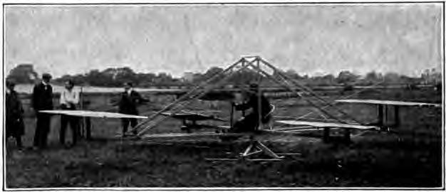
Fig. 37. Monoplane Dummy Used for Practice in Aviation School
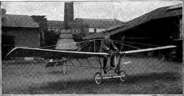
Fig. 38. Aerocycle with Treadle Power for Practice Work
A French school, on the other hand, employs a wingless machine, which is otherwise complete, as it consists of a regulation chassis with motor and propeller, all steering and elevating controls. On this, the student may practice what has come to be familiarly known as "grass-cutting," to his heart's content, without any danger of the machine taking to the air unexpectedly, as has frequently been the case where first attempts have been made on a full-fledged machine. Usually, most of such attempts result disastrously, often destroying in a moment the result of months of work in building the machine.
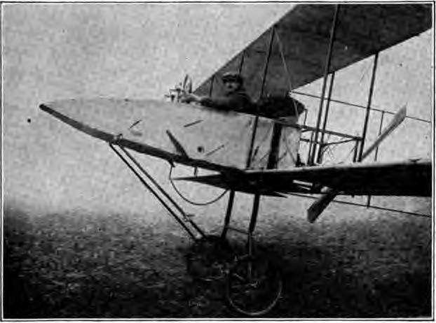
Fig. 39. Voisin Biplane with Double Control for Teaching Beginners
A French aerocycle, Fig. 38, a comparatively inexpensive machine, is also useful for practice in balancing and in short, low flights. The French apparatus in question may accordingly be considered an advance, not only over the English machine, even of the type shown in Fig. 39, which has a double control, and is especially designed for the teaching of beginners, but very much over the practice of attempting to actually fly for the first time in a strange machine, as it provides the necessary practice in the handling of the motor and the lateral steering. The machine can make high speed over the ground, but is perfectly safe for the beginner, as it is incapable of rising. Having gone through the stages represented by either of these contrivances, the best course for the learner to follow is to try gliding, taking short glides to attain the ability to quickly meet varying conditions of the atmosphere.
The fact that these glides are of extremely short duration at first need not be discouraging when it is recalled that, after several years of work, the Wright Brothers considered that great progress had been made when, in 1902, they were able to make glides of 26 seconds. During six days of the practice season of that year, they made 375 gliding flights of various distances, most of them comparatively short, but each one of value in familiarizing the glider with the conditions to be met. It is not material whether gliding or manipulation of the control levers is taken up first, as both should be mastered as far as possible before attempting to fly a regular machine.
Use of the Elevating Plane. So many things are necessary to the control of an aeroplane that thinking becomes entirely too slow a process—the aviator must be endowed with something approaching the instinct of the bird; he must be so familiar with his machine and its peculiarities that a large part of the work of controlling it is the result of subconscious movement. The control levers of many machines are so arranged that this subconscious movement on the part of the aviator directly operates the balancing mechanism. There is no time to think. When a machine rises from the ground, facing the wind as it should, its path of flight should be a gradual upward inclination, this being something difficult to accomplish at first, owing to the sensitiveness of the elevating rudder, the tendency almost invariably being to give the latter too great an angle of incidence. At this stage, the maximum velocity of flight has not yet been attained and care must be taken to keep the angle of ascent small. Otherwise, the power of the engine, which may not have reached its maximum, would not be sufficient to cause the machine to ascend an inclined path at the starting speed. If the speed of flight be reduced by the increased resistance at this point, the whole machine will slide back in the air, and if a sudden gust of wind happens to coincide with the attempt to rise at too great an angle, there is danger of it being blown over backward.
Where the machine is just leaving the ground and the elevator has been set at an excessive angle, the rear end of the skids or the tail may slap the ground hard and break off, or they will impose so much resistance upon its movement by scraping over the turf that the machine can not attain its soaring speed. It must be borne in mind, of course, that remarks such as the present can be only of the most general nature, every type of machine having its own peculiarities—in some instances, the extreme opposite of those characterizing similar machines. For example, in the Voisin 1910 type, the very large and powerful light tail tends to lift before the main planes, and if this be not counteracted, the whole machine may turn up on its end. In order to offset this tendency, the elevator must be raised so as to keep sufficient pressure beneath it; the moment of this pressure about the center of gravity must be at least equal to the pressure under the tail planes about the center of gravity of the machine, or the tail will rise unduly in the air. At least that is the theory of it—naturally, only practice with that particular machine would suffice to enable an aviator to familiarize himself with that particular peculiarity. Again, some machines are "tail heavy." But there is great difficulty in even approximating the degree of relative motion, for which reason it has been suggested, under "Accidents and Their Lessons," that a gradometer, or small spirit level, in plain sight of the aviator, should form part of the equipment of every machine. The Wrights long ago adopted the expedient of attaching a strip of ribbon to the elevator to provide an indication of motion relative to the wind.
Aeroplane in Flight. The sensation of motion after the machine leaves the ground is almost imperceptible, and it is likewise extremely difficult to tell at just what moment the aeroplane ceases running on the solid ground and takes to the air. There is a feeling of exhilaration but very little of motion. Whereas 40 miles an hour over the ground, particularly in an automobile, brings with it a lively appreciation of the speed of travel, the same speed in an aeroplane is a very gentle motion when high above the ground. If there be no objects close at hand, with which to compare the speed, the sense of motion is almost entirely lost.
Center of Gravity. The static balance of a machine should be carefully tried before commencing to fly, and particularly that of a biplane of the Wright type, in which the aviator sits behind the engine. When provision is made for carrying a passenger, his seat is placed in the center line of the machine, so that his presence or absence does not materially affect the question of lateral balance. As men are not all of the same weight, in cases in which the aviator only partly balances the engine about the center line, his weight being insufficient for the purpose, extra weights should be placed on the wing tip at the lightest end until the true balance is secured, otherwise a permanent warping, or gauchissement as the French term it, is required at this side in order to keep the machine on an even keel. In other words, the machine will carry what sailors term a port helm where the left side of the machine is lighter than the right, and vice versa, and it will be necessary to keep the rudder over to that side slightly during the entire flight to counteract this tendency.
In aeroplanes fitted with tails, the center of gravity is usually in the vicinity of the trailing edge of the main planes and, of course, should be on the center line of the machine. The center of gravity of the aviator on a monoplane should approximately coincide with that of the machine. If this be not the case, the stabilizers or the elevator must be permanently set to produce longitudinal balance. Much downward set, or the increase of the angle of incidence of the tail, will create undue resistance to flight and should be avoided when possible by bringing the weight farther forward. The center of pressure should coincide with the center of gravity, and balance will result.
Before even ground work is attempted, the position of the center of gravity should be determined in the manner shown in Fig. 40, the approximate location for four types of machines being shown. At what point the machine must be suspended, so that it can tip only frontward and backward and be evenly balanced, is a question that must be answered in order to ascertain the probability of the machine's pitching forward whenever mud, grass, or rough ground is encountered in alighting. If the center of gravity should lie in front of the axles of the ground wheels in a machine of the Farman type, trouble is sure to follow. Always consider the relation of the center of gravity to the wheels, in order that you may gain some idea of the distribution of the weight on the running gear when the machine is tipped forward 10 degrees. If the wheels are not forward far enough there will be trouble in running on the ground. The elevators must correct whatever variance there may be from the correct center of gravity and position of the wheels, and the manipulation of the elevators for that purpose requires skill. If the tail be very heavy, the elevator may not be able to counteract that defect.
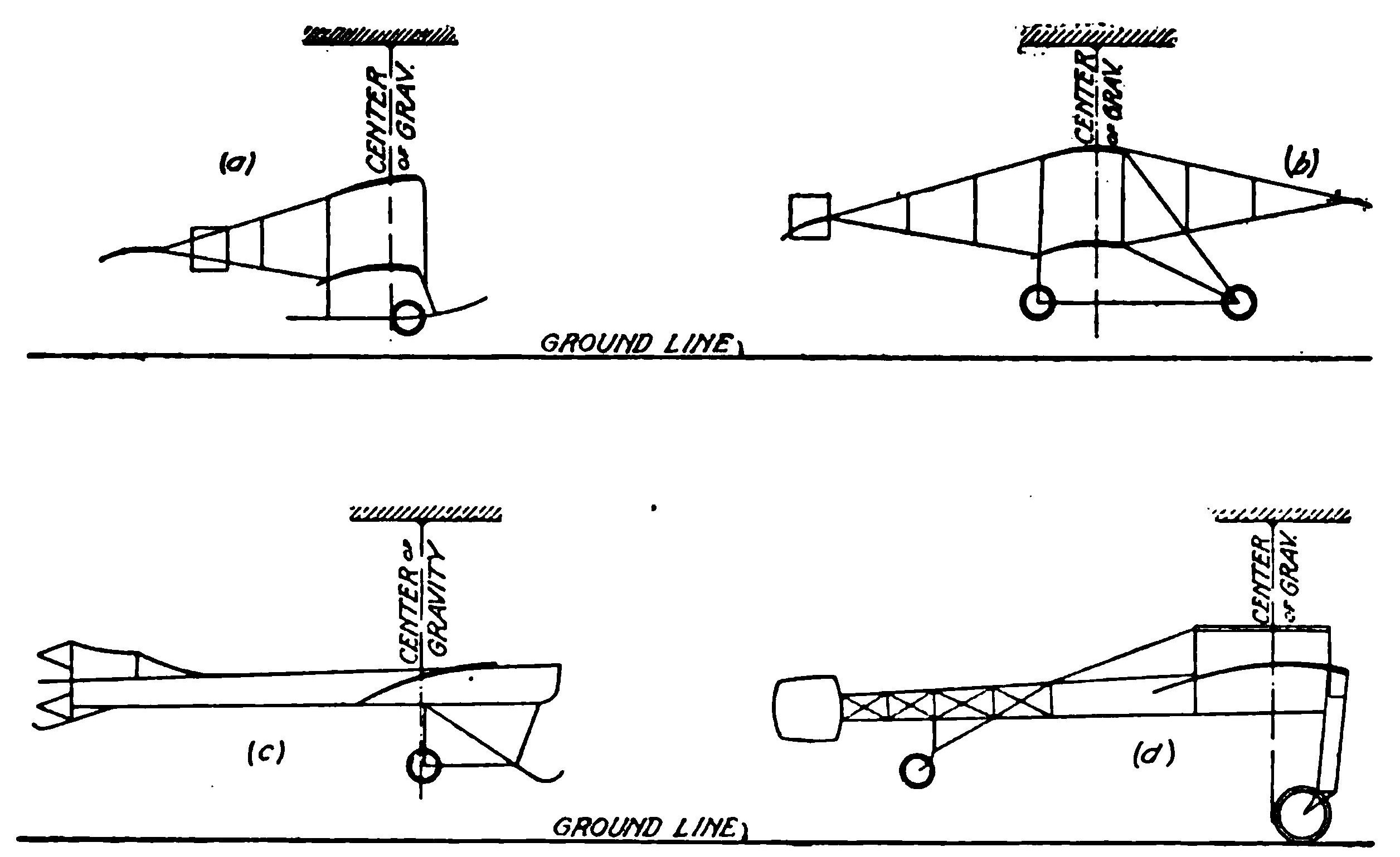
Fig. 40. Method of Determining Center of Gravity of Different Types of Machines
The position of the center of gravity of a machine in regard to lateral stability in flight is a matter of far greater importance than untried aviators realize. Having it too low is quite as bad as too high, as in either case there is a tendency to upset. Although the dihedral angle is considered wasteful of power, it seems to do more to secure inherent stability than any other device. Devices for maintaining stability automatically are to be frowned upon in the present state of the art. The sensitive perception and quick response which come with intimate knowledge of a machine's peculiarities, are at present worth more than gyroscopes and pendulums. To acquire this intimate knowledge, the aviator must familiarize himself thoroughly with the machine; he must become so accustomed to controls that he and the machine are literally one. A practiced bicycle rider does not have to think about balance, neither does the practiced aviator, yet he must always be prepared to meet motor stoppages, unusual air disturbances, and breakages. A leap from the ground directly into the air, without preliminary practice, means certain accident, to put it mildly.
Center of Pressure. But although the center of gravity remains approximately constant, the center of pressure is continually varying and is never constant for many seconds. The center of pressure on an aerocurve constructed to Phillips' design, Fig. 41, is about one-third of the chord from the leading edge of the plane under normal conditions, i.e., when the angle of incidence is about 8 degrees between the direction of motion of the plane and that of the air. At the moment this angle is increased the center of pressure moves toward the rear, and vice versa. The center of gravity must be moved to coincide with this new position, or the center of pressure must be artificially restored by the use of supplementary planes or elevators, moving in a contrary direction. A forward movement of the center of pressure tends to lower the tail of the machine, when the intensity of the pressure is unchanged, and to counterbalance this the rear elevator must have its angle of incidence increased in order to increase the lift at the rear of the machine, or it will slide down backward. The alternative to be adopted in case of temporary lack of engine power is to decrease the angle of the elevator and allow the aeroplane to sweep downward, thus gaining momentum. The increase of speed will then be sufficient probably to enable the machine to continue in a horizontal flight, when the center of pressure is again restored to its normal position.
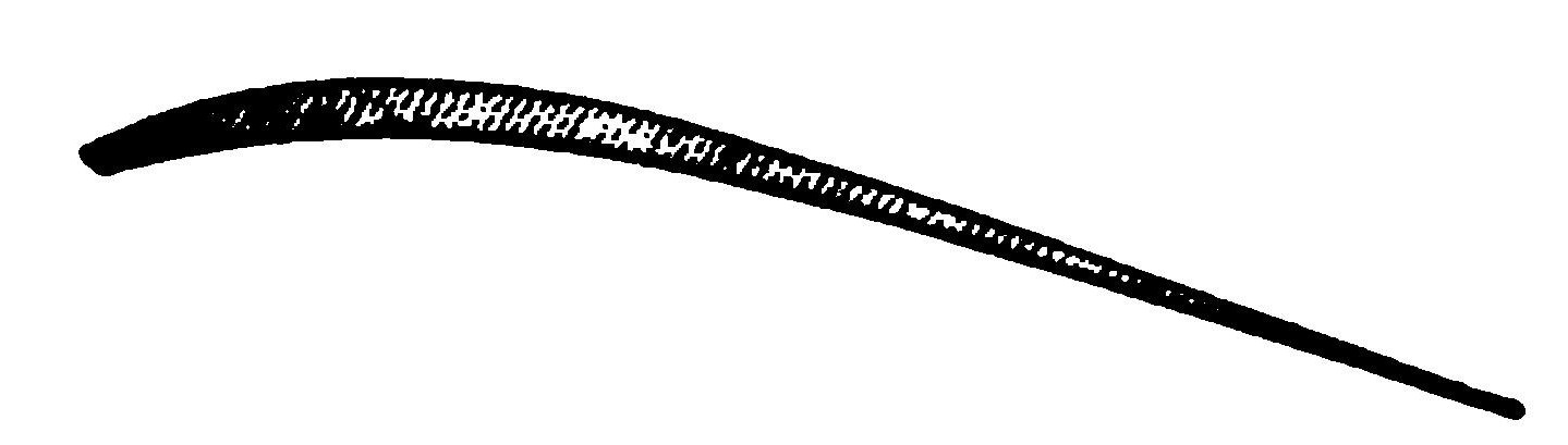
Fig. 41. Aerocurve of Phillip's Design
Ground Practice. First of all, the aviator should familiarize himself with his seat for it is from that place that he must judge wind effects, vibration, motor trouble, and the thousand and one little creaks and hums that will ultimately mean so much to him. Not until he has thoroughly accustomed himself to his seat, should he try to run along the ground. This done, hours should be spent running up and down and around the field to learn the use of the rudder, particularly on rough ground. The runs should be straight so that when the time comes to leap into the air, the aviator may be sure that he is on an even keel, and flying straightaway. In order to prevent the possibility of leaving the ground unexpectedly in practice, trials should be made only in calm weather and with the motor well throttled down so that the machine will be reduced to a speed of not more than 15 miles per hour. After a time this may be increased to 20, but the latter is the maximum for ground practice, as the machine will rise at speeds slightly exceeding this. In these practice rims on the ground, the student should learn to gauge the rush of air against his face, as when aloft his best gauge will be the wind pressure on his cheeks, as that will tell him whether he is moving with sufficient speed to keep up or not. It will also tell him ultimately whether he is moving along the ground fast enough to leap up.
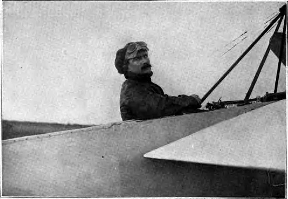
VEDRINES, ONE OF THE MOST FAMOUS AND SUCCESSFUL OF EUROPEAN AEROPLANE PILOTS, SEATED IN A DEPERDUSSIN MONOPLANE
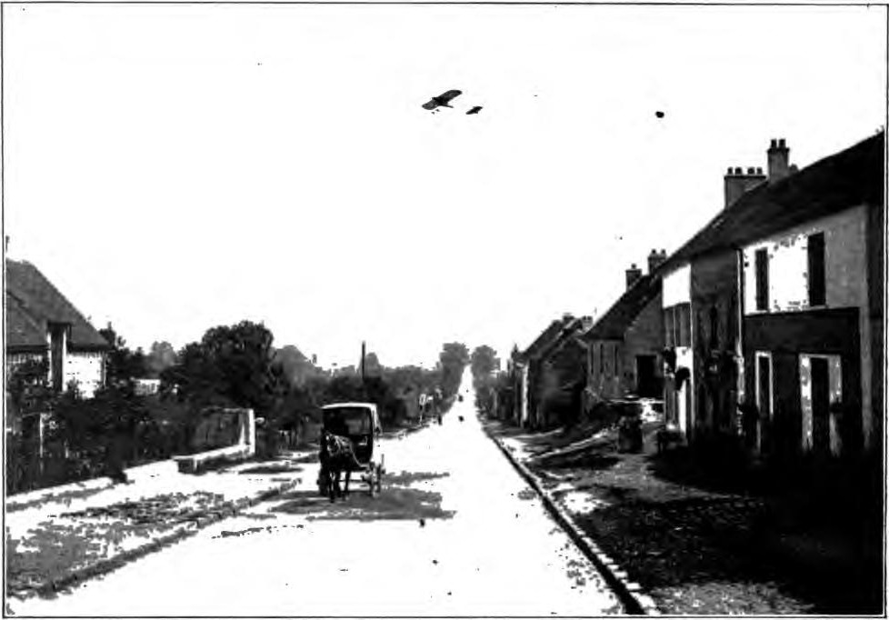
AIRSHIP CROSSING ONE OF THE NATIONAL ROADS IN RURAL FRANCE This Photograph Protected by International Copyright
In this stage of experimenting on the ground, the elevator is kept neutral as far as possible. With increasing skill its use may be ventured, but only sparingly, for it takes very little to lift the machine from the ground with a speed in excess of 20 miles per hour. It will soon be discovered that the elevator can be used as a brake to prevent pitching forward. The tail elevators on the Farman or Bleriot running gear are very effective owing to the blast of the propeller, even when the main planes are not moving forward at lifting speed. With the Curtiss type of running gear and a front elevator only, it is often possible at 18 to 20 miles per hour to raise the front wheel off the ground for a second or two—facts which indicate that at 25 to 28 miles per hour, the elevator is far more effective.
First Flight. The first actual flight should be confined to a short trip parallel to the ground and not more than one or two feet above it. At first, the student should see how close he can fly to the ground without actually touching it, which he can do by gradually increasing his forward speed. This must be done in an absolute calm as an appreciable amount of wind will bring in too many other factors for the student to master at so early a stage. This practice should be continued in calm air until short, straight flights can be made a foot or two from the ground with the motor wide open. If it be found that the machine barely flies straightaway with the full power of the motor, the latter is either badly out of adjustment, or a more powerful engine is required. In an under-powered machine turning would be suicidal. Moreover, the resistance encountered in the air is greater than on the ground and may be such that the speed is not sufficient for sustentation. Fig. 42, (a) and (b), show why it is possible to run along the ground faster than it is possible to travel in the air, under certain conditions, and why the ground can be left at low speed. If it were possible to drive a machine with such enormous projected areas as BB, shown in Fig. 42 (b), a man could fly slowly for an indefinite period. But the projected area is greater than the air displaced by the propeller, and it is impossible to fly except with a moderate angle of incidence, giving projected areas A A, Fig. 42 (a). The student, as he increases in skill, may venture to a height of 10 feet, which should be maintained as accurately as before, and after making a run of 100 yards, the machine should be pointed down, but ever so slightly. The wind pressure on the face immediately becomes greater. Within a foot or two of the ground the motor should be cut off or throttled. This should be tried ten or fifteen times, and the height increased to 30 or 40 feet, in order that the student may familiarize himself with the sensation of coasting. At the end of each glide the machine will seem to become more responsive, as indeed it does, for gliding down greatly increases the efficiency of the elevator and other controls, because of the increased speed. Gliding down steep angles is often the aviator's salvation in a tight place, particularly when the motor fails, a side gust threatens or an air pocket is encountered.
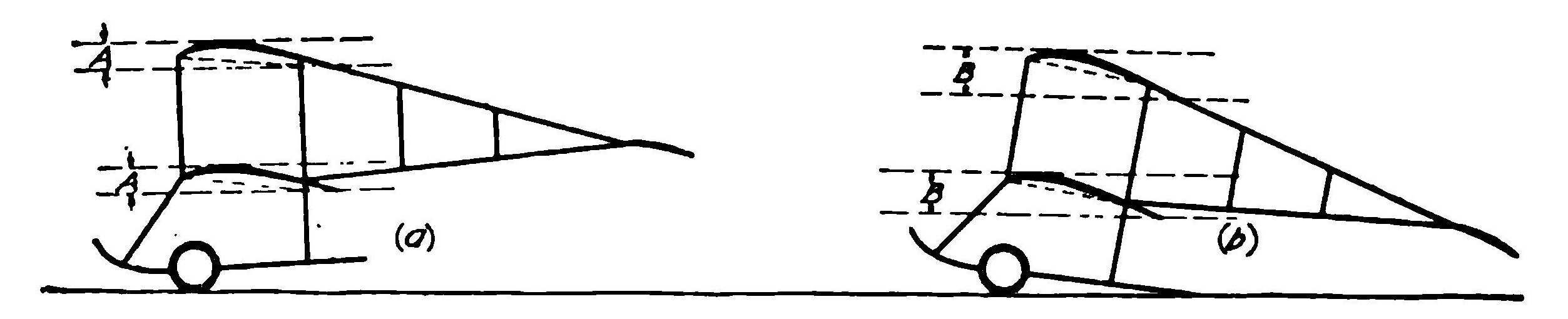
Fig. 42. Diagrams Showing Greater Projected Area of Main Plane when Running along Ground
Warping the Wings. When sufficient confidence has been attained at a height of 30 to 40 feet, the ailerons or warping devices may be tried judiciously. Here the intention should be to correct any tendency to side tipping, and not purposely to incline the machine as far as possible without actually causing a wreck. The use of the lateral control may cause the machine to swerve a little, but that may be ignored. Before landing, a straight course should be taken so that the machine will always come down on an even keel. With increasing practice, the student may fly higher, but always with the understanding that there is a limit to the angle of incidence. An automobile is retarded when it strikes a short, steep hill; so is an aeroplane. No aeroplane has yet been built that can take a steep angle and climb right up that grade continuously. Altitude is reached by a series of small steps and at comparatively low angles, as unless the course is straightened out at regular intervals, a machine will lose its speed and tend to plunge tail first, just as is the case when an attempt is made to rise from the ground at too sharp an angle.
In warping the wings an increase of lift imparted to one wing of the machine is produced by increasing the angle of incidence of the whole or part of the wing, or by an increase of pressure under that wing, and will tend to cause that side of the machine to rise and the other side to lower, the result being that the machine will be liable to slide through the air diagonally. In the majority of aeroplanes there are no fins or keels to counteract this movement, and lateral stability must be restored by artificially increasing the lift of the depressed wing. This can be done by warping, or lowering the trailing edge of the depressed wing and increasing its lift, and simultaneously raising the trailing edge of the other wing, thus decreasing the angle of incidence of the latter and reducing its lifting effect. This applies to flight on a straight course, whatever the cause may be that tends to upset lateral stability. It will be seen, therefore, that the center of gravity remains constant and the center of pressure must be manipulated to restore stability. This manipulation is much more rapid and positive than the alteration of the center of gravity by the movement of the aviator's body resorted to in the early gliding flights of pioneer experimenters.
Making a Turn. The first turn should be made over a large field and the diameter of the turn should be at least half a mile. The height should be not less than 50 feet. After that level has been maintained, the rudder should be moved very gingerly. The machine will lean in almost immediately, because the outer end travels at a higher speed than the inner and therefore has a greater lift. Warping or working the ailerons should be resorted to as a means of counteracting this tendency, and the rudder swung to the opposite direction, if necessary. It is obvious that if the rudder will cause the machine to bank when swung in one direction, it will right the machine again when swung in the opposite direction. It is even possible to turn the machine on an even keel by anticipating the banking, simply by correctly using the rudder, which was necessary in the old Voisin machine flown by Farman in 1908, because it had no mechanical lateral control. The student should learn the correct angle of banking, i.e. the angle at which the machine will neither skid nor slide down and which is most economical of power because it requires less use of the lateral controls. The necessity of "feeling the air" is greater in turning than in any other phase of flying. By "feeling the air" is meant the ability to meet any contingency intuitively and not until this is acquired can the student become an expert aviator. When it has been acquired, safe flying is assured and is dependent only upon the integrity of the planes, motor, and controls. By using the rudder discreetly and by banking simply far enough to partially offset the centrifugal force of turning, the use of the lateral control will not be necessary in still air. Even too short a turn can be corrected by a quick use of the rudder.
The peculiarities existing between different types of monoplanes become even more marked than between the biplane and the monoplane. For example, in piloting a Bleriot monoplane, Fig. 43, it is necessary to take into account the effect of the engine torque. As the engine rotates in a right-hand direction, from the point of view of the pilot, the left wing tends to rise in the air, owing to the depression of the right side of the machine. The machine also tends to turn to the right, and this must be counteracted by putting the rudder over to the left. An aeroplane answers its controls with comparative slowness, with the exception, perhaps, of the Wright machine, which is noted for its sensitive and quick response to every movement of the levers. All control movements must, therefore, be very gentle, as the behavior of an aeroplane is more like that of a boat than that of an automobile. The action of the elevator has already been described, and it is, perhaps, the most difficult of all the controls to manipulate, in that it requires the exercise of a new sense. The direction rudder is naturally a more familiar type of control, and in action is similar to the rudder of a boat.
The torque of the motor renders it advisable for a novice to turn his machine to the right, if a right-hand propeller be used, and vice versa. If two propellers, turning in opposite directions, are employed, as in the Wright biplane, there is no inequality from the torque of the motor. Since torque is not noticeable in straight flying, straightening out again will always serve the student when he finds himself in trouble on a turn. When the use of the rudders and ailerons has reduced the speed, a downward glide will increase it again, and if the motor should stop on a turn, such a downward glide is immediately imperative. When the machine is thus gliding, a change in the fore-and-aft balance becomes at once apparent, because the blast of the propeller no longer acts on the tail, and the elevator must then be used with greater amplitude to obtain the same effect.
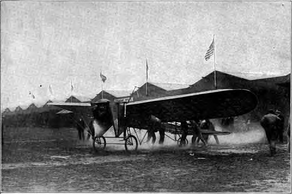
Fig. 43. Making a Start with Bleriot Monoplane
Only by constant practice in calm air can the student familiarize himself with exactly the amount of warping and rudder control to employ to property offset the lowering of the inner wing in rounding a turn. If this be not corrected, the whole machine tends to bank excessively and will be apt to slide downward in a diagonal direction, Fig. 44. This is a perilous position for the aviator and must be guarded against by the manipulation of the warping control so as to increase the lift of the inner wing of a biplane, at the same time, employing the rudder to counteract this tendency. The use of the rudder is of even greater importance on the monoplane, as, in this case, warping the inner wing tends to direct the whole machine downward instead of raising the inner wing itself. Several bad accidents have resulted from monoplanes refusing to respond to the warping of the inner wing when making a turn. In such machines, the rudder must be practically always employed in connection with the warping of the wings in order to keep the machine on an even keel, although the controls may not actually be interconnected, this being one of the grounds on which foreign manufacturers are trying to make use of the Wright principle, without infringing the Wright patents, as while they employ warping in connection with the simultaneous use of the rudder, the controls are not attached to the same lever as in the Wright machine.
Fig. 44. An Aeroplane "Banking" as it Rounds a Pylon
Lateral resistance must also be taken into consideration in turning, otherwise the machine, if kept on an even keel, will tend to skid through the air and turn about its center of gravity as a pivot. In the case of an automobile, the resistance to lateral displacement is great, though on a greasy surface it may be small, as when the machine skids sideways, a suitable banking of the road being necessary to prevent this on turns. Many hold that the banking of the aeroplane on turns is only the direct effect of the turning itself, but the fallacy of this will be apparent upon a consideration of the law of centrifugal force. It is obvious that to make a turn, some force must be imparted to the machine to counteract the effect of the centrifugal force upon the machine as a whole. And as the sidewise projection of the machine is small, a compensating force must be introduced. This can be done only by previously banking up the machine on the outer wing, so that the pressure of the air under the main plane can counteract the tendency to lateral displacement. The force then acting under the planes is in a diagonal direction, and the angle at which it is inclined vertically depends upon the banking of the planes, it being normal to their greater dimension. This force can be resolved into two forces, one perpendicular and one horizontal, the magnitude of each being dependent upon the degree of banking. When the speed of the machine is higher, the amount of banking must be greater in order to increase the value of the horizontal component in proportion to the increase of the value of the centrifugal force at the higher speed, in spite of the fact that the forces acting under the planes are also greater due to the higher speed.
As the curve commences, the rudder being put over, the difference of the pressures on the two wings, owing to their different flying speeds comes into account, as already explained, and care must be taken that the banking does not increase abnormally. When the turn is completed, the rudder is straightened and the machine is again brought to an even keel with the aid of the wing-warping control, or the ailerons. The effect of a reverse warping to prevent excessive banking, lowering the inside wing tip incidentally, puts a slight drag on that wing and assists in the action of turning, as does also the provision of small vertical planes between the elevator planes of the original Wright machine. Since the adoption of the headless type, these surfaces are placed between the forward ends of the skids and the braces leading down to them.
In making a turn, say, to the left, the outside or right-hand wing is first raised by lowering the wing tip on that side and the rudder is then put over to the left. When the correct amount of banking is acquired, the wing tip is restored to its normal position, and probably the left wing tip may have to be lowered slightly to increase the lift on that side owing to its reduced speed. When the turn is completed, the rudder is straightened out and the left wing tip lowered to restore the machine to an even keel. Both Glenn Curtiss in this country and R. E. Pelterie in France have shown that it is possible to maneuver without using the rudder at all, the ailerons or wing tips alone being relied upon for this purpose.
Before flights in other than calm air are attempted, much practice is required. The machine must be inspected over and over again, and the wind variations studied with a watchful eye. Not until this familiarity with machine and atmosphere be acquired should flying in a wind be attempted. To the man on the ground, wind is simply air moving horizontally, but to the man in the air it is quite different. Not only must he consider horizontal movement, but vertical draughts and vortices as well. A rising current of air lifts a machine, a downward current depresses it, and he must learn to take advantage of the former as the birds do. Horizontal currents affect forward speed over the ground; swirls and vortices create inequalities in wind pressure on the planes and disturb lateral balance. Familiarity with all these atmospheric conditions can be acquired only after long practice. Against every tree, house, hill, fence, and hedge beats an invisible surf of air; upward currents on one side and downward on the other. The upward draught is not usually dangerous, for it simply lifts the machine; but the down draught will cause it to drop. A swift downward glide under the full power of the motor must then be made, to increase the forward speed and consequently the lift. This explains why it is dangerous to fly near the ground in a wind; likewise why the beginner should never attempt flying at first in anything but a dead calm.
Turning in a Wind. When turning in a wind, two velocities must be borne in mind, that of the machine relative to the air and that relative to the earth. The former is limited at its lower value to that of the flying speed of the machine, and the latter must be considered on account of the momentum of the machine as a whole. Change of momentum is a matter of horse-power and weight and is the governing factor in flying in a wind on a circular course. Suppose the flying speed of a machine is a minimum of 30 miles an hour relative to the air, and a wind of 20 miles an hour is blowing. The actual speed of the machine relative to the earth in flying against the wind will be 10 miles an hour. If it be desired to turn down the wind, the speed of the machine relative to the earth must be increased from 10 miles to 50 miles an hour during the turn and a corresponding change of momentum must be overcome. There are two ways of accomplishing this, either by speeding up the motor to give the maximum power, or by rising just previous to making the turn and then sweeping down as the turn is made, thus utilizing the acceleration due to gravity to assist the motor. The wind's velocity will assist the machine also and during the turn it will make considerable leeway, a small amount of which is deducted to counteract the centrifugal force of the machine.
Turning in a contrary direction, i.e., up into the wind when running with it, requires considerable skill, as when flying 50 miles an hour, the tendency on rounding a corner into a 20-mile-an-hour wind would be for the machine to rise rapidly in the air. The centrifugal force at such a speed is also considerable, causing the machine to make much leeway with the wind during the turn. Turning under such circumstances should be commenced early, particularly if there are any obstructions in the vicinity, and considerable skill should be acquired before an attempt is made to fly in such a wind.
Starting and Landing. A machine should always be started and landed in the teeth of the wind, and no one but the most experienced aviators can afford to disregard this advice, certainly not the novice. The precaution is necessary because in landing the machine should always travel straight ahead without the possibility of lurching and consequently breaking a wing, as frequently happens. Contact with the ground is necessarily made at a time when the machine is traveling over it at a speed of 30 to 40 miles per hour and skidding sideways at 10 to 15 miles per hour, all circumstances which tend to wreck an aeroplane.
Planning a Flight. It is easy to lose one's way in the air. For that reason it is best to follow the Wright idea of starting out with a definite plan, and of landing in some predetermined spot, as aimless wandering about may prove disastrous to the inexperienced aviator, he may forget which way the wind was blowing, or how much fuel he had, or the character of the ground beneath him. Should the motor stop, he may make an all too hasty decision in landing. It is an easy matter to lose one's bearings in the air, not only because the vehicle is completely immersed in the medium in which it is traveling, but also because the earth assumes a new aspect from the seat of an aeroplane. Cecil Grace was one of those who lost his bearings and, as a consequence, his life. Ordinary winds blowing over a level country can be negotiated with comparative safety. Not so the puffy wind. To cope with that, constant vigilance is required, particularly in turning. In a circular flight in a steady wind, the only apparent effect is that the earth is swept over faster in one direction than in the other. Before a cross-country flight is attempted, the starting field should be circled over at a great height, as not until then may the long distance flight be started in safety. Cross-country flying is, of course, fascinating, and it is a sore temptation, at an altitude of a few hundred feet, to throw off all caution and fly off over that strange country below, which is, indeed, a new land as viewed from aloft. To quote a professional aviator: "Here the greatest self-restraint must be exercised. Not until the necessary practice has been acquired, not until the right kind of confidence has been gained, may one of these trips be attempted, and then only after it has been properly planned."