PART 1 (continued 2)
Reading edition
Table II shows the complete set of figures for a blade of 3 1/2-foot pitch, the angles being worked out for sections of the blade 3 inches apart.
These angles are employed in Fig. 21, which shows one blade of the propeller and its cross sections.
It should be understood that these calculations apply only to the type of propeller known as the true screw, as distinguished from the variable pitch. The design of the latter is a matter of personal skill and experience in its making which is hardly capable of expression in any mathematical formula. There are said to be only about three men in this country who know how to make a proper variable-pitch propeller, and it naturally is without advantage when made otherwise.
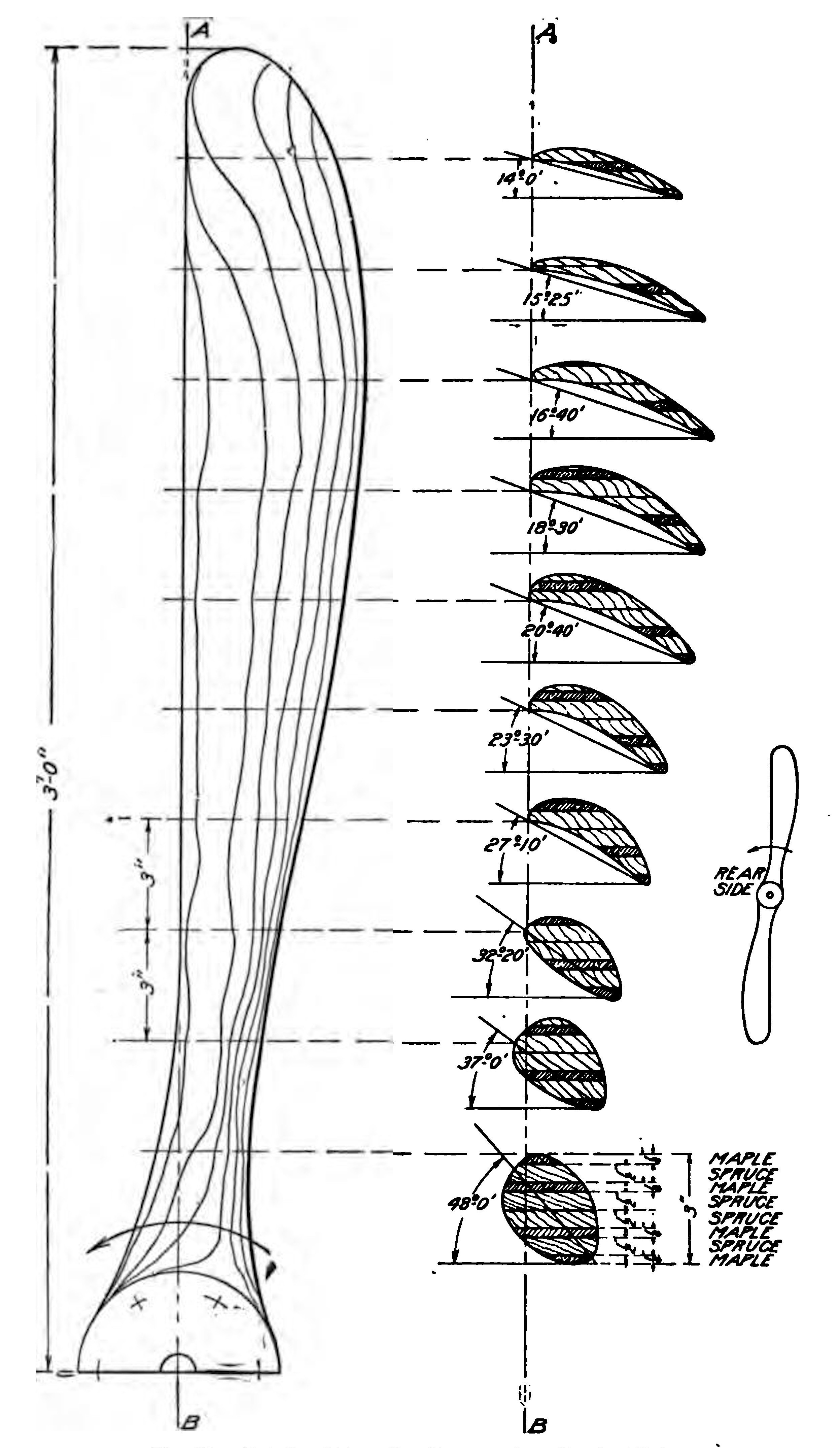
Fig. 21. Details of Propeller Construction, Curtiss Biplane
Shaping the Blades. Like the ribs, the propeller is made up of a number of laminations of boards finished true and securely glued, afterward being cut to the proper shape, though this process, of course, involves far more skill than in the former case. Spruce is the strongest wood for its weight, but it is soft and cracks easily. Maple, on the other hand, is tough and hard, so that it will be an advantage to alternate the layers of these woods with an extra maple board, in order to make both outside strips of the harder wood, so as to form a good backing for the steel flanges at the hub, the rear layer extending the full length of the thin rear edges of the blades. Other woods may be employed and frequently are used by propeller manufacturers, such as mahogany (not the grained wood used for furniture, but a cheaper grade which is much stronger), walnut, alternate spruce and whitewood, and others.
The boards should be selected with the greatest care so as to insure their being perfectly clear, i.e., absolutely free of knots, cross-grained streaks, or similar flaws, which would impair their strength and render them difficult to work smoothly. They should measure 6 inches wide by 6 feet 1 inch in length. Their surfaces must be finished perfectly true, so that they will come together uniformly all over the area on which they bear on one another, and the various pieces must be glued together with the most painstaking care. Have the glue hot, so that it will spread evenly, and see that it is of a uniform consistency, in order that it may be smoothly applied to every bit of the surface. They must then be clamped together under as much pressure as it is possible to apply to them with the means at hand, the rib press already described in detail forming an excellent tool for this purpose. Tighten up the nuts evenly a little at a time, avoiding the application of excessive or uneven pressure at one point, continuing the gradual tightening up process until it can not be carried any farther. This is to prevent the boards from assuming a curve in drying fast. Allow at least twenty-four hours for drying, during which period the laminated block should be kept in a cool, dry place at as even a temperature as possible.
Before undertaking the remainder of the work, all of which must be carried out by hand, with the exception of cutting the block to the outline of the propeller, which may be done with a band saw, a set of templates or gauges should be made from the drawings. These will be necessary as guides for finishing the propeller accurately. Draw the sections out full size on sheets of cardboard or tin and cut out along the curves, finally dividing each sheet into two parts, one for the upper side and one for the lower. Care must be taken to get the sides of the template square, and when they are used, the propeller should be laid on a perfectly true and flat block. Each template should be marked as it is finished, to indicate what part of the blade it is a gauge for. The work of cutting the laminated block down to the lines represented by the templates is carried out with the aid of the plane, spoke shave, and gouge. After the first roughing out to approximate the curvature of the finished propeller is completed, the cuts taken should be very fine, as it will be an easy matter to go too deep, thus spoiling the block and necessitating a new start with fresh material. For finishing, pieces of broken glass are employed to scrape the wood to a smooth surface, followed by coarse and finally by fine sandpaper.
Mounting. The hub should be of the same diameter as the flange on the engine crank shaft to which the flywheel was bolted, and should have its bolt holes drilled to correspond. To strengthen the hub, light steel plates of the same diameter are screwed to it, front and back, and the bolt holes drilled right through the metal and wood. This method of fastening is recommended where it is possible to substitute the propeller for the flywheel formerly on the engine, it being common practice to omit the use of the flywheel altogether. The writer does not recommend this, however, as the advantages of smoother running and more reliable operation gained by the use of a flywheel in addition to the propeller far more than offset any disadvantage represented by its weight. It will be noted that the Wright motors have always been equipped with a flywheel of ample size and weight and this is undoubtedly responsible, in some measure at least, for the fact that the Wright biplanes fly with considerably less power than is ordinarily employed for machines of the same size. If the motor selected be equipped with an unusually heavy flywheel, and particularly where the wheel is of comparatively small diameter, making it less effective as a balancer, it may be replaced with one of lighter weight and larger diameter. It may be possible to attach it by keying to the forward end of the crank shaft, thus leaving the flange from which the flywheel was taken free for mounting the propeller. An ordinary belt pulley will serve excellently as the new flywheel, as most of its weight is centered in its rim, but as the common cast-iron belt pulley of commerce is seldom intended to run at any such speed as that of an automobile motor, it should be examined carefully for flaws. Otherwise, there will be danger of its blunting with disastrous results under the influence of centrifugal force. Its diameter should not exceed 16 inches in order to keep its peripheral speed within reasonable limits. Where the mounting of the motor permits of its use, a wood pulley 18 to 20 inches in diameter with a steel band about 1/8 to 1/4-inch thick, shrunk on its periphery, may be employed. Most builders will ridicule the idea of a flywheel other than the propeller itself. "You do not need it; so why carry the extra weight?" will be their query. It is not absolutely necessary, but it is an advantage.
In case the flywheel of the engine selected is keyed to the crank shaft, or in case it is not possible to mount both the flywheel and the propeller on different ends of the crank shaft, some other expedient rather than that of bolting to the flange must be adopted. In such a case, the original flywheel, where practical to retain it, may be drilled and tapped and the propeller attached directly to it. Where the flywheel can not be kept, it will usually be found practical to cut off its rim and bolt the propeller either to the web or spokes, or to the flywheel hub, if it be cut down to the latter.
The drawing. Fig. 21, shows the rear or concave side of the propeller. From the viewpoint of a man standing in its wind and facing forward, it turns to the left, or anti-clockwise. On many of the propellers now on the market, the curved edge is designed to go first. This type may have greater advantages over that described, but the straight front edge propeller is easier for the amateur to make.
Mounting the Engine. Having completed the propeller, the next step is the mounting of the engine. Reference to the types available to the amateur aeroplane builder has already been made. There are a number of motors now on the market that have been designed specially for this purpose and not a few of them are of considerable merit. Their cost ranges from about $250 up to $2,500, but it may be possible to pick up a comparatively light-weight automobile motor second hand which will serve all purposes and which will cost far less than the cheapest aeronautic motor on the market. It must be capable of developing 30 actual horse-power at 1,000 to 1,200 r.p.m. and must not exceed 400 pounds complete with all accessories, such as the radiator and piping, magneto, water, oil, etc. Considerable weight may be saved on an automobile motor by removing the exhaust manifold and substituting a lighter flywheel for the one originally on the engine—or omitting it altogether, as just mentioned. A light-weight aeronautic radiator should be used in preference to the usual automobile radiator.
When placing the engine in position on the ash beams forming its bed or support, it must be borne in mind that the complete machine, with the operator in the aviator's seat, is designed to balance on a point about 1 1/2 feet back of the front edge of the main planes. As the operator and the motor represent much the larger part of the total weight, the balance may easily be regulated by moving them slightly forward or backward, as may be required. It will be necessary, of course, to place the engine far enough back in any case to permit the propeller blades to clear the planes. The actual installation of the engine itself will be an easy matter for anyone who has had any experience in either automobile or marine gasoline motor work. It is designed to be bolted to the two engine beams in the same manner as on the side members of the frame of an automobile, or the engine bed in a boat. Just in front of the engine is the best place for the gasoline tank, which should be cylindrical with tapering ends, to cut down its wind resistance. If the designer is not anxious to carry out points as fine as this, a light copper cylindrical tank may be purchased from stock. It should hold at least ten gallons of gasoline. In front of the tank is the radiator.
Controls. The controls may be located to conform to the builder's own ideas of accessibility and convenience. Usually the switch is placed on the steering column, and it may be of the ordinary knife variety, or one of the special switches made for this purpose, as taste may dictate. The throttle control and spark advance may either be in the form of pedals, working against springs, or of small levers working on a notched sector, at the side of the seat. The complete control, levers, and sector may be purchased ready to mount whenever desired, as they are made in this form for both automobile and marine work. This likewise applies to the wheel, which it would not pay the amateur to attempt to make.
Another pedal should work a brake on the front wheel, the brake shoe consisting of a strip of sheet steel, fastened at one end to the fore part of the skid and pressed against the wheel by a bamboo rod directly connected with the brake pedal. An emergency brake can also be made by loosely bolting a stout bar of steel on the skid near its rear end; one end of this bar is connected to a lever near the seat, so that when this lever is pulled back the other end of the bar tends to dig into the ground. As making a landing is one of the most difficult feats for the amateur aviator to master and sufficient space for a long run after alighting is not always available, these brakes will be found a very important feature of the machine.
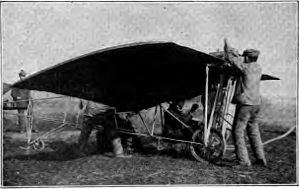
Fig. 22. Method of Starting the Engine of an Aeroplane
The engine is started by swinging the propeller, and this is an operation requiring far more caution than cranking an automobile motor. Both hands should be placed on the same blade. Fig. 22, and the latter should always be pulled downward—never upward. With the switch off, first turn the propeller over several times to fill the cylinders with gas, leaving it just ahead of dead center of one of the cylinders, and with one blade extending upward and to the left at a 45-degree angle. After closing the switch, take the left blade with both hands and swing it downward sharply, getting out of the way of the following blade as quickly as possible.
Tests. The first thing to be done after the propeller is finished and mounted on the engine is to test the combination, or power plant of the biplane, for speed and thrust, or pulling power. From these two quantities it will be easy to figure the power that the engine is delivering. The only instruments necessary are a spring balance reading to 300 pounds or over; a revolution counter, such as may be procured at any machinist's supply house for a dollar or two; and a watch. One end of the spring balance is fastened to the front end of the skid and the other to a heavy stake firmly driven in the ground a few feet back. The wheels of the biplane should be set on smooth boards so that they will not offer any resistance to the forward thrust. When the engine is started the spring balance will give a direct reading of the pull of the propeller.
With one observer noting the thrust, another should check the number of revolutions the engine is turning per minute. To do this, a small hole should previously have been countersunk in the hub of the propeller to receive the conical rubber tip of the revolution counter. The observer stands behind the propeller, watch in one hand and revolution counter in the other. At the beginning of the minute period, the counter is pressed firmly against the hub, and quickly withdrawn at the end of the minute. A stop watch is naturally an advantage for the purpose. The horse-power is figured as follows, assuming, for example, a thrust of 250 pounds at 1,200 r.p.m.
250 X 1200 X 3.5 X 100 / 33.000 X 85 = 37 h. p.
As before, the "100/85" allows for the slip and represents the efficiency of the propeller; 33,000 is the number of foot pounds per minute or the equivalent of one horse-power, and 3.5 is the pitch of the propeller.
Assembling the Biplane. Assembling the machine complete requires more space than is available in the average workshop. However, it is possible to assemble the sections of the planes in a comparatively small room, carrying the work far enough to make sure that everything will go together properly when the time comes for complete assembly at the testing ground. In this case, it is preferable to assemble the end sections first, standing them away when complete to make room for the central section, on which the running gear and outriggers are to be built up.
The builder will have decided by this time whether he will make his machine on the regular plan, with one main rib between each section, or on the quick-detachable plan, which has two main ribs on either side of the central section, as previously explained.
It is desirable to be able to assemble two sections at once and this should be possible anywhere as it requires a space only about 6 by 13 feet. Two wood 2X4's, about 12 feet long, should be nailed down on the blocks on the floor; make these level and parallel to each other at a distance of 3 feet 6 inches on centers, one being 3 inches higher than the other. Strips of wood should be nailed on them, so as to hold the main beams of the frame in place while assembling.
The two front and two rear beam sections are laid in place and joined with the sheet-steel sleeves, the flanges of the sleeves on the inner side of the beams. Then through the sleeves in the front beams, which are, of course, those on the higher bed, drill the holes for the strut socket bolts (1/4 inch). The holes for the outer ones go through the projecting ends of the beams; those for the inner ones are half in each of the two abutting beams. At the end where the central section joins on, a short length of wood of the same section may be inserted in the sleeve while drilling the hole. An assistant should hold the beams firmly together while the holes are being drilled.
Now lay in place the three main ribs belonging to the two sections under construction and fasten them at the front ends by putting in place the strut sockets for which the holes have been drilled, with a turnbuckle plate under each socket, Fig. 16. The strut socket bolt passes through the main rib and the beam. The bed on which the assembling is being done, should be cut when sufficiently under the joints to leave room for the projecting bolt ends. Set the ribs square with the front beams, then arrange the rear beams so that their joints come exactly under the ribs; clamp the ribs down and drill a true, vertical hole through the rib beam, holding the two sections of the beam together as before. Then put the rear strut sockets in place, using the angle washers previously described, above and below the rib.
When the quick-detachable plan is followed, the ribs at the inner ends of the double section, where they join the central section, should be bolted on an inch from the ends of the beam, using 1/4-inch stove bolts instead of the socket bolts. The sleeves should be slotted, so that they can slide off without removing these bolts, as the sleeves and ribs which occupy the position over the joints of the beams, belong to the central section.
The sections should now be strung up with the diagonal truss wires which will make them rigid enough to stand handling. The wires are attached at each end to the flange bolts of the sleeves. Either one or two turnbuckles may be used on each wire, as already explained; if but one turnbuckle be used, the other end of the wire may be conveniently attached to a strip of sheet steel bent double and drilled for the bolt, like the sheet-steel slip of a turnbuckle. The attachment, of whatever nature, should be put between the end and the flange of the sleeve, not between the two flanges.
Three or four ribs can be used on each section; four are preferable on sections of full 6-foot length. They are, of course, evenly spaced on centers. At the front ends, they are attached to the beam by wood screws through their flattened ferrules. The attachment to the rear beam is made with a slip of sheet steel measuring 1/2 by 3 inches, bent over the rib and fastened to the beam at each side with a wood screw. A long wire nail is driven through the rib itself on the beam.
Four double sections should be built up in this manner, the right and left upper and the right and left lower sections. Uppers and lowers are alike except for the inversion of the sockets in the upper sections. Rights and lefts differ in that the outer beams are long enough to fill up the sleeves, not leaving room for another beam to join on.
Inserting the struts in their sockets between the upper and lower sections of the same side will now form either of the two sides of the machine complete. Care should be taken to get the rear struts the proper length with respect to the front ones to bring the upper and lower planes parallel. The distance from the top of the lower front beam to the top of the upper front beam should be the same as the distance between the rows of bracing holes in the upper and lower main ribs just above and below the rear struts—about 4 feet 6 inches. It should hardly be necessary to mention that the thick edges of the struts come to the front—they are fish-shaped and a fish is thicker at the head than at the tail.
The truss wires may now be strung on in each square of the struts, beams, and main ribs, using turnbuckles as previously described. The wires should be taut enough to sing a low note when plucked between the thumb and forefinger. If the construction is carried out properly, the framework will stand square and true with an even tension on all the wires. It is permissible for the struts to slant backward a little as seen from the side, but all should be perfectly in line.
For adjusting the turnbuckles, the builder should make for himself a handy little tool usually termed a nipple wrench. It is simply a strip of steel 1 1/2 by 1/2 by 3/32 inches, with a notch cut in the middle of the long sides to fit the flattened ends of the turnbuckle nipples. This is much handier than the pliers and does not burr up the nipples.
It has been assumed in this description of the assembling that the builder is working in a limited space; if, on the contrary, he has room enough to set up the whole frame at once, the work will be much simpler. In this case, the construction bed should be 30 feet long. First build up the upper plane complete, standing it against the wall when finished; then build the lower plane, put the struts in their sockets, and lay on the upper plane complete.
Returning to the plan of assembly by sections, after the side sections or wings of the machine have been completed, the struts may be taken out and the sections laid aside. The middle section, to which the running gear and outriggers will be attached, is now to be built up in the same way. If the builder is following the plan in which there is one main rib between each section, it will be necessary to take off the four inner main ribs from the sections already completed, to be used at the ends of the central section. The plan drawing of the complete machine shows that the ribs of the central section are cut off just back of the rear beam to make room for the propeller. This is necessary in order to set the motor far enough forward to balance the machine properly. The small ribs in this section have the same curve but are cut off 10 inches shorter at their rear ends, and the stumps are smoothed down for ferrules like those for the other small ribs. In the plan which has one main rib between each section, the main rib on each side of the central section must be left full length. In the quick-detachable plan with two main ribs on each side of the central section, the inner ones, which really belong to this section, are cut off short like the small ribs.
In the drawing of the complete machine, the distance between the struts which carry the engine bed is shown as 2 feet. This is only approximate, as the distance must be varied to suit the motor employed. By this time, the builder will have decided what engine he is going to use—or can get—and should drill the holes for the sockets of these struts with due respect to the width of the engine's supporting feet or lugs, remembering that the engine bed beams go on the inside of the struts. In the drawing of the running gear. Fig. 17, the distance between the engine-bed struts has been designated A. The distances, B, on each side are, of course, approximately (6'— 2*A*), whatever A may be.
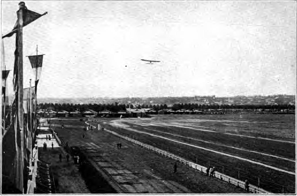
VIEW OF THE FRENCH AVIATION GROUNDS SHOWING THE HANGARS RANGED ALONG THE EDGES OF THE FIELD This Photograph Protected By International Copyright
EXAMINATION PAPER
BUILDING AND FLYING AN
AEROPLANE
PART I
Read Carefully: Place your name and full address at the head of the paper. Any cheap, light paper like the sample previously sent you may be used. Do not crowd your work, but arrange it neatly and legibly. Do not copy the answers from the Instruction Paper; use your own words so that we may be sure that you understand the subject.
What type of machine, biplane or monoplane, makes the best glider and why?
Give the dimensions of a glider which will support a man's weight.
In a glider which has no rudder, how is the machine controlled?
Give carefully the details of the start in making a glide.
In what direction relative to the wind should a glide be made? Justify your answer.
How must the stability and balance of a glider in flight be controlled?
State the proper conditions for a successful glide.
Give the essential characteristics of a Curtiss aeroplane, defining the various parts.
Describe briefly the details of construction of the main supporting surfaces of a Curtiss.
Draw a diagram of the assembled planes showing how the struts and cross wires are placed to give the required rigidity.
Give the details of the running gear of the Curtiss.
What is the office of the Curtiss ailerons and how are they controlled from the operator's seat? Draw sketch.
Describe the details of the front and rear outriggers.
What type of propeller is advised for the Curtiss? Give the details of its construction.
Describe carefully the manner in which a propeller should move through the air in order to give the maximum propulsion.
What determines the exact location of the motor in the aeroplane?
Give correct method of starting the motor when ready for a flight.
What tests should be conducted before a flight is undertaken?
After completing the work, add and sign the following statement:
I hereby certify that the above work is entirely my own.
(Signed)