Volume 24 — CHAPTER VI.
Reading edition
THE STEAM-ENGINE OF TO-DAY.
... “And, last of all, with inimitable power, and ‘with whirlwind sound,’ comes the potent agency of steam. In comparison with the past, what centuries of improvement has this single agent comprised in the short compass of fifty years! Everywhere practicable, everywhere efficient, it has an arm a thousand times stronger than that of Hercules, and to which human ingenuity is capable of fitting a thousand times as many hands as belonged to Briareus. Steam is found in triumphant operation on the seas; and, under the influence of its strong propulsion, the gallant ship—
‘Against the wind, against the tide, Still steadies with an upright keel.’
It is on the rivers, and the boatman may repose on his oars; it is on highways, and exerts itself along the courses of land-conveyance; it is at the bottom of mines, a thousand feet below the earth’s surface; it is in the mills, and in the workshops of the trades. It rows, it pumps, it excavates, it carries, it draws, it lifts, it hammers, it spins, it weaves, it prints. It seems to say to men, at least to the class of artisans: ‘Leave off your manual labor; give over your bodily toil; bestow but your skill and reason to the directing of my power, and I will bear the toil, with no muscle to grow weary, no nerve to relax, no breast to feel faintness!’ What further improvement may still be made in the use of this astonishing power it is impossible to know, and it were vain to conjecture. What we do know is, that it has most essentially altered the face of affairs, and that no visible limit yet appears beyond which its progress is seen to be impossible.”—Daniel Webster.
The Period of Refinement—1850 to Date.
By the middle of the present century, as we have now seen, the steam-engine had been applied, and successfully, to every great purpose for which it was fitted. Its first application was to the elevation of water; it next was applied to the driving of mills and machinery; and it finally became the great propelling power in transportation by land and by sea.
At the beginning of the period to which we are now come, these applications of steam-power had become familiar both to the engineer and to the public. The forms of engine adapted to each purpose had been determined, and had become usually standard. Every type of the modern steam-engine had assumed, more or less closely, the form and proportions which are now familiar; and the most intelligent designers and builders had been taught—by experience rather than by theory, for the theory of the steam-engine had then been but little investigated, and the principles and laws of thermo-dynamics had not been traced in their application to this engine—the principles of construction essential to successful practice, and were gradually learning the relative standing of the many forms of steam-engine, from among which have been preserved a few specially fitted for certain specific methods of utilization of power.
During the years succeeding the date 1850, therefore, the growth of the steam-engine had been, not a change of standard type, or the addition of new parts, but a gradual improvement in forms, proportions, and arrangements of details; and this period has been marked by the dying out of the forms of engine least fitted to succeed in competition with others, and the retention of the latter has been an example of “the survival of the fittest.” This has therefore been a Period of Refinement.
During this period invention has been confined to details; it has produced new forms of parts, new arrangements of details; it has devised an immense variety of valves, valve-motions, regulating apparatus, and a still greater variety of steam-boilers and of attachments, essential and non-essential, to both engines and boilers. The great majority of these peculiar devices have been of no value, and very many of the best of them have been found to have about equal value. All the well-known and successful forms of engine, when equally well designed and constructed and equally well managed, are of very nearly equal efficiency; all of the best-known types of steam-boiler, where given equal proportions of grate to heating-surface and equally well designed, with a view to securing a good draught and a good circulation of water, have been found to give very nearly equally good results; and it has become evident that a good knowledge of principles and of practice, on the part of the designer, the constructor, and the manager of the boiler, is essential in the endeavor to achieve economical success; that good engineering is demanded, rather than great ingenuity. The inventor has been superseded here by the engineer.
The knowledge acquired in the time of Watt, of the essential principles of steam-engine construction, has since become generally familiar to the better class of engineers. It has led to the selection of simple, strong, and durable forms of engine and boiler, to the introduction of various kinds of valves and of valve-gearing, capable of adjustment to any desired range of expansive working, and to the attachment of efficient forms of governor to regulate the speed of the engine, by determining automatically the point of cut-off which will, at any instant, best adjust the energy exerted by the expanding steam to the demand made by the work to be done.
The value of high pressures and considerable expansion was recognized as long ago as in the early part of the present century, and Watt, by combining skillfully the several principal parts of the steam-engine, gave it very nearly the shape which it has to-day. The compound engine, even, as has been seen, was invented by contemporaries of Watt, and the only important modifications since his time have occurred in details. The introduction of the “drop cut-off,” the attachment of the governor to the expansion-apparatus in such a manner as to determine the degree of expansion, the improvement of proportions, the introduction of higher steam and greater expansion, the improvement of the marine engine by the adoption of surface-condensation, in addition to these other changes, and the introduction of the double-cylinder engine, after the elevation of steam-pressure and increase of expansion had gone so far as to justify its use, are the changes, therefore, which have taken place during this last quarter-century. It began then to be generally understood that expansion of steam produced economy, and mechanics and inventors vied with each other in the effort to obtain a form of valve-gear which should secure the immense saving which an abstract consideration of the expansion of gases according to Marriotte’s law would seem to promise. The counteracting phenomena of internal condensation and reëvaporation, of the losses of heat externally and internally, and of the effect of defective vacuum, defective distribution of steam, and of back-pressure, were either unobserved or were entirely overlooked.
It was many years, therefore, before engine-builders became convinced that no improvement upon existing forms of expansion-gear could secure even an approximation to theoretical efficiency.
The fact thus learned, that the benefit of expansive working has a limit which is very soon reached in ordinary practice, was not then, and has only recently become, generally known among our steam-engine builders, and for several years, during the period upon which we now enter, there continued the keenest competition between makers of rival forms of expansion-gear, and inventors were continually endeavoring to produce something which should far excel any previously-existing device.
In Europe, as in the United States, efforts to “improve” standard designs have usually resulted in injuring their efficiency, and in simply adding to the first cost and running expense of the engines, without securing a marked increase in economy in the consumption of steam.
Section I.—Stationary Engines.
“Stationary Engines” had been applied to the operation of mill-machinery, as has been seen, by Watt and by Murdoch, his assistant and pupil; and Watt’s competitors, in Great Britain and abroad, had made considerable progress before the death of the great engineer, in its adaptation to its work. In the United States, Oliver Evans had introduced the non-condensing high-pressure stationary engine, which was the progenitor of the standard engine of that type which is now used far more generally than any other form. These engines were at first rude in design, badly proportioned, rough and inaccurate as to workmanship, and uneconomical in their consumption of fuel. Gradually, however, when made by reputable builders, they assumed neat and strong shapes, good proportions, and were well made and of excellent materials, doing their work with comparatively little waste of heat or of fuel.
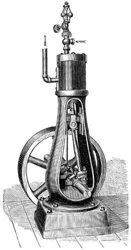
Fig. 93.—Vertical Stationary Steam-Engine.
One of the neatest and best modern designs of stationary engine for small powers is seen in Fig. 93, which represents a “vertical direct-acting engine,” with base-plate—a form which is a favorite with many engineers.
The engine shown in the engraving consists of two principal parts, the cylinder and the frame, which is a tapering column having openings in the sides, to allow free access to all the working parts within. The slides and pillow-blocks are cast with the column, so that they cannot become loose or out of line; the rubbing surfaces are large and easily lubricated. Owing to the vertical position, there is no tendency to side wear of cylinder or piston. The packing-rings are self-adjusting, and work free but tight. The crank is counterbalanced; the crank-pin, cross-head pin, piston-rod, valve-stem, etc., are made of steel; all the bearing surfaces are made extra large, and are accurately fitted; and the best quality of Babbitt-metal only used for the journal-bearings.
The smaller sizes of these engines, from 2 to 10 horse-power, have both pillow-blocks cast in the frame, giving a bearing each side of the double cranks. They are built by some constructors in quantities, and parts duplicated by special machinery (as in fire-arms and sewing-machines), which secures great accuracy and uniformity of workmanship, and allows of any part being quickly and cheaply replaced, when worn or broken by accident. The next figure is a vertical section through the same engine.
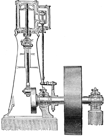
Fig. 94.—Vertical Stationary Steam-Engine. Section.
Engines fitted with the ordinary rigid bearings require to be erected on a firm foundation, and to be kept in perfect line. If, by the settling of the foundation, or from any other cause, they get out of line, heating, cutting, and thumping result. To obviate this, modern engines are often fitted with self-adjusting bearings throughout; this gives the engine great flexibility and freedom from friction. The accompanying cuts show clearly how this is accomplished. The pillow-block has a spherical shell turned and fitted into the spherically-bored pillow-block, thus allowing a slight angular motion in any direction. The connecting-rod is forged in a single piece, without straps, gibs, or key, and is mortised through at each end for the reception of the brass boxes, which are curved on their backs, and fit the cheek-pieces, between which they can turn to adjust themselves to the pins, in the plane of the axis of the rod. The adjustment for wear is made by wedge-blocks and set screws, as shown, and they are so constructed that the parts cannot get loose and cause a break-down. The cross-head has adjustable gibs on each side, turned to fit the slides, which are cast solidly in the frame, and bored out exactly in the line with the cylinder. This permits it freely to turn on its axis, and, in connection with the adjustable boxes in the connecting-rod, allows a perfect self-adjustment to the line of the crank-pin. The out-board bearing may be moved an inch or more out of position in any direction, without detriment to the running of the engine, all bearings accommodating themselves perfectly to whatever position the shaft may assume.
The ports and valve-passages are proportioned as in locomotive practice. The valve-seat is adapted to the ordinary plain slide or D-valve, should it be preferred, but the balanced piston slide-valve works with equal ease whether the steam-pressure is 10 or 100 pounds, and at the same time gives double steam and exhaust openings, which greatly facilitates the entrance of the steam to, and its escape from, the cylinder, thus securing a nearer approach to boiler-pressure and a less back-pressure, saving the power required to work an ordinary valve, and reducing the wear of valve-gear.
This is a type of engine frequently seen in the United States, but more rarely in Europe. It is an excellent form of engine. The vertical direct-acting engine is sometimes, though rarely, built of very considerable size, and these large engines are more frequently seen in rolling-mills than elsewhere.
Where much power is required, the stationary engine is usually an horizontal direct-acting engine, having a more or less effective cut-off valve-gear, according to the size of engine and the cost of fuel. A good example of the simpler form of this kind of engine is the small horizontal slide-valve engine, with independent cut-off valve riding on the back of the main valve—a combination generally known among engineers as the Meyer system of valve-gear. This form of steam-engine is a very effective machine, and does excellent work when properly proportioned to yield the required amount of power. It is well adapted to an expansion of from four to five times. Its disadvantages are the difficulty which it presents in the attachment of the regulator, to determine the point of cut-off by the heavy work which it throws upon the governor when attached, and the rather inflexible character of the device as an expansive valve-gear. The best examples of this class of engine have neat heavy bed-plates, well-designed cylinders and details, smooth-working valve-gear, the expansion-valve adjusted by a right and left hand screw, and regulation secured by the attachment of the governor to the throttle-valve.
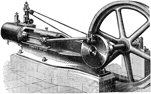
Fig. 95.—Horizontal Stationary Steam-Engine.
The engine shown in the accompanying illustration (Fig. 95) is an example of an excellent British stationary steam-engine. It is simple, strong, and efficient. The frame, front cylinder-head, cross-head guides, and crank-shaft “plumber-block,” are cast in one piece, as has so generally been done in the United States for a long time by some of our manufacturers. The cylinder is secured against the end of the bed-plate, as was first done by Corliss. The crank-pin is set in a counterbalanced disk. The valve-gear is simple, and the governor effective, and provided with a safety-device to prevent injury by the breaking of the governor-belt. An engine of this kind of 10 inches diameter of cylinder, 20 inches stroke of piston, is rated by the builders at about 25 horse-power; a similar engine 30 inches in diameter of cylinder would yield from 225 to 250 horse-power. In this example, all parts are made to exact size by gauges standardized to Whitworth’s sizes.
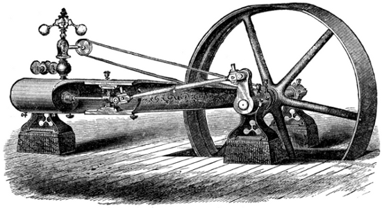
Fig. 96.—Horizontal Stationary Steam-Engine.
In American engines (as is seen in Fig. 96), usually, two supports are placed—the one under the latter bearing, and the other under the cylinder—to take the weight of the engine; and through them it is secured to the foundation. As in the vertical engine already described, a valve is sometimes used, consisting of two pistons connected by a rod, and worked by an ordinary eccentric. By a simple arrangement these pistons have always the same pressure inside as out, which prevents any leakage or blowing through; and they are said always to work equally as well and free from friction under 150 pounds pressure as under 10 pounds per square inch, and to require no adjustment. It is more usual, however, to adopt the three-ported valve used on locomotives, with (frequently) a cut-off valve on the back of this main valve, which cut-off valve is adjusted either by hand or by the governor.
Engines of the class just described are especially well fitted, by their simplicity, compactness, and solidity, to work at the high piston-speeds which are gradually becoming generally adopted in the effort to attain increased economy of fuel by the reduction of the immense losses of heat which occur in the expansion of steam in the metallic cylinders through which we are now compelled to work it.
One of the best known of recent engines is the Allen engine, a steam-engine having the same general arrangement of parts seen in the above illustration, but fitted with a peculiar valve-gear, and having proportions of parts which are especially calculated to secure smoothness of motion and uniformity of pressure on crank-pin and journals, at speeds so high that the inertia of the reciprocating parts becomes a seriously-important element in the calculation of the distribution of stresses and their effect on the dynamics of the machine.
In the Allen engine,[85] the cylinder and frame are connected as in the engine seen above, and the crank-disk, shaft-bearings, and other principal details, are not essentially different. The valve-gear[86] differs in having four valves, one at each end on the steam as well as on the exhaust side, all of which are balanced and work with very little resistance. These valves are not detachable, but are driven by a link attached to and moved by an eccentric on the main shaft, the position of the valve-rod attachment to which link is determined by the governor, and the degree of expansion is thus adjusted to the work of the engine. The engine has usually a short stroke, not exceeding twice the diameter of cylinder, and is driven at very high speed, generally averaging from 600 to 800 feet per minute.[87] This high piston-speed and short stroke give very great velocity of rotation. The effect is, therefore, to produce an exceptional smoothness of motion, while permitting the use of small fly-wheels. Its short stroke enables entire solidity to be attained in a bed of rigid form, making it a very completely self-contained engine, adapted to the heaviest work, and requiring only a small foundation.
The journals of the shaft, and all cylindrical wearing surfaces, are finished by grinding in a manner that leaves them perfectly round. The crank-pin and cross-head pin are hardened before being ground. The joints of the valve-gear consist of pins turning in solid ferrules in the rod-ends, both hardened and ground. After years of constant use thus, no wear occasioning lost time in the valve-movements has been detected.
High speed and short strokes are essential elements of economy. It is now well understood that all the surfaces with which the steam comes in contact condense it.
Obviously, one way to diminish this loss is to reduce the extent of surface to which the steam is exposed. In engines of high speed and short stroke, the surfaces with which the steam comes in contact, while doing a given amount of work, present less area than in ordinary engines running at low speed. Where great steadiness of motion is desired, the expense of coupled engines is often incurred. Quick-running engines do not require to be coupled; a single engine may give greater uniformity of motion than is usually obtained with coupled engines at ordinary speeds. The ports and valve-movements, the weight of the reciprocating parts, and the size and weight of the fly-wheels, should be calculated expressly for the speeds chosen.
The economy of the engine here described is unexcelled by the best of the more familiar “drop cut-off” engines.
An engine reported upon by a committee of the American Institute, of which Dr. Barnard was chairman, was non-condensing, 16 inches in diameter of cylinder, 30 inches stroke, making 125 revolutions per minute, and developed over 125 horse-power with 75 pounds of steam in the boiler, using 253∕4 pounds of steam per indicated horse-power, and 2.87 pounds of coal—an extraordinarily good performance for an engine of such small power.
The governor used on this engine is known as the Porter governor. It is given great power and delicacy by weighting it down, and thus obtaining a high velocity of rotation, and by suspending the balls from forked arms, which are given each two bearing-pins separated laterally so far as to permit considerable force to be exerted in changing speeds without cramping those bearings sufficiently to seriously impair the sensitiveness of the governor. This engine as a whole may be regarded as a good representative of the high-speed engine of to-day.
Since this change in the direction of high speeds has already gone so far that the “drop cut-off” is sometimes inapplicable, in consequence of the fact that the piston would, were such a valve-gear adopted, reach the end of its stroke before the detached valve could reach its seat; and since this progress is only limited by our attainments in mechanical skill and accuracy, it seems probable that the “positive-motion expansion-gear” type of engine will ultimately supersede the now standard “drop cut-off engine.”
The best known and most generally used class of stationary engines at the present time is, however, that which has the so-called “drop cut-off,” or “detachable valve-gear.” The oldest well-known form of valve-motion of this description now in use is that known as the Sickels cut-off, patented by Frederick E. Sickels, an American mechanic, about the year 1841, and also built by Hogg, of New York, who placed it upon the engine of the steamer South America. The invention is claimed for both Hogg and Sickels. It was introduced by the inventor in a form which especially adapted it to use with the beam-engine used on the Eastern waters of the United States, and was adapted to stationary engines by Messrs. Thurston, Greene & Co., of Providence, R. I., who made use of it for some years before any other form of “drop cut-off” came into general use. The Sickels cut-off consisted of a set of steam-valves, usually independent of the exhaust-valves, and each raised by a catch, which could be thrown out, at the proper moment, by a wedge with which it came in contact as it rose with the opening valve. This wedge, or other equivalent device, was so adjusted that the valve should be detached and fall to its seat when the piston reached that point in its movement, after taking steam, at which expansion was to commence. From this point, no steam entering the cylinder, the piston was impelled by the expanding vapor. The valve was usually the double-poppet. Sickels subsequently invented what was called the “beam-motion,” to detach the valve at any point in the stroke. As at first arranged, the valve could only be detached during the earlier half-stroke, since at mid-stroke the direction of motion of the eccentric rod was reversed and the valve began to descend. By introducing a “wiper” having a motion transverse to that of the valve and its catch, and by giving this wiper a motion coincident with that of the piston by connecting it with the beam or other part of the engine moving with the piston, he obtained a kinematic combination which permitted the valve to be detached at any point in the stroke, adding a very simple contrivance which enabled the attendant to set the wiper so that it should strike the catch at any time during the forward movement of the “beam-motion.”
On stationary engines, the point of cut-off was afterward determined by the governor, which was made to operate the detaching mechanism, the combination forming what is sometimes called an “automatic” cut-off. The attachment of the governor so as to determine the degree of expansion had been proposed before Sickels’s time. One of the earliest of these contrivances was that of Zachariah Allen, in 1834, using a cut-off valve independent of the steam-valve. The first to so attach the governor to a drop cut-off valve-motion was George H. Corliss, who made it a feature of the Corliss valve-gear in 1849. In the year 1855, N. T. Greene introduced a form of expansion-gear, in which he combined the range of the Sickels beam-motion device with the expansion-adjustment gained by the attachment of the governor, and with the advantages of flat slide-valves at all ports—both steam and exhaust.
Many other ingenious forms of expansion valve-gear have been invented, and several have been introduced, which, properly designed and proportioned to well-planned engines, and with good construction and management, should give economical results little if at all inferior to those just named. Among the most ingenious of these later devices is that of Babcock & Wilcox, in which a very small auxiliary steam-cylinder and piston is employed to throw the cut-off valve over its port at the instant at which the steam is to be cut off. A very beautiful form of isochronous governor is used on this engine, to regulate the speed of the engine by determining the point of cut-off.
In Wright’s engine, the expansion is adjusted by the movement, by the regulator, of cams which operate the steam-valves so that they shall hold the valve open a longer or shorter time, as required.
Since compactness and lightness are not as essential as in portable, locomotive, and marine engines, the parts are arranged, in stationary engines, with a view simply to securing efficiency, and the design is determined by circumstances. It was formerly usual to adopt the condensing engine in mills, and wherever a stationary engine was required. In Europe generally, and to some extent in the United States, where a supply of condensing water is obtainable, condensing engines and moderate steam-pressures are still employed. But this type of engine is gradually becoming superseded by the high-pressure condensing engine, with considerable expansion, and with an expansion-gear in which the point of cut-off is determined by the governor.
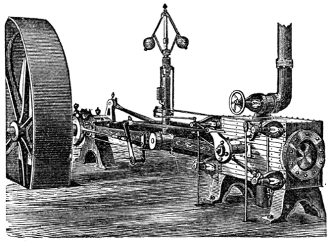
Fig. 97.—Corliss Engine.
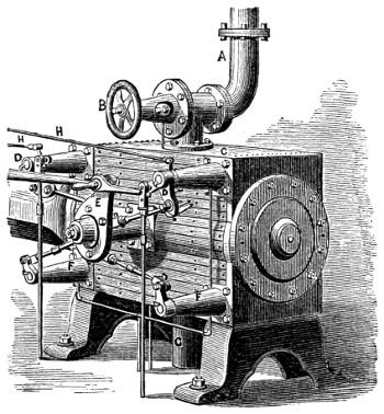
Fig. 98—Corliss Engine Valve-Motion.
The best-known engine of this class is the Corliss engine, which is very extensively used in the United States, and which has been copied very generally by European builders. Fig. 97 represents the Corliss engine. The horizontal steam-cylinder is bolted firmly to the end of the frame, which is so formed as to transmit the strain to the main journal with the greatest directness. The frame carries the guides for the cross-head, which are both in the same vertical plane. The valves are four in number, a steam and an exhaust valve being placed at each end of the steam-cylinder. Short steam-passages are thus secured, and this diminution of clearance is a source of some economy. Both sets of valves are driven by an eccentric operating a disk or wrist-plate, E (Fig. 98), which vibrates on a pin projecting from the cylinder. Short links reaching from this wrist-plate to the several valves, D D, F F, move them with a peculiarly varying motion, opening and closing them rapidly, and moving them quite slowly when the port is either nearly open or almost closed. This effect is ingeniously secured by so placing the pins on the wrist-plate that their line of motion becomes nearly transverse to the direction of the valve-links when the limit of movement is approached. The links connecting the wrist-plate with the arms moving the steam-valves have catches at their extremities, which are disengaged by coming in contact, as the arm swings around with the valve-stem, with a cam adjusted by the governor. This adjustment permits the steam to follow the piston farther when the engine is caused to “slow down,” and thus tends to restore the proper speed. It disengages the steam-valve earlier, and expands the steam to a greater extent, when the engine begins to run above the proper speed. When the catch is thrown out, the valve is closed by a weight or a strong spring. To prevent jar when the motion of the valve is checked, a “dash-pot” is used, invented originally by F. E. Sickels. This is a vessel having a nicely-fitted piston, which is received by a “cushion” of water or air when the piston suddenly enters the cylinder at the end of the valve-movement. In the original water dash-pot of Sickels, the cylinder is vertical, and the plunger or piston descends upon a small body of water confined in the base of the dash-pot. Corliss’s air dash-pot is now often set horizontally.
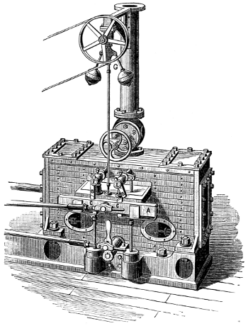
Fig. 99.—Greene Engine.
In the Greene steam-engine (Fig. 99), the valves are four in number, as in the Corliss. The cut-off gear consists of a bar, A, moved by the steam-eccentric in a direction parallel with the centre-line of the cylinder and nearly coincident as to time with the piston. On this bar are tappets, C C, supported by springs and adjustable in height by the governor, G. These tappets engage the arms B B, on the ends of rock-shafts, E E, which move the steam-valves and remain in contact with them a longer or shorter time, and holding the valve open during a greater or less part of the piston-stroke, as the governor permits the tappets to rise with diminishing engine-speed, or forces them down as speed increases. The exhaust-valves are moved by an independent eccentric rod, which is itself moved by an eccentric set, as is usual with the Corliss and with other engines generally, at right angles with the crank. This engine, in consequence of the independence of the steam-eccentric, and of the contemporary movement of steam valve-motion and steam-piston, is capable of cutting off at any point from beginning to nearly the end of the stroke. The usual arrangement, by which steam and exhaust valves are moved by the same eccentric, only permits expansion with the range from the beginning to half-stroke. In the Corliss engine the latter construction is retained, with the object, in part, of securing a means of closing the valve by a “positive motion,” should, by any accident, the closing not be effected by the weight or spring usually relied upon.
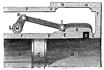
Fig. 100.—Thurston’s Greene-Engine Valve-Gear.
The steam-valve of the Greene engine, as designed by the author, is seen in Fig. 100, where the valve, G H, covering the port, D, in the steam-cylinder, A B, is moved by the rod, J J, connected to the rock-shaft, M, by the arm, L K. The line, K I, should, when carried out, intersect the valve-face at its middle point, under G.
The characteristics of the American stationary engine, therefore, are high steam-pressure without condensation, an expansion valve-gear with drop cut-off adjustable by the governor, high piston-speed, and lightness combined with strength of construction. The pressure most commonly adopted in the boilers which furnish steam to this type of engine is from 75 to 80 pounds per square inch; but a pressure of 100 pounds is not infrequently carried, and the latter pressure may be regarded as a “mean maximum,” corresponding to a pressure of 60 pounds at about the commencement of the period here considered—1850.
Very much greater pressures have, however, been adopted by some makers, and immensely “higher steam” has been experimented with by several engineers. As early as 1823, Jacob Perkins[88] commenced experimenting with steam of very great tension. As has already been stated, the usual pressure at the time of Watt was but a few pounds—5 or 7—in excess of that of the atmosphere. Evans, Trevithick, and Stevens, had previously worked steam at pressures of from 50 to 75 pounds per square inch, and pressures on the Western rivers and elsewhere in the United States had already been raised to 100 or 150 pounds, and explosions were becoming alarmingly frequent.
Perkins’s experimental apparatus consisted of a copper boiler, of a capacity of about one cubic foot, having sides 3 inches in thickness. It was closed at the bottom and top, and had five small pipes leading from the upper head. This was placed in a furnace kept at a high temperature by a forced combustion. Safety-valves loaded respectively to 425 and 550 pounds per square inch were placed on each of two of the steam-pipes.
Perkins used the steam generated under these great pressures in a little engine having a piston 2 inches in diameter and a stroke of 1 foot. It was rated at 10 horse-power.[89]
In the year 1827, Perkins had attained working pressures, in a single-acting, single-cylinder engine, of upward of 800 pounds per square inch. At pressures exceeding 200 pounds, he had much trouble in securing effective lubrication, as all oils charred and decomposed at the high temperatures then unavoidably encountered, and he finally succeeded in evading this seemingly insurmountable obstacle by using for rubbing parts a peculiar alloy which required no lubrication, and which became so beautifully polished, after some wear, that the friction was less than where lubricants were used. At these high pressures Perkins seems to have met with no other serious difficulty. He condensed the exhaust-steam and returned it to the boiler, but did not attempt to create a vacuum in his condenser, and therefore needed no air-pump. Steam was cut off at one-eighth stroke.
In the same year, Perkins made a compound engine on the Woolf plan, and adopted a pressure of 1,400 pounds, expanding eight times. In still another engine, intended for a steam-vessel, Perkins adopted, or proposed to adopt, 2,000 pounds pressure, cutting off the admission at one-sixteenth, in single-acting engines of 6 inches diameter of cylinder and 20 inches stroke of piston. The steam did not retain boiler-pressure at the cylinder, and this engine was only rated at 30 horse-power.[90]
Stuart follows a description of Perkins’s work in the improvement of the steam-engine and the introduction of steam-artillery by the remark:
“ ... No other mechanic of the day has done more to illustrate an obscure branch of philosophy by a series of difficult, dangerous, and expensive experiments; no one’s labors have been more deserving of cheering encouragement, and no one has received less. Even in their present state, his experiments are opening new fields for philosophical research, and his mechanism bids fair to introduce a new style into the proportions, construction, and form, of steam-machinery.”
Perkins’s experience was no exception to the general rule, which denies to nearly all inventors a fair return for the benefits which they confer upon mankind.
Another engineer, a few years later, was also successful in controlling and working steam under much higher pressures than are even now in use. This was Dr. Ernst Alban, a distinguished German engine-builder, of Plau, Mecklenburg, and an admirer of Oliver Evans, in whose path he, a generation later, advanced far beyond that great pioneer. Writing in 1843, he describes a system of engine and boiler construction, with which he used steam under pressures about equal to those experimentally worked by Jacob Perkins, Evans’s American successor. Alban’s treatise was translated and printed in Great Britain,[91] four years later.
Alban, on one occasion, used steam of 1,000 pounds pressure. His boilers were similar in general form to the boiler patented by Stevens in 1805, but the tubes were horizontal instead of vertical. He evaporated from 8 to 10 pounds of water into steam of 600 to 800 pounds pressure with each pound of coal. He states that the difficulty met by Perkins—the decomposition of lubricants in the steam-cylinder—did not present itself in his experiments, even when working steam at a pressure of 600 pounds on the square inch, and he found that less lubrication was needed at such high pressures than in ordinary practice. Alban expanded his steam about as much as Evans, in his usual practice, carrying a pressure of 150 pounds, and cutting off at one-third; he adopted greatly increased piston-speed, attaining 300 feet per minute, at a time when common practice had only reached 200 feet. He usually built an oscillating engine, and rarely attached a condenser. The valve was the locomotive-slide.[92] The stroke was made short to secure strength, compactness, cheapness, and high speed of rotation; but Alban does not seem to have understood the principles controlling the form and proportions of the expansive engine, or the necessity of adopting considerable expansion in order to secure economy in working steam of great tension, and therefore was, apparently, not aware of the advantages of a long stroke in reducing losses by “dead-space,” in reducing risk of annoyance by hot journals, or in enabling high piston-speeds to be adopted. He seems never to have attained a sufficiently high speed of piston to become aware that the oscillating cylinder cannot be used at speeds perfectly practicable with the fixed cylinder.
Alban states that one of his smallest engines, having a cylinder 41∕2 inches in diameter and 1 foot stroke of piston, with a piston-speed of but 140 to 160 feet per minute, developed 4 horse-power, with a consumption of 5.3 pounds of coal per hour. This is a good result for so small an amount of work, and for an engine working at so low a speed of piston. An engine of 30 horse-power, also working very slowly, required but 4.1 pounds of coal per hour per horse-power.
The work of Perkins and of Alban, like that of their predecessors, Evans, Stevens, and Trevithick, was, however, the work of engineers who were far ahead of their time. The general practice, up to the time which marked the beginning of the modern “period of refinement,” had been but gradually approximating that just described. Higher pressures were slowly approached; higher piston-speeds came slowly into use; greater expansion was gradually adopted; the causes of losses of heat were finally discovered, and steam-jacketing and external non-conducting coverings were more and more generally applied as builders became more familiar with their work. The “compound engine” was now and then adopted; and each experiment, made with higher steam and greater expansion, was more nearly successful than the last.
Finally, all these methods of securing economy became recognized, and the reasons for their adoption became known. It then remained, as the final step in this progression, to combine all these requisites of economical working in a double-cylinder engine, steam-jacketed, well protected by non-conducting coverings, working steam of high pressure, and with considerable expansion at high piston-speed. This is now done by the best builders.
One of the best examples of this type of engine is that constructed by the sons of Jacob Perkins, who continued the work of their father after his death. Their engines are single-acting, and the small or high-pressure cylinder is placed on the top of the larger or low-pressure cylinder. The valves are worked by rotating stems, and the loss of heat and burning of packing incident to the use of the common method are thus avoided. The stuffing-boxes are placed at the end of long sleeves, closely surrounding the vertical valve-stems also, and the water of condensation which collects in these sleeves is an additional and thorough protection against excessively high temperature at the packing. The piston-rings are made of the alloy which has been found to require no lubrication.
Steam is usually worked at from 250 to 450 pounds, and is generated in boilers composed of small tubes three inches in diameter and three-eighths of an inch thick, which are tested under a pressure of 2,500 pounds per square inch. The safety-valve is usually loaded to 400 pounds. The boiler is fed with distilled water, obtained principally by condensation of the exhaust-steam, any deficiency being made up by the addition of water from a distilling apparatus. Under these conditions, but 11∕4 pound of coal is consumed per hour and per horse-power.
The Pumping-Engine in use at the present time has passed through a series of changes not differing much from that which has been traced with the stationary mill-engine. The Cornish engine is still used to some extent for supplying water to towns, and is retained at deep mines. The modern Cornish engine differs very little from that of the time of Watt, except in the proportions of parts and the form of its details. Steam-pressures are carried which were never reached during the preceding period, and, by careful adjustment of well-set and well-proportioned valves and gearing, the engine has been made to work rather more rapidly, and to do considerably more work. It still remains, however, a large, costly, and awkward contrivance, requiring expensive foundations, and demanding exceptional care, skill, and experience in management. It is gradually going out of use. This engine, as now constructed by good builders, is shown in section in Fig. 101.
A comparison with the Watt engine of a century earlier will at once enable any one to appreciate the extent to which changes may be made in perfecting a machine, even after it has become complete, so far as supplying it with all essential parts can complete it.
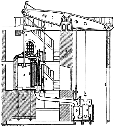
Fig. 101.—Cornish Pumping-Engine, 1880.
In the figure, A is the cylinder, taking steam from the boiler through the steam-passage, M. The steam is first admitted above the piston, B, driving it rapidly downward and raising the pump-rod, E. At an early period in the stroke the admission of steam is checked by the sudden closing of the induction-valve at M, and the stroke is completed under the action of expanding steam assisted by the inertia of the heavy parts already in motion. The necessary weight and inertia is afforded, in many cases, where the engine is applied to the pumping of deep mines, by the immensely long and heavy pump-rods. Where this weight is too great, it is counterbalanced, and where too small, weights are added. When the stroke is completed, the “equilibrium valve” is opened, and the steam passes from above to the space below the piston, and an equilibrium of pressure being thus produced, the pump-rods descend, forcing the water from the pumps and raising the steam-piston. The absence of the crank, or other device which might determine absolutely the length of stroke, compels a very careful adjustment of steam-admission to the amount of load. Should the stroke be allowed to exceed the proper length, and should danger thus arise of the piston striking the cylinder-head, N, the movement is checked by buffer-beams. The valve-motion is actuated by a plug-rod, J K, as in Watt’s engine. The regulation is effected by a “cataract,” a kind of hydraulic governor, consisting of a plunger-pump, with a reservoir attached. The plunger is raised by the engine, and then automatically detached. It falls with greater or less rapidity, its velocity being determined by the size of the eduction-orifice, which is adjustable by hand. When the plunger reaches the bottom of the pump-barrel, it disengages a catch, a weight is allowed to act upon the steam-valve, opening it, and the engine is caused to make a stroke. When the outlet of the cataract is nearly closed, the engine stands still a considerable time while the plunger is descending, and the strokes succeed each other at long intervals. When the opening is greater, the cataract acts more rapidly, and the engine works faster. This has been regarded until recently as the most economical of pumping-engines, and it is still generally used in freeing mines of water, and in situations where existing heavy pump-rods may be utilized in counterbalancing the steam-pressure, and, by their inertia, in continuing the motion after the steam, by its expansion, has become greatly reduced in pressure.
In this engine a gracefully-shaped and strong beam, D, has taken the place of the ruder beam of the earlier period, and is carried on a well-built wall of masonry, R. F is the exhaust-valve, by which the steam passes to the condenser, G, beside which is the air-pump, H, and the hot-well, I. The cylinder is steam-jacketed, P, and protected against losses of heat by radiation by a brick wall, O, the whole resting on a heavy foundation, Q.
The Bull Cornish engine is also still not infrequently seen in use. The Cornish engine of Great Britain averages a duty of about 45,000,000 pounds raised one foot high per 100 pounds of coal. More than double this economy has sometimes been attained.
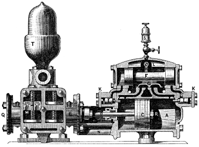
Fig. 102.—Steam-Pump.
A vastly simpler form of pumping-engine without fly-wheel is the now common “direct-acting steam-pump.” This engine is generally made use of in feeding steam-boilers, as a forcing and fire pump, and wherever the amount of water to be moved is not large, and where the pressure is comparatively great. The steam-cylinder, A R, and feed-pump, B Q (Fig. 102), are in line, and the two pistons have usually one rod, D, in common. The two cylinders are connected by a strong frame, N, and two standards fitted with lugs carry the whole, and serve as a means of bolting the pump to the floor or to its foundation.
The method of working the steam-valve of the modern steam-pump is ingenious and peculiar. As shown, the pistons are moving toward the left; when they reach the end of their stroke, the face of the piston strikes a pin or other contrivance, and thus moves a small auxiliary valve, I, which opens a port, E, and causes steam to be admitted behind a piston, or permits steam to be exhausted, as in the figure, from before the auxiliary piston, F, and the pressure within the main steam-chest then forces that piston over, moving the main steam-valve, G, to which it is attached, admitting steam to the left-hand side of the main piston, and exhausting on the right-hand side, A. Thus the motion of the engine operates its own valves in such a manner that it is never liable to stop working at the end of the stroke, notwithstanding the absence of the crank and fly-wheel, or of independent mechanism, like the cataract of the Cornish engine. There is a very considerable variety of pumps of this class, all differing in detail, but all presenting the distinguishing feature of auxiliary valve and piston, and a connection by which it and the main engine each works the valve of the other combination.
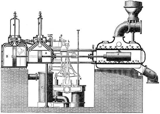
Fig. 103.—The Worthington Pumping-Engine, 1876. Section.
In some cases these pumps are made of considerable size, and are applied to the elevation of water in situations to which the Cornish engine was formerly considered exclusively applicable. The accompanying figure illustrates such a pumping-engine, as built for supplying cities with water. This is a “compound” direct-acting pumping-engine. The cylinders, A B, are placed in line, working one pump, F, and operating their own air-pumps, D D, by a bell-crank lever, L H, connected to the pump-buckets by links, I K. Steam exhausted from the small cylinder, A, is further expanded in the large cylinder, B, and thence goes to the condenser, C. The valves, N M, are moved by the valve-gear, L, which is actuated by the piston-rod of a similar pair of cylinders placed by the side of the first. These valves are balanced, and the balance-plates, R Q, are suspended from the rods, O P, which allow them to move with the valves. By connecting the valves of each engine with the piston-rod of the other, it is seen that the two engines must work alternately, the one making a stroke while the other is still, and then itself stopping a moment while the latter makes its stroke.
Water enters the pump through the induction-pipe, E, passes into the pump-barrel through the valves, V V, and issues through the eduction-valves, T T, and goes on to the “mains” by the pipe, G, above which is seen an air-chamber, which assists to preserve a uniform pressure on that side the pump. This engine works very smoothly and quietly, is cheap and durable, and has done excellent duty.
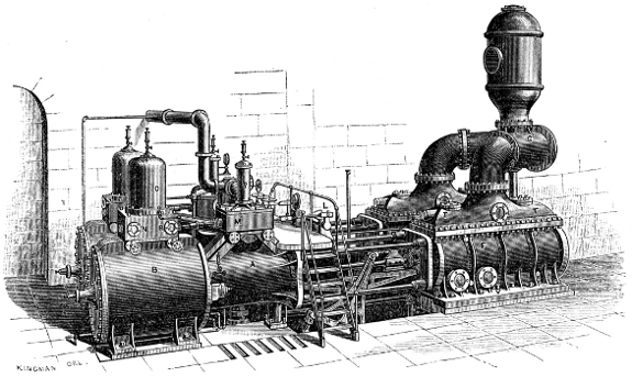
Fig. 104.—The Worthington Pumping-Engine.
Large scale image (362 kB).
Beam pumping-engines are now almost invariably built with crank and fly-wheel, and very frequently are compound engines. The accompanying illustration represents an engine of the latter form.
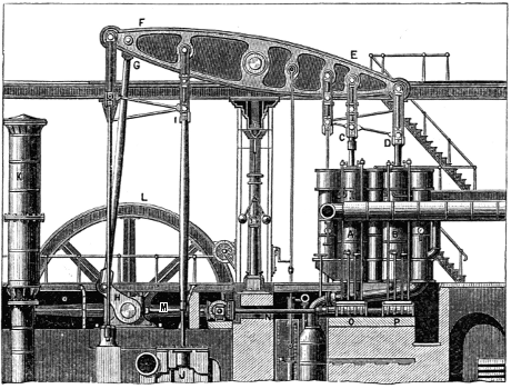
Fig. 105.—Double-Cylinder Pumping-Engine, 1878.
A and B are the two steam-cylinders, connected by links and parallel motion, C D, to the great cast-iron beam, E F. At the opposite end of the beam, the connecting-rod, G, turns a crank, H, and fly-wheel, L M, which regulates the motion of the engine and controls the length of stroke, averting all danger of accident occurring in consequence of the piston striking either cylinder-head. The beam is carried on handsomely-shaped iron columns, which, with cylinders, pump, and fly-wheel, are supported by a substantial stone foundation. The pump-rod, I, works a double-acting pump, J, and the resistance to the issuing water is rendered uniform by an air-chamber, K, within which the water rises and falls when pressures tend to vary greatly. A revolving shaft, N, driven from the fly-wheel shaft, carries cams, O P, which move the lifting-rods seen directly over them and the valves which they actuate. Between the steam-cylinders and the columns which carry the beams is a well, in which are placed the condenser and air-pump. Steam is carried at 60 or 80 pounds pressure, and expanded from 6 to 10 times.
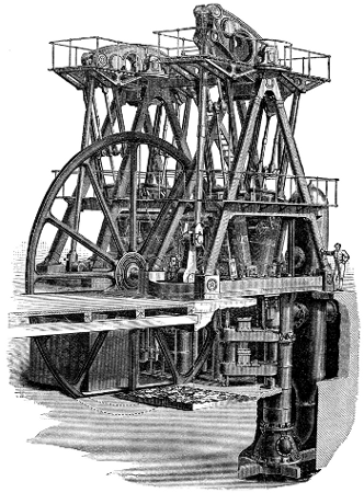
Fig. 106.—The Lawrence Water-Works Engine.
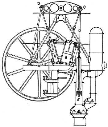
Fig. 107.—The Leavitt Pumping-Engine.
A later form of double-cylinder beam pumping-engine is that invented and designed by E. D. Leavitt, Jr., for the Lawrence Water-Works, and shown in Figs. 106 and 107. The two cylinders are placed one on each side the centre of the beam, and are so inclined that they may be coupled to opposite ends of it, while their lower ends are placed close together. At their upper ends a valve is placed at each end of the connecting steam-pipe. At their lower ends a single valve serves as exhaust-valve to the high-pressure and as steam-valve to the low-pressure cylinder. The pistons move in opposite directions, and steam is exhausted from the high-pressure cylinder directly into the nearer end of the low-pressure cylinder. The pump, of the “Thames-Ditton” or “bucket-and-plunger” variety, takes a full supply of water on the down-stroke, and discharges half when rising and half when descending again. The duty of this engine is reported by a board of engineers as 103,923,215 foot-pounds for every 100 pounds of coal burned. The duty of a moderately good engine is usually considered to be from 60 to 70 millions. This engine has steam-cylinders of 171∕2 and 36 inches diameter respectively, with a stroke of 7 feet. The pump had a capacity of about 195 gallons, and delivered 96 per cent. Steam was carried at a pressure of 75 pounds above the atmosphere, and was expanded about 10 times. Plain horizontal tubular boilers were used, evaporating 8.58 pounds of water from 98° Fahr. per pound of coal.
Steam-boilers.—The steam supplied to the forms of stationary engine which have been described is generated in steam-boilers of exceedingly varied forms. The type used is determined by the extent to which their cost is increased in the endeavor to economize fuel by the pressure of steam carried, by the greater or less necessity of providing against risk of explosion, by the character of the feed-water to be used, by the facilities which may exist for keeping in good repair, and even by the character of the men in whose hands the apparatus is likely to be placed.
As has been seen, the changes which have marked the growth and development of the steam-engine have been accompanied by equally marked changes in the forms of the steam-boiler. At first, the same vessel served the distinct purposes of steam-generator and steam-engine. Later, it became separated from the engine, and was then specially fitted to perform its own peculiar functions; and its form went through a series of modifications under the action of the causes already stated.
When steam began to be usefully applied, and considerable pressures became necessary, the forms given to boilers were approximately spherical, ellipsoidal, or cylindrical. Thus the boilers of De Caus (1615) and of the Marquis of Worcester (1663) were spherical and cylindrical; those of Savery (1698) were ellipsoidal and cylindrical. After the invention of the steam-engine of Newcomen, the pressures adopted were again very low, and steam-boilers were given irregular forms until, at the beginning of the present century, they were again of necessity given stronger shapes. The material was at first frequently copper; it is now usually wrought-iron, and sometimes steel.
The present forms of steam-boilers may be classified as plain, flue, and tubular boilers. The plain cylindrical or common cylinder boiler is the only representative of the first class in common use. It is perfectly cylindrical, with heads either flat or hemispherical. There is usually attached to the boiler a “steam-drum” (a small cylindrical vessel), from which the steam is taken by the steam-pipe. This enlargement of the steam-space permits the mist, held in suspension by the steam when it first rises from the surface of the water, to separate more or less completely before the steam is taken from the boiler.
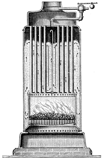
Fig. 108.—Babcock & Wilcox’s Vertical Boiler.
Flue-boilers are frequently cylindrical, and contain one or more cylindrical flues, which pass through from end to end, beneath the water-line, conducting the furnace-gases, and affording a greater area of heating-surface than can be obtained in the plain boiler. They are usually from 30 to 48 inches in diameter, and one foot or less in length for each inch of diameter. Some are, however, made 100 feet and more in length. The boiler is made of iron 1∕4 to 3∕8 of an inch in thickness, with hemispherical or carefully stayed flat heads, and without flues. The whole is placed in a brickwork setting. These boilers are used where fuel is inexpensive, where the cost of repairing would be great, or where the feed-water is impure. A cylindrical boiler, having one flue traversing it longitudinally, is called a Cornish boiler, as it is generally supposed to have been first used in Cornwall. It was probably first invented by Oliver Evans in the United States, previous to 1786, at which time he had it in use. The flue has usually a diameter 0.5 or 0.6 the diameter of the boiler. A boiler containing two longitudinal flues is called the Lancashire boiler. This form was also introduced by Oliver Evans. The flues have one-third the diameter of the boiler. Several flues of smaller diameter are often used, and when a still greater proportional area of heating-surface is required, tubes of from 11∕4 inch to 4 or 5 inches in diameter are substituted for flues. The flues are usually constructed by riveting sheets together, as in making the shell or outer portion. They are sometimes welded by British manufacturers, but rarely if ever in the United States. Tubes are always “lap-welded” in the process of rolling them. Small tubes were first used in the United States, about 1785. In portable, locomotive, and marine steam-boilers, the fire must be built within the boiler itself, instead of (as in the above described stationary boilers) in a furnace of brickwork exterior to the boiler. The flame and gases from the furnace or fire-box in these kinds of boiler are never led through brick passages en route to the chimney, as often in the preceding case, but are invariably conducted through flues or tubes, or both, to the smoke-stack. These boilers are also sometimes used as stationary boilers. Fig. 108 represents such a steam-boiler in section, as it is usually exhibited in working drawings. Provision is made to secure a good circulation of water in these boilers by means of the “baffle-plates,” seen in the sketch, which compel the water to flow as indicated by the arrows. The tubes are frequently made of brass or of copper, to secure rapid transmission of heat to the water, and thus to permit the use of a smaller area of heating-surface and a smaller boiler. The steam-space is made as large as possible, to secure immunity from “priming” or the “entrainment” of water with the steam. This type of steam-boiler, invented by Nathan Read, of Salem, Mass., in 1791, and patented in April of that year, was the earliest of the tubular boilers. In the locomotive boiler (Fig. 109), as in the preceding, the characteristics are a fire-box at one end of the shell and a set of tubes through which the gases pass directly to the smoke-stack. Strength, compactness, great steaming capacity, fair economy, moderate cost, and convenience of combination with the running parts, are secured by the adoption of this form. It is frequently used also for portable and stationary engines. It was invented in France by M. Seguin, and in England by Booth, and used by George Stephenson at about the same time—1828 or 1829.
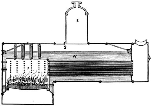
Fig. 109.—Stationary “Locomotive” Boiler.
Since the efficiency of a steam-boiler depends upon the extent of effective heating-surface per unit of weight of fuel burned in any given time—or, ordinarily, upon the ratio of the areas of heating and grate surface—peculiar expedients are sometimes adopted, having for their object the increase of heating-surface, without change of form of boiler and without proportionate increase of cost.
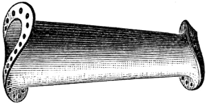
Fig. 110.
One of these methods is that of the use of Galloway conical tubes (Fig. 110). These are very largely used in Great Britain, but are seldom if ever seen in the United States. The Cornish boiler, to which they are usually applied, consists of a large cylindrical shell, 6 feet or more in diameter, containing one tube of about one-half as great dimensions, or sometimes two of one-third the diameter of the shell each. Such boilers have a very small ratio of heating to grate surface, and their large tubes are peculiarly liable to collapse. To remove these objections, the Messrs. Galloway introduced stay-tubes into the flues, which tubes are conical in form, and are set in either a vertical or an inclined position, the larger end uppermost. The area of heating-surface is thus greatly increased, and, at the same time, the liability to collapse is reduced. The same results are obtained by another device of Galloway, which is sometimes combined with that just described in the same boiler. Several sheets in the flue have “pockets” worked into them, which pockets project into the flue-passage.
Another device is that of an American engineer, Miller, who surrounds the furnace of cylindrical and other boilers with water-tubes. The “fuel-economizers” of Greene and others consist of similar collections of tubes set in the flues, between the boiler and the chimney.
“Sectional” boilers are gradually coming into use with high pressures, on account of their greater safety against disastrous explosions. The earliest practicable example of a boiler of this class was probably that of Colonel John Stevens, of Hoboken, N. J. Dr. Alban, who, forty years later, attempted to bring this type into general use, and constructed a number of such boilers, did not succeed. Their introduction, like that of all radical changes in engineering, has been but slow, and it has been only recently that their manufacture has become an important branch of industry.
A committee of the American Institute, of which the author was chairman, in 1871, examined several boilers of this and the ordinary type, and tested them very carefully. They reported that they felt “confident that the introduction of this class of steam-boilers will do much toward the removal of the cause of that universal feeling of distrust which renders the presence of a steam-boiler so objectionable in every locality. The difficulties in thoroughly inspecting these boilers, in regulating their action, and other faults of the class, are gradually being overcome, and the committee look forward with confidence to the time when their use will become general, to the exclusion of older and more dangerous forms of steam-boilers.”
The economical performance of these boilers with a similar ratio of heating to grate surface is equal to that of other kinds. In fact, they are usually given a somewhat higher ratio, and their economy of fuel frequently exceeds that of the other types. Their principal defect is their small capacity for steam and water, which makes it extremely difficult to obtain steady steam-pressure. Where they are employed, the feed and draught should be, if possible, controlled by automatic attachments, and the feed-water heated to the highest attainable temperature. Their satisfactory working depends, more than in other cases, on the ability of the fireman, and can only be secured by the exercise of both care and skill.
Many forms of these boilers have been devised. Walter Hancock constructed boilers for his steam-carriage of flat plates connected by stay-bolts, several such sections composing the boiler; and about the same time (1828) Sir Goldsworthy Gurney constructed for a similar purpose boilers consisting of a steam and a water reservoir, placed one above the other, and connected by triangularly-bent water-tubes exposed to the heat of the furnace-gases. Jacob Perkins made many experiments looking to the employment of very high steam-pressures, and in 1831 patented a boiler of this class, in which the heating-surfaces nearest the fire were composed of iron tubes, which tubes also served as grate-bars. The steam and water space was principally comprised within a comparatively large chamber, of which the walls were secured by closely distributed stay-bolts. For extremely high pressures, boilers composed only of tubes were used. Dr. Ernst Alban described the boiler already referred to, and its construction and operation, and stated that he had experimented with pressures as high as 1,000 pounds to the square inch.
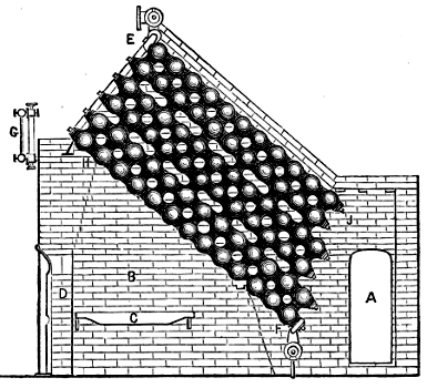
Fig. 111.—Harrison’s Sectional Boiler.
The Harrison steam-boiler, which has been many years in use in the United States, consists of several sections, each of which is made up of hollow globes of cast-iron, communicating with each other by necks cast upon the spheres, and fitted together with faced joints. Long bolts, extending from end to end of each row, bind the spheres together. (See Fig. 111.)
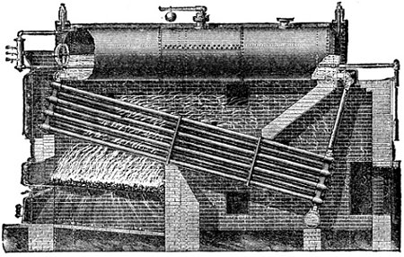
Fig. 112.—Babcock and Wilcox’s Sectional Boiler.
An example of another modern type in extensive use is given in Fig. 112, a semi-sectional boiler, which consists of a series of inclined wrought-iron tubes, connected by T-heads, which form the vertical water-channels, at each end. The joints are faced by milling them, and then ground so perfectly tight that a pressure of 500 pounds to the square inch is insufficient to produce leakage. No packing is used. The fire is made under the front and higher end of the tubes, and the products of combustion pass up between the tubes into a combustion-chamber under the steam and water drum; hence they pass down between the tubes, then once more up through the space between the tubes, and off to the chimney. The steam is taken out at the top of the steam-drum near the back end of the boiler. The rapid circulation prevents to some extent the formation of deposits or incrustations upon the heating-surfaces, sweeping them away and depositing them in the mud-drum, whence they are blown out. Rapid circulation of water, as has been shown by Prof. Trowbridge, also assists in the extraction of the heat from the gases, by the presentation of fresh water continually, as well as by the prevention of incrustation.
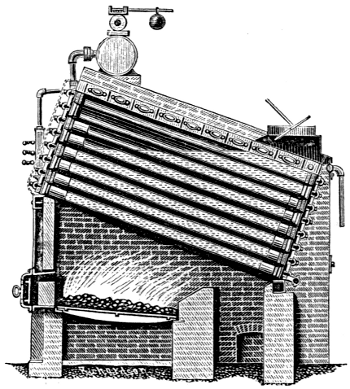
Fig. 113.—Root Sectional Boiler.
Attempts have been made to adapt sectional boilers to marine engines; but very little progress has yet been made in their introduction. The Root sectional boiler (Fig. 113), an American design, which is in extensive use in the United States and Europe, has also been experimentally placed in service on shipboard. Its heating-surface consists wholly of tubes, which are connected by a peculiarly formed series of caps; the joints are made tight with rubber “grummets.”
Section II.—Portable and Locomotive Engines.
Engines and boilers, when of small size, are now often combined in one structure which may be readily transported. Where they have a common base-plate simply, as in Fig. 114, they are called, usually, “semi-portable engines.” These little engines have some decided advantages. Being attached to one base, the combined engine and boiler is easily transported, occupies little space, and may very readily be mounted upon wheels, rendering it peculiarly well adapted for agricultural purposes.
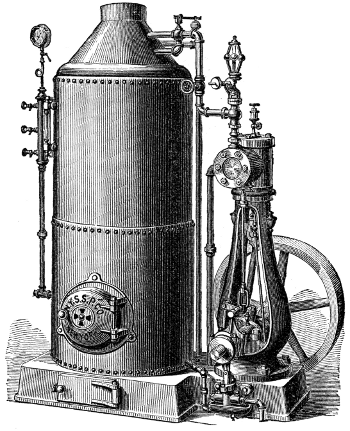
Fig. 114.—Semi-Portable Engine, 1878.
The example here shown differs in its design from those usually seen in the market. The engine is not fastened to or upon the boiler, and is therefore not affected by expansion, nor are the bearings overheated by conduction or by ascending heat from the boiler. The fly-wheel is at the base, which arrangement secures steadiness at the high speed which is a requisite for economy of fuel. The boilers are of the upright tubular style, with internal fire-box, and are intended to be worked at 150 pounds pressure per inch. They are fitted with a baffle-plate and circulating-pipe, to prevent priming, and also with a fusible plug, which will melt and prevent the crown-sheet of the boiler burning, if the water gets low.
Another illustration of this form of engine, as built in small sizes, is seen below. The peculiarity of this engine is, that the cylinder is placed in the top of the boiler, which is upright. By this arrangement the engine is constantly drawing from the boiler the hottest and driest steam, and there is thus no liability of serious loss by condensation, which is rapid, even in a short pipe, when the engine is separate from the boiler.
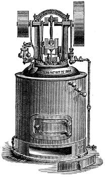
Fig. 115.—Semi-Portable Engine, 1878.
The engine illustrated is rated at 10 horse-power, and makers are always expected to guarantee their machines to work up to the rated power. The cylinder is 7 by 7 inches, and the main shaft is directly over it. On this shaft are three eccentrics, one working the pump, one moving the valves, and the third one operating the cut-off. The driving-pulley is 20 inches in diameter, and the balance-wheel 30 inches. The boiler has 15 11∕4-inch flues. It is furnished with a heater in its lower portion. The boiler of this engine is tested up to 200 pounds, and is calculated to carry 100 pounds working pressure, though that is not necessary to develop the full power of the engine. The compactness of the whole machine is exceptional. It can be set up in a space 5 feet square and 8 feet high. The weight of the 10 horse-power engine is 1,540 pounds, and of the whole machine 4,890 pounds, boxed for shipment. Every part of the mechanism usually fits and works with the exactness of a gun-lock, as each piece is carefully made to gauge.
Portable engines are those which are especially intended to be moved conveniently from place to place. The engine is usually attached to the boiler, and the feed-pump is generally attached to the engine. The whole machine is carried on wheels, and is moved from one place to another, usually by horses, but sometimes by its own engine, which is coupled by an engaging and disengaging apparatus to the rear-wheels. English builders have usually excelled in the construction of this class of steam-engine, although it is probable that the best American engines are fully equal to them in design, material, and construction.
The later work of the best-known English builders has given economical results that have surprised engineers. The annual “shows” of the Royal Agricultural Society have elicited good evidence of skill in management as well as of excellence of design and construction. Some little portable engines have exhibited an economical efficiency superior to that of the largest marine engines of any but the compound type, and even closely competing with that form. The causes of this remarkable economy are readily learned by an inspection of these engines, and by observation of the method of managing them at the test-trial. The engines are usually very carefully designed. The cylinders are nicely proportioned to their work, and their pistons travel at high speed. Their valve-gear consists usually of a plain slide-valve, supplemented by a separate expansion-slide, driven by an independent eccentric, and capable of considerable variation in the point of cut-off. This form of expansion-gear is very effective—almost as much so as a drop cut-off—at the usual grade of expansion, which is not far from four times. The governor is usually attached to a throttle-valve in the steam-pipe, an arrangement which is not the best possible under variable loads, but which produces no serious loss of efficiency when the engine is driven, as at competitive trials, under the very uniform load of a Prony strap-brake and at very nearly the maximum capacity of the machine. The most successful engines have had steam-jacketed cylinders—always an essential to maximum economy—with high steam and a considerable expansion. The boilers are strongly made, and are, as are also all other heated surfaces, carefully clothed with non-conducting material, and well lagged over all. The details are carefully proportioned, the rods and frames are strong and well secured together, and the bearings have large rubbing-surfaces. The connecting-rods are long and easy-working, and every part is capable of doing its work without straining and with the least friction.
In handling the engines at the competitive trial, most experienced and skillful drivers are selected. The difference between the performances of the same engine in different hands has been found to amount to from 10 to 15 per cent., even where the competitors were both considered exceptionally skillful men. In manipulating the engine, the fires are attended to with the utmost care; coal is thrown upon them at regular and frequent intervals, and a uniform depth of fuel and a perfectly clean fire are secured. The sides and corners of the fire are looked after with especial care. The fire-doors are kept open the least possible time; not a square inch of grate-surface is left unutilized, and every pound of coal gives out its maximum of calorific power, and in precisely the place where it is needed. Feed-water is supplied as nearly as possible continuously, and with the utmost regularity. In some cases the engine-driver stands by his engine constantly, feeding the fire with coal in handfuls, and supplying the water to the heater by hand by means of a cup. Heaters are invariably used in such cases. The exhaust is contracted no more than is absolutely necessary for draught. The brake is watched carefully, lest irregularity of lubrication should cause oscillation of speed with the changing resistance. The load is made the maximum which the engine is designed to drive with economy. Thus all conditions are made as favorable as possible to economy, and they are preserved as invariable as the utmost care on the part of the attendant can make them.
These trials are usually of only three or five hours’ duration, and thus terminate before it becomes necessary to clean fires. The following are results obtained at the trial of engines which took place in July, 1870, at the Oxford Agricultural Fair:
MAKER’S NAME AND RESIDENCE Cylinders. Stroke. Horse-Power. Point of cut off. Revolutions per minute. Pounds coal per horse-power per hour.
Number. Diameter. Nominal. Dynamo- metric.
Inches. In.
Clayton, Shuttleworth & Co., Lincoln 1 7 12 4 4.42 ..... 121.6 5 3.73
Brown & May, Devizes 1 7 3∕16 12 4 4.19 11.48 125.6 5 4.44
Reading Iron-Works Company, Reading 1 5 3∕4 14 4 4.16 ..... 145.7 4.65
These were horizontal engines, attached to locomotive boilers.
At a similar exhibition held at Bury, in 1867, considerably better results even than these were reported, as below, from engines of similar size and styles:
MAKER’S NAME AND RESIDENCE Cylinders. Stroke. Horse-Power. Point of cut off. Revolutions per minute. Pounds coal per horse-power per hour.
Number. Diameter. Nominal. Dynamo- metric.
Inches. In.
Clayton, Shuttleworth & Co., Lincoln. 1 10 20 10 11.00 3.1 0 71.5 4.13
Reading Iron-Works Company, Reading. 1 8 5∕8 20 10 10.43 1.4 109.4 4.22
With all these engines steam-jackets were used; the feed-water was highly and uniformly heated by exhaust-steam; the coal was selected, finely broken, and thrown on the fire with the greatest care; the velocity of the engines, the steam-pressure, and the amount of feed-water, were very carefully regulated, and all bearings were run quite loose; the engine-drivers were usually expert “jockeys.”
The next illustration represents the portable steam-engine as built by one of the oldest and most experienced manufacturers of such engines in the United States.
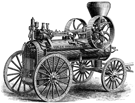
Fig. 116.—The Portable Steam-Engine, 1878.
In the boilers of these engines the heating-surface is given less extent than in the stationary engine-boiler, but much greater than in the locomotive, and varies from 10 to 20 square feet per horse-power. The boilers are made very strong, to enable them to withstand the strains due to the attached engine, which are estimated as equivalent to from one-tenth to one-fifth that due to the steam-pressure. The boiler is sometimes given even double the strength usual with stationary boilers of similar capacity. The engine is mounted, in this example, directly over the boiler, and all parts are in sight and readily accessible to the engineer.
One of these engines, of 20 horse-power, has a steam-cylinder 10 inches in diameter and 18 inches stroke of piston, making 125 revolutions per minute, and has 9 square feet of grate-surface and 288 feet of heating-surface. It weighs about 41∕2 tons. Steam is carried at 125 pounds.
In the class of engines just described, the draught is obtained by the blast of the exhaust-steam which is led into the chimney. Such engines are now sold at from $120 to $150 per horse-power, according to size and quality, the smaller engines costing most. The usual consumption of fuel is from 4 to 6 pounds per hour and per horse-power, burning from 15 to 20 pounds on each square foot of grate, and each pound evaporating about 8 pounds of water. A usual weight is, for the larger sizes, 500 pounds per horse-power.
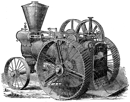
Fig. 117.—The Thrashers’ Road-Engine, 1878.
These engines are sometimes arranged to propel themselves, as in the Mills “Thrashers’” road-engine or locomotive, of which the accompanying engraving is a good representation. This engine is proportioned for hauling a tank containing 10 barrels, or more, of water and a grain-separator over all ordinary roads, and to drive a thrashing-machine or saw-mill, developing 20 or 25 horse-power. This example of the road-engine has a boiler built to work at 250 pounds of steam; the engine is designed for a maximum power of 30 horses.
This engine has a balanced valve and automatic cut-off, and is fitted with a reversing-gear for use on the road. The driving-wheels are of wrought-iron, 56 inches diameter and 8 inches wide, with cast-iron driving-arms. Both wheels are drivers on curves as well as on straight lines. The engine is guided and fired by one man, and the total weight is so small that it will pass safely over any good country bridge. A brake is attached, to insure safety when going down-hill. Although designed to move at a speed of about three miles per hour, the velocity of the piston may be increased so that four miles per hour may be accomplished when necessary.
This is an excellent example of this kind of engine as constructed at the present time. The strongly-built boiler, with its heater, the jacketed cylinder, and light, strong frame of the engine, the steel running-gear, the carefully-covered surfaces of cylinder and boiler, and excellent proportions of details, are illustrations of good modern engineering, and are in curious contrast with the first of the class, built a century earlier by Smeaton.
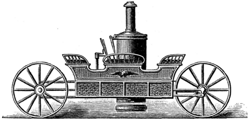
Fig. 118.—Fisher’s Steam-Carriage.
Steam-carriages for passengers are now rarely built. Fig. 118 represents that designed by Fisher about 1870 or earlier. It was only worked experimentally.
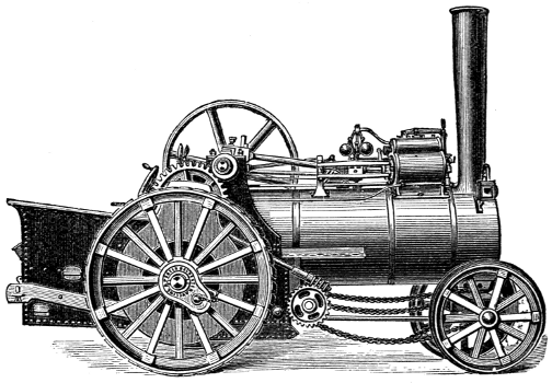
Fig. 119.—Road and Farm Locomotive.
The above is an engraving of a road and farm locomotive as built by one of the most successful among several British firms engaged in this work.
The capacity of these engines has been determined by experiment by the author in the United States, and abroad by several distinguished engineers.
The author made a trial of one of these engines at South Orange, N. J., to determine its power, speed, and convenience of working and manœuvring. The following were the principal dimensions:
Weight of engine, complete, 5 tons 4 cwt. 11,648 pounds.
Steam-cylinder—diameter 7 3∕4 inches.
Stroke of piston 10 inches.
Revolution of crank to one of driving-wheels 17
Driving-wheels— diameter 60 inches.
„ breadth of tire 10 inches.
„ weight, each 450 pounds.
Boiler— length over all 8 feet.
„ diameter of shell 30 feet.
„ thickness of shell 7∕16 inch.
„ fire-box sheets, outside, thickness 1∕2 inch.
Load on driving-wheels, 4 tons 10 cwt. 10,080 pounds.
The boiler was of the ordinary locomotive type, and the engine was mounted upon it, as is usual with portable engines.
The steam-cylinder was steam-jacketed, in accordance with the most advanced practice here and abroad. The crank-shaft and other wrought-iron parts subjected to heavy strains were strong and plainly finished. The gearing was of malleableized cast-iron, and all bearings, from crank-shaft to driving-wheel, on each side, were carried by a single sheet of half-inch plate, which also formed the sides of the fire-box exterior.
The following is a summary of the conclusions deduced by the author from the trial, and published in the Journal of the Franklin Institute: A traction-engine may be so constructed as to be easily and rapidly manœuvred on the common road; and an engine weighing over 5 tons may be turned continuously without difficulty on a circle of 18 feet radius, or even on a road but little wider than the length of the engine. A locomotive of 5 tons 4 hundredweight has been constructed, capable of drawing on a good road 23,000 pounds up a grade of 533 feet to the mile, at the rate of four miles an hour; and one might be constructed to draw more than 63,000 pounds up a grade of 225 feet to the mile, at the rate of two miles an hour.
It was further shown that the coefficient of traction with heavily-laden wagons on a good macadamized road is not far from .04; the traction-power of this engine is equal to that of 20 horses; the weight, exclusive of the weight of the engine, that could be drawn on a level road, was 163,452 pounds; and the amount of fuel required is estimated at 500 pounds a day. The advantages claimed for the traction-engine over horse-power are: no necessity for a limitation of working-hours; a difference in first cost in favor of steam; and in heavy work on a common road the expense by steam is less than 25 per cent. of the average cost of horse-power, a traction-engine capable of doing the work of 25 horses being worked at as little expense as 6 or 8 horses. The cost of hauling heavy loads has been estimated at 7 cents per ton per mile.
Such engines are gradually becoming useful in steam-ploughing. Two systems are adopted. In the one the engine is stationary, and hauls a “gang” of ploughs by means of a windlass and wire rope; in the other the engine traverses a field, drawing behind it a plough or a gang of ploughs. The latter method has been proposed for breaking up prairie-land.
Thus, thirty years after the defeat of the intelligent, courageous, and persistent Hancock and his coworkers in the scheme of applying the steam-engine usefully on the common road, we find strong indications that, in a new form, the problem has been again attacked, and at least partially solved.
One of the most important of the prerequisites to ultimate success in the substitution of steam for animal power on the highway is that our roads shall be well made. As the greatest care and judgment are exercised, and an immense outlay of capital is considered justifiable, in securing easy grades and a smooth track on our railroad routes, we may readily believe that similar precaution and outlay will be found advisable in adapting the common road to the road-locomotive. It would seem to the engineer that the natural obstacles generally supposed to stand in the way have, after all, no real existence. The principal inconvenience that may be anticipated will probably arise from the carelessness or avarice of proprietors, which may sometimes cause them to appoint ignorant and inefficient engine-drivers, giving them charge of what are always excellent servants, but terrible masters. Nevertheless, as the transportation of passengers on railroads is found to be attended with less liability to loss of life or injury of person than their carriage by stage-coach, it will be found, very probably, that the general use of steam in transporting freight on common roads may be attended with less risk to life or property than to-day attends the use of horse-power.
The Steam Fire-Engine is still another form of portable engine. It is also one of the latest of all applications of steam-power. The steam fire-engine is peculiarly an American production. Although previously attempted, their permanently successful introduction has only occurred within the last fifteen years.
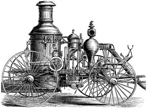
Fig. 120.—The Latta Steam Fire-Engine.
As early as 1830, Braithwaite and Ericsson, of London, England, built an engine with steam and pump cylinders of 7 and 61∕2 inches diameter, respectively, with 16 inches stroke of piston. This machine weighed 21∕2 tons, and is said to have thrown 150 gallons of water per minute to a height of between 80 and 100 feet. It was ready for work in about 20 minutes after lighting the fire. Braithwaite afterward supplied a more powerful engine to the King of Prussia, in 1832. The first attempt made in the United States to construct a steam fire-engine was probably that of Hodge, who built one in New York in 1841. It was a strong and very effective machine, but was far too heavy for rapid transportation. The late J. K. Fisher, who throughout his life persistently urged the use of steam-carriages and traction-engines, designing and building several, also planned a steam fire-engine. Two were built from his design by the Novelty Works, New York, about 1860, for Messrs. Lee & Larned. They were “self-propellers,” and one of them, built for the city of Philadelphia, was sent to that city over the highway, driven by its own engines. The other was built for and used by the New York Fire Department, and did good service for several years. These engines were heavy, but very powerful, and were found to move at good speed under steam and to manœuvre well. The Messrs. Latta, of Cincinnati, soon after succeeded in constructing comparatively light and very effective engines, and the fire department of that city was the first to adopt steam fire-engines definitely as their principal reliance. This change has now become general.
The steam fire-engine has now entirely displaced the old hand-engine in all large cities. It does its work at a fraction of the cost of the latter. It can force its water to a height of 225 feet, and to a distance of more than 300 feet horizontally, while the hand-engine can seldom throw it one-third these distances; and the “steamer” may be relied upon to work at full power many hours if necessary, while the men at the hand-engine soon become fatigued, and require frequent relief. The city of New York has 40 steam fire-engines. One engine to every 10,000 inhabitants is a proper proportion.
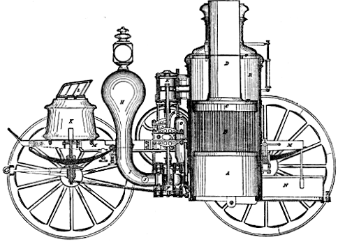
Fig. 121.—The Amoskeag Engine. Section.
In the standard steam fire-engine (Fig. 120) reciprocating engines and pumps are adopted, as seen in section in Fig. 121, in which A is the furnace, and B the set of closely-set vertical fire-tubes in the boiler. C is the combustion-chamber, D the smoke-pipe, and R the steam-space. E is the steam-cylinder, and F the pump, which is seen to be double-acting. There are two pairs of engines and pumps, working on cranks, set at right angles, and turning a balance-wheel seen behind them. G is the feed-pump which supplies water to the boiler, H the air-chamber which equalizes the water-pressure, which reaches it through the pipe, I J. K is the feed-water tank, under the driver’s seat, L, which, with the engines and boiler, are carried on the frame, M M. The fireman stands on the platform, N. When it is necessary to move the machine, an endless chain connects the crank-shaft with the rear-wheels, and the engine, with pumps shut off, is thus made to drive the wheels at any desired speed.
A self-propelling engine by the Amoskeag Company had the following dimensions and performance: Weight, 4 tons; speed, 8 miles per hour; steam-pressure, 75 pounds per square inch; height of stream from 11∕4-inch nozzle, 225 feet; 13∕4-inch nozzle, 150 feet; distance horizontally, 11∕4-inch nozzle, 300 feet; 13∕4-inch, 250 feet—a performance which contrasts wonderfully with that of the hand-worked fire-engine which these engines have now superseded.
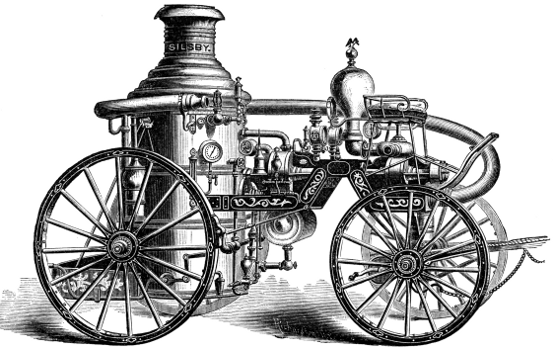
Fig. 122.—The Silsby Rotary Steam Fire-Engine.
It has recently become common to construct the steam fire-engine with rotary engine and pump (Fig. 122). The superiority of a rotary motion for a steam-engine is apparently so evident that many attempts have been made to overcome the practical difficulties to which it is subject. One of these difficulties, and the principal one, has been the packing of the part which performs the office of the piston in the straight cylinder. Robert Stephenson once expressed the opinion that a rotary engine would never be made to work successfully, on account of this difficulty of packing. The most palpable of the advantages of the rotary engine are the reduction in the size of the engine, claimed to result from the great velocity of the piston; the avoidance of great accidental strains, especially noticed in propelling ships; and a great saving of the power which is asserted to be expended in the reciprocating engine in overcoming the inertia while changing the direction of the motions. These advantages adapt the rotary engine, in an especial manner, to the driving of a locomotive or steam fire-engine.
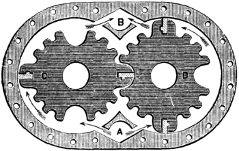
Fig. 123.—Rotary Steam-Engine.
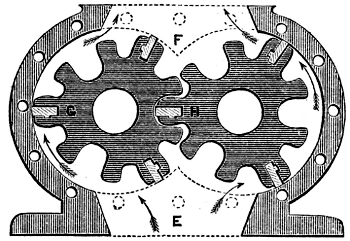
Fig. 124.—Rotary Pump.
In the Holly rotary engine, seen in Fig. 123, eccentrics and sliding-cams, which are frequently used in rotary engines, and which are objectionable on account of their great friction, are avoided. Corrugated pistons, or irregular cams, C D, are adopted, forming chambers within the cases. In the engine the steam enters at A, at the bottom of the case, and presses the cams apart. The only packing used is in the ends of the long metal cogs, which are ground to fit the case and are kept out by the momentum of the cams, assisted by a slight spring back of the packing-pieces. The friction on the pump (Fig. 124) is said to be less than in the engine. This is the reason given in support of the claim that the rotary engine forces water to a given distance with from one-fourth to one-third the steam-pressure necessary to drive all reciprocating engines. The smaller amount of power necessary to do the work, the less strain and consequent wear and tear upon the whole machine, are said to make it more durable and reliable. The pump being chambered, its liability to injury by the use of dirty or gritty water is lessened, and it is stated that it will last for years, pumping gritty water that would soon cut out a piston-pump. The pump used with this engine is, as shown in the above illustration, somewhat similar to the rotary engine driving it. Each of the revolving pistons has three long teeth bearing against the cylinder, and packed, to prevent leakage, like the engine-cams. They are carried on steel shafts coupled to the engine-shafts. The water enters at E and is discharged at F, and the passages are purposely made large in order that sand, chips, and dirt, which may enter with the water, may pass through.
The rotary engine is gradually coming into use for various special purposes, where small power is called for, and where economy of fuel is not important; but it has never yet competed, and may perhaps never in the future compete, with the reciprocating-piston engine where large engines are required, or where even moderate economy of fuel is essential. This form of engine has assumed so little importance, in fact, in the application of the steam-engine, that comparatively little is known of its history. Watt invented a rotary engine, and Yule many years afterward (1836) constructed such engines at Glasgow. Lamb patented another in 1842, Behrens still another in 1847. Napier, Hall, Massey, Holly, La France, and others, have built engines of this class in later times. Nearly all consist either of cams rotating in gear, as in those above sketched, or of a piston set radially in a cylinder of small diameter, which turns on its axis within a much larger cylinder set eccentrically, the piston, as the former turns, sliding in and out of the smaller cylinder as its outer edge slides in contact with the inner surface of the larger. In some forms of rotary engine, a piston revolves on a central shaft, and a sliding abutment in the external cylinder serves to separate the steam from the exhaust side and to confine the steam expanding while doing work. Nearly all of these combinations are also used as pumps.
Fire-engines, made by the best-known American builders of engines, with reciprocating engines and pumps, such as are in general use in the United States, have become standard in general plan and arrangement of details. These are probably the best illustrations of extreme lightness, combined with strength of parts and working power, which have ever been produced in any branch of mechanical engineering. By using a small boiler crowded with heating-surface, very carefully proportioned and arranged, and with small water-spaces; by adopting steel for running-gear and working parts wherever possible; by working at high piston-speed and with high steam-pressure; by selecting fuel with extreme care—by all these expedients, the steam fire-engine has been brought, in this country, to a state of efficiency far superior to anything seen elsewhere. Steam is raised with wonderful promptness, even from cold water, and water is thrown from the nozzle at the end of long lines of hose to great distances. But this combination of lightness with power is only attained at the expense of a certain regularity of action which can only be secured by greater water and steam capacity in the boiler. The small quantity of water contained within the boiler makes it necessary to give constant attention to the feed, and the tendency, almost invariably observed, to serious foaming and priming not only compels unintermitted care while running, but even introduces an element of danger which is not to be despised, even though the machine be in charge of the most experienced and skillful attendants. Even the greatest care, directed by the utmost skill, would not avail to prevent frequent explosions, were it not for the fact that it rarely, if ever, happens that accidents to such boilers occur from low water, unless the boiler is actually completely emptied of water. In driving them at fires, they frequently foam so violently that it is utterly impossible to obtain any clew to the amount of water present, and the attendant usually keeps his feed-pump on and allows the foaming to go on. As long as water is passing into the boiler it is very unlikely that any portion will become overheated and that accident will occur. Such management appears very reckless, and yet accident from such a cause is exceedingly rare.
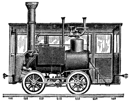
Fig. 125.—Tank-Engine, New York Elevated Railroad.
The changes which have been made in Locomotive-Construction during the past few years have also been in the direction of the refinement of the earlier designs, and have been accompanied by corresponding changes in all branches of railroad-work. The adjustment of parts to each other and proportioning them to their work, the modification of the minor details to suit changes of general dimensions, the improvement of workmanship, and the use of better material, have signalized this latest period. Special forms of engine have been devised for special kinds of work. Small, light tank-engines (Fig. 125), carrying their own fuel and water without “tenders,” are used for moving cars about terminal stations and for making up trains; powerful, heavy, slow-moving engines, of large boiler-capacity and with small wheels, are used on steep gradients and for hauling long trains laden with coal and heavy merchandise; and hardly less powerful but quite differently proportioned “express”-engines are used for passenger and mail service.
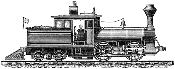
Fig. 126.—Forney’s Tank-Locomotive.
A peculiar form of engine (Fig. 126) has been designed by Forney, in which the whole weight of engine, tender, coal, and water, is carried by one frame and on one set of wheels, the permanent weight falling on the driving-wheels and the variable load on the truck. These engines have also a comparatively short wheel-base and high pulling-power. The lightest tank-engines of the first class mentioned weigh 8 or 10 tons; but engines much lighter than these, even, are built for mines, where they are sent into the galleries to bring out the coal-laden wagons. The heaviest engines of this class attain weights of 20 or 30 tons. The heaviest engine yet constructed in the United States is said to be one in use on the Philadelphia & Reading Railroad, having a weight of about 100,000 pounds, which is carried on 12 driving-wheels.
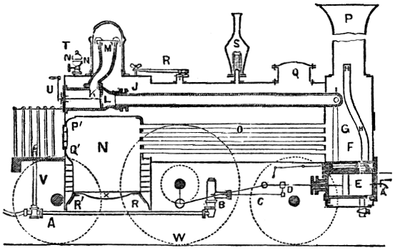
Fig. 127.—British Express Engine.
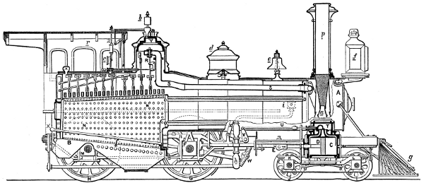
Fig. 128.—The Baldwin Locomotive. Section.
A locomotive has two steam-cylinders, either side by side within the frame, and immediately beneath the forward end of the boiler, or on each side and exterior to the frame. The engines are non-condensing, and of the simplest possible construction. The whole machine is carried upon strong but flexible steel springs. The steam-pressure is usually more than 100 pounds. The pulling-power is generally about one-fifth the weight under most favorable conditions, and becomes as low as one-tenth on wet rails. The fuel employed is wood in new countries, coke in bituminous coal districts, and anthracite coal in the eastern part of the United States. The general arrangement and the proportions of locomotives differ somewhat in different localities. In Fig. 127, a British express-engine, O is the boiler, N the fire-box, X the grate, G the smoke-box, and P the chimney. S is a spring and R a lever safety-valve, T is the whistle, L the throttle or regulator valve, E the steam-cylinder, and W the driving-wheel. The force-pump, B C, is driven from the cross-head, D. The frame is the base of the whole system, and all other parts are firmly secured to it. The boiler is made fast at one end, and provision is made for its expansion when heated. Adhesion is secured by throwing a proper proportion of the weight upon the driving-wheel, W. This is from about 6,000 pounds on standard freight-engines, having several pairs of drivers, to 10,000 pounds on passenger-engines, per axle. The peculiarities of the American type (Fig. 128) are the truck, I J, or bogie, supporting the forward part of the engine, the system of equalizers, or beams which distribute the weight of the machine equally over the several axles, and minor differences of detail. The cab or house, r, protecting the engine-driver and fireman, is an American device, which is gradually coming into use abroad also. The American locomotive is distinguished by its flexibility and ease of action upon even roughly-laid roads. In the sketch, which shows a standard American engine in section, A B is the boiler, C one of the steam-cylinders, D the piston, E the cross-head, connected to the crank-shaft, F, by the connecting-rod, G H the driving-wheels, I J the truck-wheels, carrying the truck, K L; N N is the fire-box, O O the tubes, of which but four are shown. The steam-pipe, R S, leads the steam to the valve-chest, T, in which is seen the valve, moved by the valve-gear, U V, and the link, W. The link is raised or depressed by a lever, X, moved from the cab. The safety-valve is seen at the top of the dome, at Y, and the spring-balance by which the load is adjusted is shown at Z. At a is the cone-shaped exhaust-pipe, by which a good draught is secured. The attachments b, c, d, e, f, g—whistle, steam-gauge, sand-box, bell, head-light, and “cow-catcher”—are nearly all peculiar, either in construction or location, to the American locomotive. The cost of passenger-locomotives of ordinary size is about $12,000; heavier engines sometimes cost $20,000. The locomotive is usually furnished with a tender, which carries its fuel and water. The standard passenger-engine on the Pennsylvania Railroad has four driving-wheels, 51∕2 feet diameter; steam-cylinders, 17 inches diameter and 2 feet stroke; grate-surface 151∕2 square feet, and heating-surface 1,058 square feet. It weighs 63,100 pounds, of which 39,000 pounds are on the drivers and 24,100 on the truck. The freight-engine has six driving-wheels, 545∕8 inches in diameter. The steam-cylinders are 18 inches in diameter, stroke 22 inches, grate-surface 14.8 square feet, heating-surface 1,096 feet. It weighs 68,500 pounds, of which 48,000 are on the drivers and 20,500 on the truck. The former takes a train of five cars up an average grade of 90 feet to the mile. The latter is attached to a train of 11 cars. On a grade of 50 feet to the mile, the former takes 7 and the latter 17 cars. Tank-engines for very heavy work, such as on grades of 320 feet to the mile, which are found on some of the mountain lines of road, are made with five pairs of driving-wheels, and with no truck. The steam-cylinders are 201∕8 inches in diameter, 2 feet stroke; grate-area, 153∕4 feet; heating-surface, 1,380 feet; weight with tank full, and full supply of wood, 112,000 pounds; average weight, 108,000 pounds. Such an engine has hauled 110 tons up this grade at the speed of 5 miles an hour, the steam-pressure being 145 pounds. The adhesion was about 23 per cent. of the weight.