Production of Electric Currents by Mechanical Means.
Reading edition
Magneto-electric Machines.
I have shown how the electric current is produced by the action of chemical or primary batteries, and how this current will flow through suitable conductors. Current produced by mechanical means. I shall now explain how mechanical power may be converted into electricity. It has been found that if a wire, preferably of copper, of which the ends are joined together, is moved past a magnet a current is induced in the wire, flowing in one direction while the wire is approaching the magnet, and in the opposite direction while it is receding from it. Alternating current. This is then not a continuous current like we obtained from the chemical battery, but an alternating one, and you will see later on how it can be made to produce similar effects. The oftener the wire passes the magnet the more electricity is generated, so that if we make a coil of the wire and move a large number of parts of wire past at one time, the effects on each part are accumulated; and if instead of having one magnet to pass before, we have several, the effects will be doubled or trebled, &c., in proportion to the number. If, again, the coil is moved at an increased speed past the magnets, the effects will be still further increased.
Fig. 2.
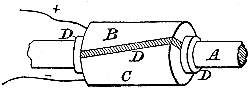
Magneto-electric machines. The knowledge of these facts led to the construction of the various magneto-electric machines, of which a familiar type is seen in those small ones used for medical purposes. They contain a large horse-shoe magnet, close to the end of which two bobbins of copper wire are made to revolve at a high speed, and all who have used these machines know that the more quickly they turn the handle the greater shock the person receives who is being operated upon. Shock produced by interruption of current. The current generated is really very feeble, the shock being produced by interrupting it at every half revolution by means of a small spring or other suitable mechanism. If the current is not so interrupted, it cannot be felt at all, which may be proved by lifting up the spring on the spindle of the ordinary kind. The current is an alternating one, and changes its direction throughout the circuit, however extended it may be, at every half revolution. The current must be commutated. If it is required to have a continuous current, use must be made of what is termed a commutator, and I shall endeavour to explain the manner in which it acts as simply as possible. Without going into any further details as to the construction of the bobbins, and their action at any particular moment, I shall content myself with saying that if the wire on the two bobbins is continuous, and the ends are connected, the current will flow one way during half a revolution, and the other way during the other half. Description of commutator. Now, in Fig. 2, on the spindle A on which the bobbins are fixed, is fitted a split collar formed of two halves B and C, to which are joined respectively the ends of the wires + and -. This collar is insulated from the spindle by a suitable insulating material, that is to say, a material which does not conduct electricity, such as wood, ivory, &c., and is represented in Fig. 2 by the dark parts D. So far the circuit is not complete, so that however quickly you turn the machine no current is produced. If, however, some means is employed for joining B and C by a conductor, the alternating current is produced as before. In Fig. 3, I show a section through B A C. On a base E made of wood, are fixed two metal springs F and G, which are made to press against B and C respectively; wires are connected at H and K, which, joined together, complete the circuit. A continuous current is said to be + or positive where it leaves a battery, and - or negative where it returns; it will be convenient to use these signs and terms in the following explanation. Current though alternating in the dynamo, is continuous in the circuit. At one portion of the revolution the spindle will be in the position shown in Fig. 3, and the + current is flowing into B, through F, to the terminal H, thence through the circuit to the terminal K, through G to C, and so back through the - wire to the bobbins of the machine. In Fig. 4 the spindle has made a half revolution, bringing B in contact with G, and C with F. But by this half turn the current is reversed in the bobbins, and the + current flows into C, through F, to terminal H as before, and through the circuit to K, through G and B, back to the bobbins. Continuous current used for electro-plating. Thus you see that in the circuit the current will be always in the same direction, or continuous, although in the bobbins it is alternating, and may be used for any purpose for which a continuous current is required, such as electro-plating, &c.
Fig. 3.
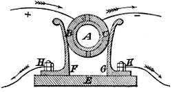
There are various forms of the magneto-electric machines, as well as of commutators, but the foregoing shows the general principle of them all.
Fig. 4.
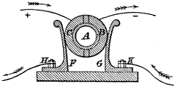
Dynamo-electric Machines.
It will now be necessary to explain the nature of a dynamo-electric machine, called, for shortness, a dynamo, and to show in what it differs from a magneto-electric machine.
I have explained how an electric current is produced by a wire passing in front of a magnet; now, this magnet may either be of the ordinary kind, or it may be what is termed an electro-magnet. Current will magnetise an iron or steel bar. One of the effects which electricity can be made to produce is the magnetising of steel bars to form the ordinary and well-known permanent magnets which are used in ships’ compasses, &c. To produce this effect, part of the wire in a circuit is made into a spiral as in Fig. 5.
Fig. 5.

Permanent magnet. The steel rod to be magnetised is placed within the spiral, and a continuous current of electricity is then sent through the wire, which causes the rod to become magnetised with a North pole at one end, and a South pole at the other. The more current is passed through the circuit, and the more turns are in the spiral, the more quickly and strongly is the rod magnetised; and it will retain its magnetism for an indefinite time if made of suitable steel. There is a point at which the metal is said to be saturated with magnetism, and the strength it has then acquired will be that which it will retain afterwards, although while under the influence of the current that strength may be considerably exceeded. Electro-magnet. If instead of a steel rod one of iron is placed in the spiral, and the current is passed through as before, it will be magnetised in the same manner; but as soon as the current is stopped, the rod loses almost all its magnetism, and if the current is then passed in the opposite direction the rod will be magnetised in the opposite way. The softer and more homogeneous is the iron, the more instantaneously will it acquire and lose its magnetism, and the greater strength of magnetism it is able to acquire. An iron bar, round which are wound a large number of turns of insulated or covered wire, constitutes an electro-magnet. Where the magneto and dynamo machines differ. The difference then between a magneto-electric and a dynamo-electric machine is, that in the former permanent magnets are used, and in the latter electro-magnets take their place. I do not intend to go into particulars as to the construction of the various dynamos in present use, as there are many books to be had in which these machines are fully described. I need merely say that in the so-called continuous-current dynamos, the whole or part of the current produced is made to pass through the coils of the electro-magnets, thus inducing in them the required magnetism. I showed how, in the magneto-electric machine, the currents are collected by means of a commutator, and it is evident that in Figs. 2, 3, and 4 there might be separate wires coming from each bobbin to B and C; and if there were more than two bobbins, there might still be two wires from each to B and C. On the other hand the collecting collar might be split into more sections; in fact there might be as many sections as bobbins. To show how the current is collected in continuous-current dynamos, I must give a short explanation of the revolving part or armature of a standard type of machine.
Fig. 6.
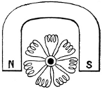
Armature of so-called continuous-current dynamo. In Fig. 6 is shown a horse-shoe magnet, with its North and South poles, N and S. Between these poles is made to revolve the armature, composed of a number of coils of wire made to form a ring like a life-buoy. The ends of the wires are made to lie along a collar on the spindle, made of some insulating material, each wire being parallel to its neighbour, and kept separate from it, as shown in Fig. 7.
Fig. 7.
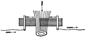
Type of commutator. These wires are so arranged that if one end of a sectional coil is on top of the spindle at a given moment, the other will be on the under side. If then, as shown in Fig. 7, a rubber of copper, made in the form of a brush of copper wire for convenience, is placed in contact with the upper Commutator brushes. part of the commutator collar, and another similar one with the lower, it is evident the circuit will be completed in the same manner as before explained.
Fig. 8.
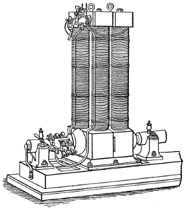
Edison Dynamo.
Current continuous in the circuit. A wire which is + when above the spindle, will be - when below it, and as the spindle revolves the current changes in the various wires from - to + as they reach the top, so that it will always therefore be + in the upper brush and - in the lower one, and will accordingly be continuous through the circuit. It will be seen in the illustrations of various continuous-current dynamos, that though their shape and arrangement differ, the mode of collecting the current is much about the same as I have described above. Figs. 8 and 9 show some of the continuous-current dynamos at present in use.
Fig. 9.
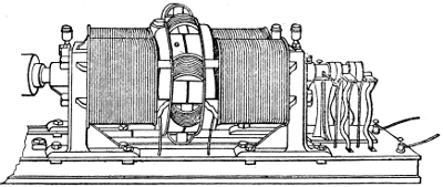
Brush Dynamo.
Alternating-current dynamos. I will now explain the nature of an alternating-current dynamo.
Fig. 10.
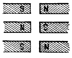
The principal difference between the continuous-and alternating-current dynamo, is in the number of magnets used. Most of the former have only four magnets, while the latter have frequently as many as thirty-two. Current not commutated. In reality, as I have shown, these are all alternating-current dynamos, only that in the so-called continuous-current ones, the current is commutated, whereas in the others it is not, but is used as it is produced. In the principal alternating-current dynamos, a number of small magnets, usually sixteen, are attached to a framework directly opposite a similar number of others of the same size, the space between the ends being only about an inch or two. These are all electro-magnets, and are wound in such manner that when excited by a current, every alternate one shall have the same magnetism, as in Fig. 10, and every opposite one a contrary magnetism.
Fig. 11.
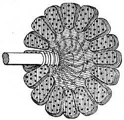
Siemens Armature.
Intense magnetic field produced. This produces an intense magnetic field between the ends of the magnets, and in this space revolves the armature. This armature, in the Siemens dynamo, is composed of a disc having as many bobbins on the periphery as there are magnets on each side of the dynamo. As each bobbin approaches each magnet a current is induced in one direction, which is reversed when the bobbin recedes; thus an alternating current is produced, which is collected by connecting the ends to insulated rings or collars on the spindle, and having small copper brushes or rubbers in contact with them. Simplicity of Ferranti armature. In the Ferranti dynamo, the armature is quite different, and much more simple, as comparison of Figs. 11 and 12 will show.
Fig. 12.
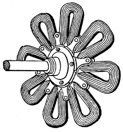
Ferranti Armature.
It consists of a copper tape bent in and out so as to form a sort of star with eight arms, the number of layers of insulated copper tape being from ten to thirty, according to requirements. The centre is made in a similar shape with bolts or rivets holding each convolution in place. The two ends of the tape are attached respectively to two collector-rings on the spindle, against which press two solid metal rubbers which carry off the current for use in the circuit. It can be shown that as each arm approaches a magnet a current will be induced in one direction, which will be reversed as each arm recedes; and therefore an alternating current will be produced. Large number of alternations of the current. As there are sixteen magnets for the armature to pass at each revolution, there must be sixteen alternations of the current during the same time, so that if the speed of the armature is 500 revolutions per minute, there will be 500 × 16 = 8000 alternations in one minute. These alternations being so extremely rapid, when this current is used for electric lighting, the steadiness of the light will be in no way affected, but will remain as constant as with a continuous current.
Fig. 13.
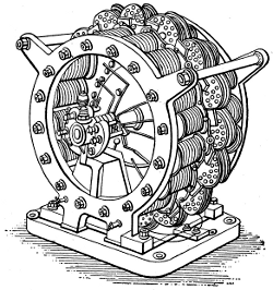
Siemens Alternating Dynamo.
Alternating current cannot be used to excite an electro-magnet. The alternating current produced by these dynamos cannot be used for exciting an electro-magnet, as the magnetism would be reversed at every alternation; a separate small dynamo of the continuous type is therefore used as an exciter to magnetise all the electro-magnets in the field, and it is usually coupled on to the same spindle, and therefore goes at the same Exciter coupled on to same spindle as dynamo. speed as the alternating-current dynamo. The exciter is usually of a size to be able to do alone about one-tenth to one-twentieth of the work that the larger machines does in the way of lighting; so that if from any cause the latter is disabled while the ship lighted by it is at sea, the exciter may be used alone to do a portion of Power of exciter if used alone. the lighting, in the first-class saloon for instance. This can only be done if the exciter is so constructed as to give the proper E.M.F. that the lamps require.
Fig. 14.
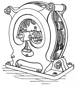
Ferranti Alternating Dynamo.
Figs. 13 and 14 are illustrations of two of the alternating current dynamos in use on board ship and elsewhere.