Chapter V · (continued 2)
Reading edition
It has taken considerable time to describe the setting up of the machine for this simple operation, but in the hands of a competent man it can be done quite rapidly. While a simple operation has been referred to in the foregoing, it will be understood that a great variety of work can be done on a machine of this type. It is not unusual to see as many as ten cutting tools operating simultaneously on a piece of work, the tools being carried by the turret, cross-slide and back facing attachment. The latter is operated from a separate cam applied to the cam-shaft and acting through levers on a back facing bar which passes through a hole in the spindle. In this back facing bar may be mounted drills, cutters, facing tools, etc. for machining the rear face of a casting held in the chuck jaws. Where extreme accuracy is required, a double back facing attachment may be used, arranged with cutters for taking both roughing and finishing cuts. The use of this attachment often saves a second operation. This automatic chucking and turning machine is also adapted for bar work, especially in diameters varying from 3 to 6 inches.
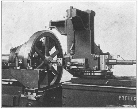
Fig. 40. Machining Flywheels in Potter & Johnston Automatic Chucking and Turning Machine
Turning Flywheel in Automatic Chucking and Turning Machine.—A typical operation on the Potter & Johnston automatic chucking and turning machine is illustrated in Fig. 40, which shows the machine arranged for turning the cast-iron flywheel for the engine of a motor truck. The rim is turned and faced on both sides and the hub is bored, reamed and faced on both sides. The flywheel casting is held in a chuck by three special jaws which grip the inside of the rim. The order of the operations is as follows:
The rear end of the hub is faced by the back facing bar; the cored hole is started by a four-lipped drill in the turret and the front end of the hub is rough-faced. (These tools are on the rear side of the turret when the latter is in the position shown in the illustration.) After the turret indexes, the hole is rough-bored by tool A and while this is being done, the outside of the rim is rough-turned by tool B held in a special bracket attached to the turret. Both sides of the rim are also rough-faced by tools C and D held at the front of the cross-slide, this operation taking place at the same time that the rim is turned and the hole is being bored.
The turret again automatically recedes and indexes, thus locating bar E and turning tool G in the working position. The hole is then finish-bored by tool E and the hub is finish-faced by blade F; at the same time the rim is finish-turned by tool G and the sides are finish-faced to the proper width by two tools held at the rear of the cross-slide. The turret automatically recedes and indexes a third time, thus locating the flat-cutter reamer-bar H in the working position and then the hole is reamed to the required diameter. This completes the cycle of operations. The total time for machining this flywheel is forty minutes.
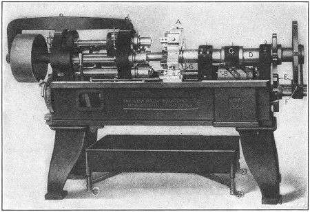
Fig. 41. New Britain Multiple-spindle Automatic Chucking Machine of Single-head Type
Automatic Multiple-spindle Chucking Machine.—An example of the specialized machines now used for producing duplicate parts, is shown in Fig. 41. This is a “New Britain” automatic multiple-spindle chucking machine of the single-head type and it is especially adapted for boring, reaming and facing operations on castings or forgings which can readily be held in chuck jaws. This particular machine has five spindles, which carry and revolve the tools. The work being machined is held stationary in the multiple chuck turret A which holds each part in line with one of the spindles and automatically indexes, so that the work passes from one spindle to another until it is finished. The turret then indexes the finished piece to a sixth or “loading position” which is not opposite a spindle, where the part is removed and replaced with a rough casting. Each pair of chuck jaws is operated independently of the others by the use of a chuck wrench. These jaws are made to suit the shape of the work.
When a single-head machine is in operation, the turret advances and feeds the work against the revolving tools so that a number of pieces are operated upon at the same time. The turret is fed by a cam drum B. Cam strips are bolted to the outside of this drum and act directly against a roller attached to the yoke C which can be clamped in different positions on the spindle D, the position depending upon the length of the work. On the opposite end of the turret spindle is the indexing mechanism E. An automatically spring-operated latch F engages notches in the rim of the dividing wheel, thus accurately locating the turret. The turret is locked by a steadyrest G, which, for each working position, automatically slides into engagement with one of the notches in the turret. This relieves the indexing mechanism of all strain.
This type of machine is also built with two spindle heads, the double-head design being used for work requiring operations on both ends. When the double-head machine is in operation, the revolving spindles and tools advance on both sides of the chuck turret, the latter remaining stationary except when indexing. The feed drums on the double-head machine are located directly beneath each group of spindles.
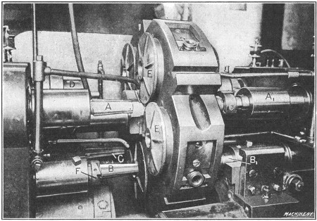
Fig. 42. Detail View of New Britain Double-head Eight-spindle Machine, Boring, Reaming and Facing Castings
Fig. 42 shows an example of work on a machine of the double-head design. This is an eight-spindle machine, there being two groups of four spindles on each side of the turret. The castings E are for the wheel hubs of automobiles. The order of the operations on one of the castings, as it indexes around, is as follows: The hole in the hub is first rough-reamed by taper reamer A and the opposite end of the hub is rough-faced and counterbored by a tool in spindle A1. When the turret indexes, this same casting is reamed close to the finished size by reamer B and the left end of the hub is rough-faced by cutter F, while a tool in the opposite spindle B1 finishes the counterboring and facing operation. At the third position, reamer C finishes the hole accurately to size, and when the work is indexed to the fourth position, the hub on the left side is finish-faced by a tool in spindle D. (The third and fourth spindles of the right-hand group are not used for this particular operation.) When the turret again indexes, the finished casting is removed and replaced with a rough one. While the successive operations on a single casting have just been described, it will be understood that all of the tools operate simultaneously and that a finished casting arrives at the unloading and loading position each time the turret indexes. Three hundred of these malleable castings are machined in nine hours.
Selecting Type of Turning Machine.—The variety of machine tools now in use is very extensive, and as different types can often be employed for the same kind of work, the selection of the best and most efficient machine is often a rather difficult problem. To illustrate, there are many different types and designs of turning machines, such as the ordinary engine lathe, the hand-operated turret lathe, the semi-automatic turning machine, and the fully automatic type, which, after it is “set up” and started, is entirely independent. Hence, when a certain part must be turned, the question is, what kind of machine should be used, assuming that it would be possible to employ several different machines? The answer to this question usually depends principally upon the number of parts that must be turned.
For example, a certain casting or forging might be turned in a lathe, which could be finished in some form of automatic or semi-automatic turning machine much more quickly. It does not necessarily follow, however, that the automatic is the best machine to use, because the lathe is designed for general work and the part referred to could doubtless be turned with the regular lathe equipment, whereas the automatic machine would require special tools and it would also need to be carefully adjusted. Therefore, if only a few parts were needed, the lathe might be the best tool to use, but if a large number were required, the automatic or semi-automatic machine would doubtless be preferable, because the saving in time effected by the latter type would more than offset the extra expense for tool equipment and setting the machine. It is also necessary, in connection with some work, to consider the degree of accuracy required, as well as the rate of production, and it is because of these varying conditions that work of the same general class is often done in machines of different types, in order to secure the most efficient results.