River Tunnels. (continued 2)
Reading edition
In the early part of the work, when the ground was being excavated ahead of the shield, the whole force, with the exception of those working in front of the shield, was engaged in erecting the iron, but, as soon as this was done, most of the men returned to the mucking, and only the iron workers continued to tighten up bolts. On the other sections, where the shield was shoved into the silt without excavating ahead, as soon as the shove was completed, the whole force was engaged in the erection of the iron and the tightening of the bolts, until they were so tight that the shield could be shoved again for another ring.
The iron was brought into the tunnel on flat cars, two segments to the car, and was lifted from the car and lowered into the invert of the shield by a block and fall and chain sling, as shown in Fig. 2, Plate XXXIX. The bottom three or four segments were pushed around into position with the erector, the head simply bearing against the longitudinal flange without being attached to the segment; the upper segments, however, were, as shown in Fig. 2, Plate XXXVIII, and Fig. 1, Plate XLI, attached to the erector, by using the expanding bar and the erector head designed by Mr. Patrick Fitzgerald, the Tunnel Superintendent. This was found to be a most convenient arrangement.
The single erector attached to the center of the shield was able to erect the iron as fast as it could be brought into the tunnel, and even when the weight of the segments was increased 25% (from 2,060 to 2,580 lb.) it always proved equal to its task, although occasionally one of the chains in the mechanism broke and delayed the work for an hour or so; but the sum of all the delays from this cause and from breaks and leaks in the hydraulic line only averaged 13 min. per ring. The operating valve which was first used was a four-spindle turning valve, but this was replaced by a sliding valve which was found to be much more satisfactory, both in ease of operation and freedom from failure.
As the iron was put into place, two of the middle bolts in each longitudinal flange and two in each circumferential one were pulled as tight as possible, and the others put in loosely; then, as soon as the ring was in position, as large a force as could be conveniently worked at one time was engaged in tightening the bolts. The shape of the tunnel depended on the thoroughness of the tightening of the bolts, and the shield was never shoved until the bolts in all the longitudinal flanges had been thoroughly tightened. In addition, all the bolts in the circumferential flanges below the axis were tightened, and at least three of the six in each segment above. After the shield had been shoved ahead, the bolts were found to have slackened, and, where the daily progress was four rings, or more, it was necessary to have a small gang of men always at this work.
PLATE XL. TRANS. AM. SOC. CIV. ENGRS. VOL. LXVIII, No. 1155. HEWETT AND BROWN ON PENNSYLVANIA R. R. TUNNELS: NORTH RIVER TUNNELS.
Sectional View of Tunnels Under North River During Construction Showing Shield, Airlocks, Platform, Piping, Lighting, etc. Click to view larger image.
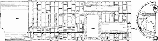
In order to get at the bolts, special platforms were necessary, and throughout the greater part of the work, a traveling platform was used. This enabled the men to reach handily all parts of the seven leading rings. This platform was supported and moved forward on wheels fixed on brackets to the tunnel, and was pulled forward by connecting chains every time the shield was shoved. In the early part of the work it was not possible to use platforms, because, in order to maintain the correct circular shape of the iron lining, it was necessary to put in temporary horizontal turnbuckles at axis level. These, however, were very convenient for supporting the planks which were used as a temporary bolting platform for the sides of the tunnel, and a temporary platform resting on 6 by 6-in. timbers across the tunnel enabled the bolts in the crown of the tunnel to be reached, while the 6 by 6-in. timbers were left in to support the emergency platform previously described (Plate XL), which extended the entire length of the tunnel.
The time taken to erect the iron lining became shorter and shorter as the tunnel organization became more perfect and the force better trained, so that, whereas, in the early part of the work, it frequently took 6 hours to erect a ring, in the latter part, when the work was nearing completion, it was a common occurrence to erect a ring in 30 min. The average time in the "heavy iron" section, which included the greater part of the work under the river, was 1 hour 4 min. for the erection of the ring and 40 min. for tightening the bolts after that had been completed, so that the total time spent by the whole gang on erection and bolting averaged 1 hour 44 min. per ring, exclusive of the time spent by the small gang which was always engaged in tightening the bolts. The average time spent in erecting and bolting, for the whole length of the tube tunnels, was 2 hours 15 min. per ring.
Tables of Progress.—Tables 24, 25, 26, and 27 have been prepared to show the time taken in the various operations at each working face.
In Tables 24, 25, 26, and 27, the following symbols are used:
A—Including assistant superintendents, foremen, and electricians, in driving the shield, erecting iron, mucking, attending to the electric lights, and repairing the pipe line.
B—Drillers, drillers' helpers, drill foremen, and nippers.
C—All men grouting.
D—Engineers and laborers wholly employed on transport between the first lock and the face.
E—In rock, one car = 0.60 cu. yd.; in sand or silt = 1.20 cu. yd. in place.
F—Time between completion of mucking and putting in first plate, spent in shoving the jacks back.
G—In ordinary iron = the whole time spent on erection and bolting. In heavy iron = the time between putting in the first plate and placing the key only.
H—Time between placing the key and starting the next shove, spent by the whole gang in tightening bolts. In addition to this, there was a small gang which spent its whole time at this work.
I—In Table 24 the first pair of bore segments is at ring 207-208. In Table 25 the first pair of bore segments is at ring 201-202. In Table 26 the first pair of bore segments is at ring 185-186. In Table 27 the first pair of bore segments is at ring 171-172. Outside diameter of tunnel = 23 ft. 0 in. Inside diameter of tunnel = 21 ft. 2 in. Length of ring = 2 ft. 6 in.
In the "Ordinary Iron" section the time is divided between mucking (which included the shoving and pushing back of the jacks) and the erection time (which included the time spent by the whole gang in tightening bolts). In the "Heavy Iron" section these times are all separated into "Mucking," "Pushing Back Jacks," "Erecting," and "Bolting," and here the bolting time included only that spent on bolts by the whole gang; in addition, there was a small gang engaged solely in tightening bolts. The lost time is the average time lost due to the break-down of hydraulic pipe lines, damaged jacks, and broken erector chains. The erection time is separated for the various kinds of rings, that is, straight ordinary rings, rings containing No. 1 bore segments, rings containing No. 2 bore segments, and taper rings, and it will be seen that, on the average, taper rings took 22 min. (or 24%) more time to erect and to bolt than ordinary ones, and that rings containing No. 2 bore segments took 14 min. (or 15%) more.
PLATE XLI. TRANS. AM. SOC. CIV. ENGRS. VOL. LXVIII, No. 1155. HEWETT AND BROWN ON PENNSYLVANIA R. R. TUNNELS: NORTH RIVER TUNNELS.
Fig. 1. Click to view larger image. Fig. 2. Click to view larger image.
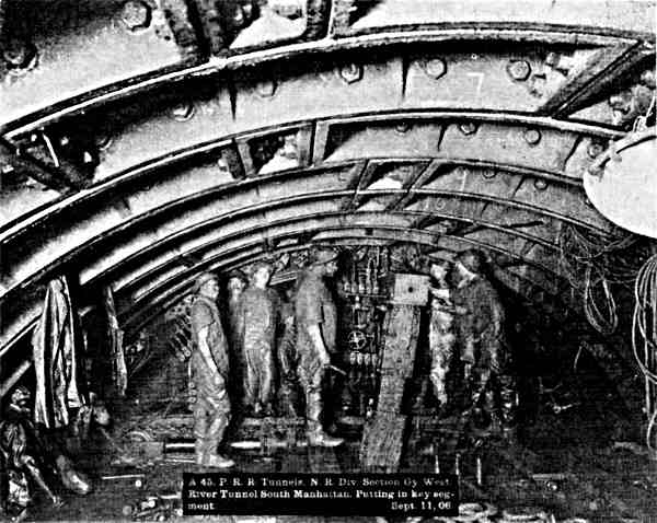
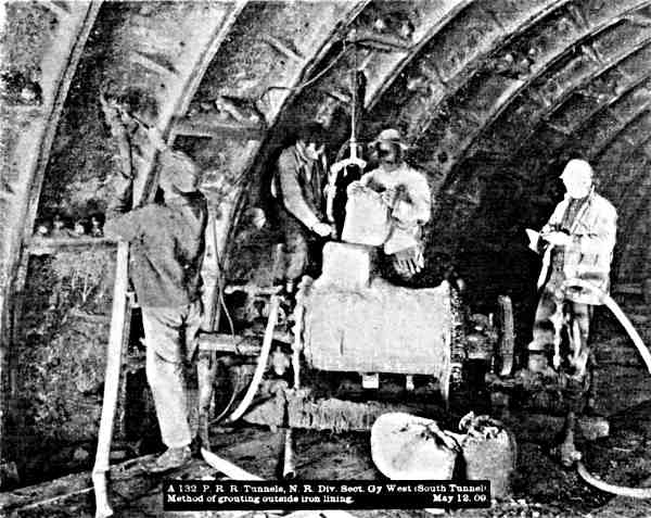
TABLE 24.— Shield-Driven Tunnel Work, Manhattan Shaft, River Tunnel North. Table showing the size of the gang, the amount of excavation, and the time per ring taken for the various operations involved in building tunnel through the several kinds of ground encountered; also the extent and nature of all the unavoidable delays.
Weight of iron Section between rings Description Ave. No. of Men Av. No. of cu. yd. per ring Time Mucking per cu. yd. Av. Time per ring, shoving and Mucking Time for Jacks Time for Ring Erection, Hrs. and Min. Bolting Time, Whole Time on Bolts After Ring is Complete. Time lost repairing hydraulic piping Total Time.
Length in feet Material Ave air Pressure Method of Excavation Shield Drilling Grouting Air trans Total Ordinary Bore 1 Bore 2 Taper Mean Ordinary Bore 1 Bore 2 Taper Mean Ordinary Bore 1 Bore 2 Taper Mean
A B C D E F G G G G G H H H H H
Ordinary 1-54 135.0 Rock 0 [P] 14 Time for jacks for light iron is included in shoving and mucking 4-00 4-21 4-04 Excavation partially completed previously.
55-80 65.0 " 19 [P] 24 7 ⅓ 1 32 41 0-31 21-00 6-04 5-30 5-57 } Bolting time for light iron is included in erection. { 27-4 26-30 26-57
81-107 65.0 Soft rock 18 [P] 22 5 2 29 41 0-33 22-30 4-26 4-26 } { 26-56 26-56
108-153 117.5 Rock 14 [P] 17 11 2 30 41 0-39 26-31 3-10 3-30 3-12 } { 29-41 30-1 29-43
154-194 102.5 Rock and earth 14 [P] 23 6 2 31 41 0-27 18-34 2-08 J. J. 2-40 2-10 } { 20-42 21-14 20-44
195-215 52.5 Silt 19 [P]Breasting 28 2 30 41 0-10 6-46 3-03 3-30 3-30 3-09 } { 9-49 10-16 10-16 9-55
216-393 445.0 " 20 [Q]8 doors 27 4 31 46 0-05 3-53 2-40 2-56 3-00 3-10 2-50 } { 0-09 6-42 6-58 7-02 7-12 6-52
394-429 90.0 Silt, piles, rip-rap 24 [P]Breasting 28 4 32 46 0-18 17-09 3-43 3-39 4-46 4-11 3-56 } { 23-79 23-25 24-32 23-57 23-42
430-509 200.0 Silt 23 [Q]1 door 24 3 27 11 0-10 1-42 3-14 4-12 3-59 3-46 3-34 } { 0-18 5-14 6-12 5-59 5-46 5-34
510-692 457.5 " 23 [Q]3 doors 26 4 30 30 0-05 1-47 2-08 2-21 2-32 2-50 2-18 } { 0-11 4-06 4-19 4-30 4-48 4-16
55-692 1,593.0 20 25 2 3 30 30 0-15 7-35 [N] 3-02 4-31 3-12 } { 0-17 10-54 12-23 11-04
216-692 1,192.5 22 26 4 30 30 0-07 3-42 [N] 2-38 2-59 3-08 1-30 2-50 } { 0-25 6-45 7-06 7-15 5-37 6-57
Heavy 693-954 655.0 Silt 24 [Q]1 door 28 6 34 11 0-12 1-02 [N] 1-52 2-05 2-15 2-29 2-0 } { 0-13 3-7 3-20 3-30 3-44 3-15
955-1,014 150.0 " 24 [Q]1 " 28 8 36 12 0-04 0-48 0-16 0-51 1-18 1-08 0-50 0-58 0-24 0-21 0-37 0-10 0-25 0 2-19 2-43 2-49 2-04 2-27
1,015-1,074 150.0 " 24 [Q]1 " 25 8 33 12 0-03 0-41 0-13 0-43 0-46 0-55 0-40 0-45 0-31 0-30 0-52 0-23 0-34 0-02 2-10 2-12 2-43 1-59 2-15
1,075-1,134 150.0 " 24 [Q]1 " 27 9 36 8 0-04 0-34 0-12 1-04 1-01 1-15 1-20 1-08 0-28 0-35 1-40 0-52 0-44 0-03 2-21 2-25 3-44 3-01 2-41
1,135-1,194 150.0 " 25 [Q]1 " 26 8 34 8 0-04 0-33 0-13 0-53 0-51 0-58 0-46 0-53 0-32 0-20 0-24 0-18 0-26 0 2-11 1-57 2-08 1-50 2-05
1,195-1,224 75.0 " 25 [Q]1 " 24 9 33 6 0-04 0-24 0-12 0-58 0-42 0-53 0-50 0-54 0-19 0-20 0-34 0-35 0-23 0 1-53 1-38 2-03 2-01 1-53
1,225-1,262 95.0 " 25 [Q]1 " 23 9 32 5 0-05 0-23 0-10 0-48 0-49 0-50 0-35 0-47 0-29 0-29 0-36 0-18 0-30 0 1-50 1-51 1-59 1-26 1-50
1,263-1,277 37.5 " 25 [Q]1 " 24 10 34 10 0-04 0-36 0-11 0-47 0-50 0-52 0-48 0-52 0-23 0-23 0-41 0-23 0-27 0 1-57 2-0 2-20 1-58 2-06
1,278-1,307 75.0 " 25 [Q]1 " 21 10 31 17 0-04 1-09 0-10 1-03 1-01 1-06 0-00 1-04 0-33 0-34 0-51 0-0 0-36 0 2-55 2-54 3-16 0-0 2-59
1,308-1,326 47.5 " 28 [Q]1 " 27 11 38 22 0-05 1-39 0-18 1-25 1-48 1-50 0-50 1-31 0-49 0-42 0-58 0-25 0-48 0 4-11 4-27 4-45 3-12 4-16
955-1,326 930.0 24 26 9 35 11 0-04 0-41 0-13 0-55 0-59 1-03 0-55 0-58 0-29 0-27 0-49 0-31 0-32 0 2-18 2-20 2-46 2-20 2-24
693-1,326 1,585.0 24 27 8 35 12 0-04 0-51 [N] 1-27 1-34 1-41 1-38 1-31 [O] 0-06 2-24 2-31 2-38 2-35 2-28
SUMMARY
Weight of iron Section between rings Description Ave. No. of Men in Gang Average No. of cubic yard per ring Time mucking, per cubic yard Average Time per Ring Unavoidable Delays (Not Included in Average Time per Ring).
Length in feet Material Ave. air Pressure Method of Excavation Shield Drilling Grouting Air Trans Total Shoving and mucking[N] Erection[O] Lost time Total Items Time hrs--min
Ordinary 1-54 135.0 Rock 0 [P] 14 4-14 First bulkhead 172-00
55-194 350.0 Earth and rock 16 [P] 22 6 ⅓ 2 30 41 0-32 21-44 4-04 25-48 Second bulkhead 119-00
195-393 497.5 Silt 20 [P]Breasting 27 4 31 38 0-07 4-11 2-52 0-09 7-12 Grouting 200-00
394-440 117.5 " 24 [P]Breasting 28 4 32 41 0-18 11-54 4-17 1-41 17-52 Blowout 73-00
441-692 630.0 " 23 [Q]3 doors 25 4 29 17 0-06 2-04 2-34 0-42 5-20 Cradle 100-00
216-692 1,192.5 22 26 4 30 30 0-07 3-42 2-50 0-25 6-57 Total 664-00
55-692 1,595.0 20 25 2 3 30 30 0-15 7-35 3-12 0-17 11-04 Per ring 0-39
Heavy 693-1,326 1,585.0 Silt 24 [Q]1 door 27 8 35 12 0-04 0-51 1-31 0-06 2-28
All 55-1,326 3,180.0 22 26 6 32 21 0-10 4-13 2-22 0-12 6-47
TABLE 25.— Shield-Driven Tunnel Work, Manhattan Shaft, River Tunnel South. Table showing the size of the gang, the amount of excavation, and the time per ring taken for the various operations involved in building tunnel through the several kinds of ground encountered; also the extent and nature of all the unavoidable delays.
Weight of iron Section between rings Description Average No. of Men in Gang Av. No. of cu. yd. per ring Time Mucking, per cu. yd. Av. time per ring shoving and Mucking Time for Jacks Time for Ring Erection, Hrs. and Min. Bolting Time, Whole Time on Bolts After Ring is Complete. Time lost repairing hydraulic piping Total Time.
Length in feet Material Ave air pressure Method of Excavation Shield Drilling Grouting Air trans Total Ordinary Bore 1 Bore 2 Taper Mean Ordinary Bore 1 Bore 2 Taper Mean Ordinary Bore 1 Bore 2 Taper Mean
A B C D E F G G G G G H H H H H
Ordinary 1-68 170.0 Rock 0 [R] 20 5 5 2 32 41 0-14 9-53 Time for jacks for light iron is included in shoving and mucking 5-27 4-32 5-07 Excavation partially completed previously. Bolting time for light iron is included in erection. 15-20 14-25 15-00
69-95 67.5 Rock and earth 13 [R] 22 8 2 32 41 0-24 16-18 3-02 2-40 3-00 19-20 18-58 19-18
96-141 115.0 Rock 10 [R] 21 13 2 36 70 0-16 18-16 2-08 2-27 2-09 0-03 20-27 20-46 20-28
142-191 125.0 Rock and earth 15 [R] 24 7 2 33 52 0-20 17-27 2-08 J J 2-04 2-08 0-12 19-47 19-43 19-47
192-203 30.0 Silt 18 [R]Breasting 23 3 26 36 0-13 7-58 2-27 6-00 2-10 3-15 2-47 1-20 11-45 15-18 11-28 12-33 12-05
204-388 462.5 " 18 [S]7 doors 27 3 30 37 0-05 3-19 2-41 2-49 2-54 2-56 2-47 0-05 6-05 6-13 6-18 6-20 6-11
389-429 102.5 Silt, piles and rip-rap. 22 [S] 6 doors [R]Breasting 24 4 28 40 0-17 12-42 3-15 2-36 5-03 3-26 3-27 0-38 16-35 15-56 18-23 16-46 16-47
430-504 187.5 Silt 21 [S]3 doors 23 5 28 20 0-06 1-51 2-53 3-17 3-00 2-57 2-59 0-39 5-23 5-47 5-30 6-27 5-29
505-629 312.5 " 22 [S]4 doors 25 6 31 27 0-05 2-20 2-23 2-40 2-45 2-28 2-30 0-23 5-06 5-23 5-28 5-11 5-13
630-692 157.5 " 23 [S]2 doors. 24 8 32 22 0-05 1-53 1-54 2-10 2-22 2-23 2-02 0-08 3-55 4-11 4-23 4-24 4-03
204-692 1,222.5 21 25 5 30 30 0-07 3-27 [T] 2-34 2-45 2-58 2-35 2-42 0-18 6-19 6-30 6-43 6-20 6-27
69-692 1,560.0 17 23 4 0 3 30 36 0-11 6-40 [T] 2-47 3-18 2-52 0-15 9-42 10-13 9-47
Heavy 693-766 185.0 Silt 24 [S]2 doors 21 6 27 22 0-05 1-35 0-25 1-18 1-44 1-30 1-40 1-25 0-43 1-09 0-52 0-50 0-49 0-07 4-08 5-00 4-29 4-37 4-21
767-806 100.0 " 24 [S]2 " 22 7 29 22 0-05 1-19 0-21 1-00 0-56 1-37 1-21 1-08 0-38 0-24 0-43 0-38 0-42 0-02 3-20 3-02 4-02 3-41 3-32
807-900 235.0 " 24 [S]1½ " 23 8 31 19 0-05 1-11 0-17 0-58 1-13 1-08 1-12 1-04 0-39 0-34 0-56 0-31 0-40 0-06 3-11 3-21 3-38 3-17 3-18
901-933 82.5 " 25 [S]1 door 30 10 40 19 0-04 1-13 0-09 0-59 1-05 0-59 1-00 0-34 0-26 1-47 0-43 0-05 3-00 2-58 4-13 3-10
934-988 137.5 " 25 [S]1 " 30 11 41 16 0-04 0-54 0-12 0-49 0-44 0-56 0-50 0-28 0-34 0-34 0-30 0-06 2-29 2-30 2-42 2-32
989-1,043 137.5 " 25 [S]1 " 28 11 39 13 0-05 0-52 0-14 0-51 0-44 0-52 1-14 0-52 0-33 0-24 0-51 0-35 0-35 0-04 2-34 2-18 2-53 2-59 2-37
1,044-1,053 25.0 " 26 [S]1 " 25 9 34 16 0-07 0-40 0-15 1-04 1-15 0-50 0-55 1-02 0-23 0-38 0-30 0-55 0-36 3-22 3-48 3-15 3-45 3-33
1,054-1,068 37.5 26 [S]1 " 26 9 35 8 0-05 0-36 0-08 0-57 0-40 1-02 0-56 0-33 0-25 0-35 0-32 2-14 1-49 2-21 2-12
1,069-1,110 105.0 " 26 [S]1 " 30 11 41 14 0-06 1-00 0-15 0-48 0-54 1-06 1-31 0-56 0-32 0-40 0-48 0-46 0-37 0-05 2-40 2-54 3-14 3-37 2-53
693-1,110 1,045.0 25 25 8 33 18 0-05 1-29 [T] 1-01 1-08 1-09 1-19 1-05 0-37 0-39 0-52 0-40 0-40 0-05 3-12 3-21 3-35 3-33 3-19
All 204-1,110 2,267.5 23 25 6 31 25 0-06 2-35 [T] 2-09 2-19 2-33 2-19 2-17 [U] 0-12 4-56 5-06 5-20 5-06 5-04
SUMMARY
Weight of iron Section between rings Description Ave. No. of Men in Gang Average No. of cubic yards per ring Mucking, per cubic yard Average Time per ring Unavoidable Delays (not Included in Average Time per Ring).
Length in feet Material Ave. air pressure Mehod of Excavation Shield Drilling Grouting Air Trans Total Shoving and mucking[T] Erection [U] Lost time Total Items Time hrs min
Ordinary 1-68 170.0 Rock 0 [R] 20 5 5 5 32 41 0-14 9-53 5-07 15-00 First bulkhead 160--00
69-191 307.5 Rock and earth 13 [R] 22 9 2 33 54 0-19 17-20 2-26 0-05 19-51 Second bulkhead 157--45
389-429 102.5 Silt piles and rip-rap 22 [R] Breasting [S]6 doors 24 4 28 40 0-17 12-42 3-27 0-38 16-47 Blowout 69--45
430-692 657.5 Silt 22 [S]3 doors 24 6 30 24 0-05 1-58 2-29 0-22 4-49 Waiting for heavy iron 64--0
204-692 1,222.5 21 25 5 30 30 0-07 3-27 2-42 0-18 6-27 Total 715--30
69-692 1,560.0 17 23 4 0 3 30 36 0-11 6-40 2-52 0-15 9-47 Per ring 0--39
Heavy 693-1,110 1,045.0 25 [S]1 door 25 8 33 18 0-05 1-29 1-45 0-06 3-19
All 69-1,110 2,605.0 20 24 5 31 29 0-09 4-36 2-25 0-14 7-15
TABLE 26.— Shield-Driven Tunnel Work, Weehawken Shaft, River Tunnel North. Table showing the size of the gang, the amount of excavation, and the time per ring taken for the various operations involved in building tunnel through the several kinds of ground encountered; also the extent and nature of all the unavoidable delays.
Weight of iron Section between rings Description Ave. No. of Men in Gang Av. No. of cu. yd. per ring Time Mucking, per cu. yd. Av. Time per ring, shoving and mucking Time for Jacks Time for Ring Erection, Hrs. and Min. Bolting Time, Whole Time on Bolts After Ring is Complete. Time lost repairing hydraulic piping Total Time.
Length in feet Material Ave air Pressure Method of Excavation Shield Drilling Grouting Air trans Total Straight Bore 1 Bore 2 Taper Mean Straight Bore 1 Bore 2 Taper Mean Straight Bore 1 Bore 2 Taper Mean
A B C D E F G G G G G H H H H H
Ordinary 1-24 60.0 Rock 0 [X] 9 .04 0 0 10 46 0-06 4-32 Time for jacks for light iron is included in shoving and mucking. 6-23 6-23 Excavation partially completed previously. 10-55 10-55
25-55 77.5 " 20 [X] 14 5 0.5 1 21 46 0-51 39-33 4-25 5-10 4-29 43-58 44-43 44-02
56-72 42.5 Mixed sand and rock 10 [X]Breasting 22 2 .09 2 26 44 0-21 15-05 2-53 3-15 2-55 0-04 18-02 18-24 18-04
73-165 232.5 Sand and gravel 10 [X] " 22 0 0.1 2 24 39 0-11 6-56 2-27 2-21 2-26 Bolting time for light iron is included in erection. 0-09 9-32 9-26 9-31
166-184 47.5 Sand and silt with piles 20 [X] Breasting and cutting piles 22 0 .38 3 25 42 0-09 6-19 2-31 J J 6-30 2-37 0-07 8-57 12-56 9-03
185-253 172.5 Silt and piles 24 23 0 .71 3 26 43 0-09 6-13 1-57 2-44 2-52 2-00 2-15 0-15 8-25 9-12 9-20 8-28 8-43
254-293 100.0 Silt 26 [Y]8 doors 22 0 0 3 25 6 0-18 1-45 1-58 1-57 2-15 2-45 2-02 0-14 3-57 3-56 4-14 4-44 4-01
294-301 20.0 " 27 19 0 0 2 21 0 1-08 0-58 1-45 1-50 1-17 2-06 2-53 2-58 2-25
302-307 15.0 " 27 [Y]8 doors 21 0 0 2 23 26 0-09 4-03 2-20 1-40 1-55 2-57 2-22 6-23 5-43 5-58 7-00 6-25
308-342 87.5 " 28 19 0 0 2 21 0 0 0-36 2-00 1-34 2-42 1-58 2-02 2-36 2-10 3-18 2-29 2-38
343-347 12.5 " 28 [Y]8 doors 15 0 0 2 17 2 0-36 1-11 2-15 2-20 2-43 2-33 0-39 4-05 4-10 4-43 4-23
348-459 280.0 " 28 20 0 0 3 23 0 0 0-33 2-03 2-04 2-09 2-23 2-06 0-14 2-50 2-51 2-56 3-10 2-53
460-494 87.5 " 28 [Y]8 doors 21 0 0 3 24 9 0-09 1-23 2-49 2-30 2-50 1-50 2-38 0-27 4-39 4-20 4-40 3-40 4-28
495-513 47.5 " 28 8 " 23 0 0 4 27 17 0-05 1-28 2-35 2-23 1-55 2-10 2-26 4-03 3-51 3-23 3-38 3-54
514-605 230.0 " 28 8 " 25 0 0 4 29 26 0-04 1-44 2-12 2-34 2-29 2-15 2-19 3-56 4-18 4-13 3-59 4-03
606-624 47.5 " 28 8 " 24 0 0 4 28 16 0-04 1-07 1-54 2-33 2-16 1-35 2-04 3-01 3-40 3-23 2-42 3-11
625-640 40.0 " 28 8 " 38 0 0 5 43 24 0-03 1-13 2-14 2-55 2-35 2-46 2-28 3-27 4-08 3-48 3-59 3-41
25-640 1,540.0 20
185-640 1,140.0 26 23 0 0.2 3 26 16 0-07 1-58 [V] 2-07 2-19 2-26 2-15 2-13 0-09 4-14 4-26 4-33 4-22 4-20
Heavy 641-647 17.5 Silt 28 [Y]8 doors 24 0 0 6 30 19 0-04 0-08 [V] 1-20 2-08 1-65 1-40 1-41 0-40 0-35 1-25 0-55 0-47 3-08 3-51 4-28 3-43 3-36
648-751 260.0 " 28 [Y]8 " 22 0 0 4 26 14 0-03 0-36 0-12 1-21 1-22 1-26 1-55 1-23 0-31 0-29 0-38 0-30 0-32 0-12 2-52 2-51 3-04 3-25 2-55
752-795 110.0 " 28 [Y]8 " 18 0 0 7 25 10 0-03 0-29 0-14 0-46 1-25 1-31 2-37 1-10 0-48 0-31 0-44 0-35 0-43 0-05 2-22 2-44 3-03 4-00 2-41
796-825 75.0 " 28 [Y]8 " 19 0 0 10 28 5 0-08 0-40 0-11 0-48 1-31 1-34 0-53 1-03 0-31 1-03 0-49 3-27 0-51 2-10 3-25 3-14 5-11 2-45
826-854 72.5 " 28 [Y]8 " 17 0 0 3 20 15 0-03 0-48 0-19 0-54 1-12 1-02 1-23 1-01 0-22 0-37 0-38 0-20 0-27 0-06 2-29 3-02 2-53 2-56 2-41
855-881 67.5 " 28 [Y]8 " 23 0 0 9 32 7 0-05 0-33 0-16 0-59 0-45 1-15 1-20 1-01 0-22 0-21 0-45 0-40 0-26 0-45 2-55 2-40 3-34 3-34 3-01
882-982 252.5 " 28 [Y]8 " 20 0 0 8 28 10 0-02 0-20 0-14 0-49 1-02 1-01 0-50 0-54 0-41 0-36 0-36 0-15 0-39 0-12 2-16 2-24 2-23 1-51 2-19
983-990 20.0 " 28 [Y]8 " 21 0 0 7 28 17 0-02 0-34 0-14 0-40 0-40 0-48 0-44 1-15 0-15 0-28 0-48 2-43 1-43 2-04 2-20
991-1,049 147.5 " 28 [Y]8 " 23 0 0 7 30 8 0-03 0-21 0-11 0-40 0-48 0-39 0-41 0-41 0-34 0-55 0-41 1-53 1-54 2-06 1-54
1,050-1,074 62.5 " 28 [Y]8 " 24 0 0 9 33 7 0-03 0-18 0-10 0-43 0-44 0-46 0-40 0-43 0-35 1-15 0-07 0-35 0-48 0-04 1-50 2-31 2-25 1-47 2-03
1,075-1,110 90.0 " 28 [Y]8 " 25 0 0 10 35 16 0-02 0-33 0-12 0-50 1-02 1-06 0-58 0-55 0-35 0-46 0-58 2-10 0-41 0-21 2-31 2-54 2-10 4-14 2-42
641-1,110 1,175.0 28 21 0 0 7 28 8 0-04 0-30 0-14 0-56 1-08 1-12 1-29 1-02 0-36 0-36 0-44 0-54 6-38 0-11 2-27 2-27 2-51 3-18 2-35
All 185-1,110 2,315.0 28 22 0 0.1 5 27 12 0-07 1-20 0[V] 1-48 2-01 2-11 2-17 1-56 [W] 0-10 3-18 3-31 3-41 3-47 3-26
SUMMARY
Weight of iron Section between rings Description Average No. of Men in Gang Average No. of cubic yards per ring Time mucking, per cubic yard Average Time per Ring. Unavoidable Delays (not Included in Average Time per Ring).
Length in feet Material Ave. air Pressure Method of Excavation Shield Drilling Grouting Air trans Total Shoving and mucking [V] Erection [W] Lost time Total Items Time hrs min
Ordinary 1-24 60.0 Rock 0 [X] 9 .04 0 0 10 46 0-06 4-32 6-23 0-00 10-55 First bulkhead 132-00
25-55 77.5 " 20 [X] 14 5 0.5 1 21 46 0-51 39-33 4-29 0-00 44-02 Second bulkhead 158-50
56-72 42.5 Mixed sand and rock 10 [X]Breasting 22 2 .09 2 26 44 0-21 15-05 2-55 0-04 18-04 Grouting 240-00
73-165 232.5 Sand & gravel 10 [X]Breasting 22 0 .1 2 24 39 0-11 6-56 2-26 0-09 9-31 Old cave-in 234-00
166-184 47.5 Sand and silt with piles 20 [X]Breasting and cutting piles 22 0 .38 3 25 42 0-09 6-19 2-37 0-07 9-03 Shoving tube 128-00
185-253 172.5 Silt w/ piles 24 [X]Breasting and cutting piles 23 0 .71 3 26 43 0-09 6-13 2-15 0-05 8-43 - -
254-640 110.0 Silt 26 [Y]Doors 22 0 0 3 25 11 0-07 1-13 2-20 0-08 3-41 Total 892-50
25-640 1,540.0 20 [Y]Doors 21 0.3 .12 3 24 24 0-14 5-06 2-24 0-08 7-38 per ring 0-49
Hvy 641-1,110 1,175.0 28 21 0 0 7 28 8 0-04 0-44 1-40 0-11 2-35
All 25-1,110 2,715.0 26 21 0.1 0.1 3 24 17.1 0-12 3-13 3-05 0-09 5-27
TABLE 27.— Shield-Driven Tunnel Work, Weehawken Shaft, River Tunnel South. Table showing the size of the gang, the amount of excavation, and the time per ring taken for the various operations involved in building tunnel through the several kinds of ground encountered; also the extent and nature of all the unavoidable delays.
Weight of iron. Section between rings. Description. Ave. No. of Men in Gang. Av. No. of cu. yd. per ring. Time Mucking, per cu. yd. Av. Time per ring Shoving and Mucking. Time for Jacks. Time for Ring Erection, Hrs. and Min. Bolting Time, (Whole Time on Bolts After Ring is Complete.) Time lost repairing hydraulic piping. Total Time.
Length in feet. Material. Ave. air Pressure. Method of Excavation. Shield. Drilling. Grouting. Air trans. Total. Straight. Bore 1. Bore 2. Taper. Mean. Straight. Bore 1. Bore 2. Taper. Mean. Straight. Bore 1. Bore 2. Taper. Mean.
A B C D E F G G G G G H H H H H
Ordinary. 1-27 67.5 Rock 9 [B] Excavation partially completed previously. 8-30 3-45 8-08 Bolting time for light iron is included in erection. 0-14 21-11 16-26 20-49
28-42 37.5 " 12 [B] 13 4 1 1 19 48.7 0-25 20-33 4-23 4-00 4-21 0-12 25-08 24-45 25-06
43-58 40.0 Rock or gravel 12 [B] 19 2 2 2 25 44.2 0-46 33-44 4-16 5-45 4-44 1-15 39-15 40-44 39-43
59-153 237.5 Gravel and sand 16 [B]Breasting 25 1 4 30 39.0 0-12 8-06 2-19 4-18 2-23 0-30 10-55 12-54 10-59
154-170 42.5 Sand and silt with piles 18 " 26 1 5 32 41.6 0-10 7-10 2-00 J. J. 1-48 1-59 0-00 9-10 J. J. 8-58 9-09
171-236 165.0 Silt with piles 22 Top half 22 1 3 26 42.6 0-10 7-23 2-36 2-55 2-58 1-24 2-35 0-05 10-04 10-23 10-26 8-52 10-03
237-259 57.5 Silt 25 [C]1 door 18 1 3 22 13.8 0-11 2-29 3-01 2-05 1-28 2-00 2-32 0-20 5-50 4-54 4-17 4-49 5-21
260-302 107.5 " 27 [C]1 door 15 2 17 0 0-32 2-34 2-35 3-38 4-28 3-05 0-08 3-14 3-15 4-18 5-08 3-45
303-350 120.0 " 27 [C]8 doors 15 4 19 6.9 0-07 0-52 2-59 2-28 2-37 1-44 2-41 0-07 3-58 3-27 3-36 2-43 3-40
351-378 70.0 " 27.5 [C]8 " 18 6 24 0 0-33 2-05 2-32 2-48 2-00 2-18 0-17 2-55 3-22 3-38 2-50 3-08
379-424 115.0 " 27.5 [C]8 " 19 4 23 6.9 0-07 0-48 3-34 2-51 3-18 3-19 3-22 0-25 4-47 4-09 4-31 4-32 4-35
425-522 245.0 " 28 [C]1 door 19 4 23 6.7 0-06 0-45 3-09 3-51 3-00 3-28 3-16 0-16 4-10 4-52 4-01 4-29 4-17
523-625 257.5 " 28 [C]1 " 20 4 24 0 0-32 1-36 1-37 1-47 1-51 1-39 0-12 2-20 2-21 2-31 2-35 2-23
171-625 1,137.5 27 19 4 23 9.7 0-11 1-44 [Z] 2-37 2-41 2-41 2-32 2-38 0-13 4-34 4-38 4-38 4-29 4-35
28-625 1,495.0 25 19 .8 0.8 3.4 24 17.8 0-14 4-14 [Z] 2-41 0-16 7-11
Heavy. 626-649 57.5 Silt 28 [C]1 door 16 3 19 12.2 0-12 2-23 [Z] 2-19 2-30 2-05 1-42 2-16 1-01 1-04 1-04 0-50 1-01 0-32 6-15 6-29 6-04 5-27 6-12
650-733 210.0 " 28 [C]8 doors 19 4 23 13.5 0-57 0-13 1-42 1-24 1-47 1-48 1-39 1-15 0-52 0-55 0-42 1-07 0-32 4-39 3-58 4-24 4-12 4-28
734-753 50.0 " 28 [C]8 " 24 5 29 8.3 0-05 0-41 0-17 1-06 1-55 0-38 1-20 1-12 0-38 0-44 1-13 0-20 0-44 0-06 2-48 3-43 2-55 2-44 3-00
754-844 227.5 " 28 [C]8 " 26 8 34 12.8 0-04 0-51 0-16 1-19 1-41 1-52 0-50 1-29 0-39 0-50 0-54 0-40 0-44 0-25 3-30 4-08 4-18 3-02 3-45
845-859 37.5 " 28 [C]8 " 27 9 36 5.6 0-07 0-39 0-19 1-24 1-08 1-10 1-20 0-45 0-15 0-15 0-37 0-48 3-55 3-09 3-11 3-43
860-899 100.0 " 28 [C]8 " 24 8 33 16.5 0-02 0-39 0-13 1-00 1-05 1-13 1-04 0-59 0-32 0-49 0-52 0-07 2-58 2-36 3-01 2-55
900-935 90.0 " 28 [C]1 door 25 7 32 11.5 0-03 0-29 0-14 0-47 1-13 0-52 1-10 0-52 0-39 0-43 0-32 0-20 0-38 0-04 2-18 2-43 2-11 2-17 2-17
936-963 70.5 " 28 [C]1 " 25 8 33 5.9 0-03 0-19 0-15 0-59 0-47 0-55 0-56 0-34 0-16 0-41 0-32 0-37 2-44 2-14 2-47 2-39
964-1,003 100.0 " 28 [C]1 " 25 10 35 8.1 0-03 0-27 0-10 0-51 0-52 1-05 0-53 0-32 0-45 0-37 0-35 0-16 2-16 2-30 2-35 2-21
1,004-1,060 142.5 " 28 [C]1 " 26 10 36 8.7 0-03 0-30 0-15 1-01 1-09 1-05 0-45 1-03 0-54 0-37 0-49 0-40 0-49 0-24 3-04 2-55 3-03 2-34 3-01
1,061-1,110 125.0 " 28 [C]1 " 37 10 47 6.2 0-03 0-19 0-10 0-42 0-49 0-54 0-45 0-45 0-24 0-26 0-39 0-25 0-27 0-00 1-35 1-44 2-02 1-39 1-41
1,111-1,238 320.0 " 28 [C]1 " 30 9 39 15.6 0-02 0-38 0-16 0-48 1-06 1-04 1-23 0-56 0-36 0-34 0-57 1-12 0-41 0-02 2-20 2-36 2-57 3-31 2-33
1,239-1,312 185.0 " 28 39 9 38 13.0 0-03 0-36 0-18 1-04 1-01 1-02 1-15 1-07 0-39 0-43 1-12 0-59 0-50 0-10 2-47 2-48 3-18 3-18 3-01
626-1,312 1,717.5 " 28 35 8 33 10.6 0-04 0-42 0-14 1-06 1-15 1-16 1-18 1-10 0-45 0-40 0-52 0-54 0-47 0-16 3-03 3-07 3-20 3-24 3-09
All 171-1,312 2,855.0 28 23 6 29 10.2 0-07 1-15 [Z] 2-09 2-13 2-21 2-20 2-13 [A] 0-15 3-39 3-43 3-51 3-50 3-43
SUMMARY
Weight of iron. Section between rings. Description. Ave. No. of Men in Gang. Average No. of cubic yards per ring. Time mucking, per cubic yard. Average Time per Ring. Unavoidable Delays (not Included in Average Time per Ring).
Length in feet. Material. Ave. air Pressure. Method of Excavation. Shield. Drilling. Grouting. Air Trans. Total. Shoving and mucking. [Z] Erection.[A] Lost time. Total. Items. Time, hrs. min.
Ordinary. 28-42 37.5 Rock 12 [B]Breast 13 4 1 1 19 48.7 0-25 20-33 4-21 0-12 25-06 First bulkhead 80-00
43-58 40.0 Rock and gravel 12 " 19 2 2 2 25 44.2 0-46 33-44 4-44 1-15 39-43 Second bulkhead 156-00
59-153 237.5 Gravel and sand 16 " 25 1 4 30 39.0 0-12 8-06 2-23 0-30 10-59 Grouting rock sections 280-00
154-170 42.5 Sand or silt, with piles 18 " 26 1 5 32 41.6 0-10 7-10 1-59 0-0 9-09 Blow-outs 222-00
171-236 165.0 Silt with piles 22 " 22 1 3 26 42.6 0-10 7-23 2-35 0-05 10-03 Shield repairs 326-40
237-259 57.5 Silt 25 [C]1 door 18 1 3 22 13.8 0-11 2-29 2-32 0-20 5-21 Horz. timbers 69-30
260-625 915.0 " 27 1 " 18 4 22 3.6 0-06 0-40 2-39 0-14 3-33 Total 1,134-10
28-625 1,495.0 25 19 .8 0.8 3.4 24 17.8 0-14 4-14 2-41 0-16 7-11 Per ring 0-53
Heavy. 626-1,312 1,717.5 Silt 28 25 8 33 10.6 0-4 0-56 1-57 0-16 3-09
All. 28-1,312 3,212.5 26 21 5 26 14.1 0-10 2-28 2-18 0-15 5-01
The average time taken for each operation at all the working faces is given in Table 28. The work has been subdivided into the different kinds of ground encountered.
The progress, as shown by the amount of work done each month by each shield, is given in Table 29.
TABLE 28. —Shield-Driven Tunnel Work.—Total Number of Rings Erected and Shifts Worked by All Four Shields in Contracts Gy-West and Gj, and the Average Size of Gang, Amount of Excavation and Time Taken per Ring for the Various Operations Involved in Building Tunnel in Each of the Several Kinds of Ground Encountered; Also the Extent and Nature of All the Unavoidable Delays.
Weight of iron. Description of Material. Total No. of rings. Total No. of feet. Total number of 8-hour shifts. Average air pressure. Ave. No. of Men in Gang. Cu. yd. per ring. Time per cu. yd. Average Time per Ring. Ave. Unavoidable Delay per Working Face.
Shield. Drilling. Grouting. Air trans. Total. Shoving and mucking. Erecting. Lost time. Total. Items not included in previous figures. Time.
Unit. Unit. Hrs. Min. Hrs. Min. Hrs. Min. Hrs. Min. Ave. unit.
Unit. Unit. Unit. Unit. Unit. K L M Hrs. Min.
Ordinary Rock. 165 412.5 597 16 18 9 0.25 1 28 51 0-27 25 15 3 41 0 02 28 58 1st Bulkhead 136 00
Rock and earth and rock and gravel. 177 442.5 500 14 22 5 0.3 2 30 45 0-26 19 31 2 55 0 11 22 37 2d " 147 54
Sand and gravel (unobstructed), NJ 188 470.0 241 13 24 0.6 3 27 39 0-12 7 31 2 24 0 20 10 15 Grouting 246 00
Sand and silt (with piles.) 171 427.5 199 22 23 1.0 3 27 43 0-09 6 46 2 24 0 09 9 19 Blow-outs 91 11
Silt under R. R. tracks, NY 396 990.0 355 19 27 3 30 42 0-06 4 09 2 51 0 10 7 10 Miscellaneous 230 33
Rip-rap and silt under bulkhead. 77 192.5 193 23 26 4 30 43 0-21 14 47 3 41 1 34 20 02 Total 851 38
Total mixed and difficult ground. 1,174 2,935.0 2,085 17 22 4 0.3 3 29 43 0-18 11 02 2 54 0 16 14 12
Silt--ordinary iron 1,302 3,255.0 676 25 22 4 26 12 0-07 1 20 2 35 0 14 4 12
Heavy Silt--heavy iron. 2,209 5,522.5 791 26 25 8 33 12 0-05 0 58 1 44 0 10 2 52
Silt--ord and heavy iron under river. 3,511 8,777.5 1,467 26 24 6 30 12 0-06 1 09 2 05 0 12 3 26
Grand total. 4,685 11,712.5 3,552 21 23 2 0.2 4 29 20 0-11 3 33 2 15 0 13 6 01
Average delay per ring—0 hrs. 44 min. Average rings built by one shield = 1,146¼.
Average time per ring. 6 hr 01 min
Delays. 44 min
—————
Total time per ring. 6 hr 45 min
Note.—The "unavoidable delays" included in this table do not embrace the periods during which the work was at complete or partial standstill due to experiments and observations, shortage of iron due to change of design, and holidays.
K-Including time for jacks. L-Including time spent by the whole gang on bolting; in addition to this there was a small gang which spent its whole time bolting. M-Chiefly due to breakdowns of hydraulic lines and erector.
Air Pressure.—The air pressure varied from 17 to 37 lb. Behind the river line it averaged 17 lb. and under the river 26 lb. Behind the river lines the pressure was generally kept about equal to the water head at the crown, except where at Weehawken, as previously described, this was impossible.
In the silt the pressure was much lower than the hydrostatic head at the crown, but if it became necessary to make an excavation ahead of the shield, for example at the junction of the shields, the air pressure required was about equal to the weight of the overlying material, namely, the water and the silt, as the silt, which weighed from 97 to 106 lb. per cu. ft. and averaged 100 lb. per cu. ft., acted like a fluid.
TABLE 29.— Monthly Progress of Shield-Driven Tunnel Work.
Month North Manhattan. South Manhattan. North Weehawken. South Weehawken. Average progress per shield lin. ft. per month.
Number of rings erected. Station of leading ring. Lin. ft. for month. Number of rings erected. Station of leading ring. Lin. ft. for month. Number of rings erected. Station of leading ring. Lin. ft. for month. Number of rings erected. Station of leading ring. Lin. ft. for month.
For month. To date. For month. To date. For month. To date. For month. To date.
1905
May 26 26 200 + 83.7 63.7 15.9
June 26 52 201 + 49.0 65.3 24 24 260 + 76.6 59.3 12 12 260 + 70.0 30.0 38.6
July 28 80 202 + 19.2 70.2 12 36 260 + 46.6 30.0 15 27 260 + 32.4 37.6 34.4
Aug 26 106 202 + 84.3 65.1 15 51 260 + 09.1 37.5 16 43 260 + 07.4 25.0 31.9
Sept 21 127 203 + 36.8 52.5 31 31 200 + 96.4 76.4 1 52 260 + 06.6 2.5 18 61 259 + 47.2 60.2 47.9
Oct 25 152 203 + 99.4 63.6 45 76 202 + 09.2 112.8 10 62 259 + 81.5 25.1 20 81 258 + 97.2 50.0 62.9
Nov 31 183 204 + 76.9 77.5 31 107 202 + 86.5 77.3 29 91 259 + 09.0 72.5 39 120 257 + 99.7 97.5 81.2
Dec 59 242 206 + 24.6 147.7 34 141 208 + 71.8 85.3 46 137 257 + 94.0 115.0 77 197 256 + 07.1 192.6 135.1
1906
Jan 94 336 208 + 59.8 235.2 27 168 304 + 39.4 67.6 77 214 256 + 01.4 192.6 73 270 254 + 24.6 182.5 169.4
Feb 78 414 210 + 54.9 195.1 64 232 205 + 99.6 160.2 133 347 252 + 68.6 332.8 165 435 250 + 11.7 412.9 275.2
Mar 56 470 211 + 95.2 140.3 96 328 208 + 39.9 240.3 142 489 249 + 13.3 355.3 111 546 247 + 34.0 277.7 253.4
April 119 589 214 + 93.0 297.8 84 412 210 + 59.1 210.2 32 521 248 + 33.3 80.0 78 624 245 + 38.9 195.1 195.7
May 129 718 218 + 15.7 322.7 70 482 212 + 25.3 165.2 121 642 245 + 30.6 302.7 2 626 245 + 33.9 5.0 198.9
June 218 936 232 + 60.9 545.2 140 622 215 + 75.5 350.2 162 804 241 + 25.3 405.3 157 788 241 + 41.1 392.8 423.4
July 155 1,091 227 + 48.5 387.6 82 704 217 + 80.7 205.2 113 917 238 + 42.4 282.9 118 901 238 + 45.9 295.2 292.7
Aug 145 1,236 231 + 11.2 362.7 134 838 221 + 15.8 335.1 138 1,055 234 + 97.1 345.3 140 1,041 234 + 95.8 850.1 348.3
Sept 89 1,325 233 + 34.1 222.9 168 1,006 225 + 35.8 420.0 55 1,110 233 + 59.5 137.6 177 1,218 230 + 52.8 443.0 305.9
Oct 105 1,111 227 + 98.6 262.8 1 1,111 233 + 57.0 2.5 94 1,312 228 + 16.8 236.0 125.3
Nov 7 1,118 228 + 16.8 18.2 9 1,120 233 + 34.1 22.9 10.3
A ½-in. air line was taken direct from the working chamber to the recording gauges in the engine-room, which enabled the engine-room force to keep a constant watch on the air conditions below. To avoid undue rise of pressure, a safety valve was set on the air line at each lock, set to blow off if the air pressure rose above that desired. The compressor plant was ample, except, as before described, when passing the gravel section at Weehawken.
Records were kept of the air supply, and it may be said here that the quantity of free air per man per hour was in general between 1,500 and 5,000 cu. ft., though in the open gravel where the escape was great it was for a time as much as 10,000 cu. ft. For more than half the silt period it was kept between 3,000 and 4,000 cu. ft., but when it seemed proved beyond doubt that any quantity more than 2,000 cu. ft. had no beneficial effect on health, no attempt was made to deliver more, and on two separate occasions for two consecutive weeks it ran as low as 1,000 cu. ft. without any increase in the number of cases of bends.
The amount of CO2 in the air was also measured daily, as the specifications called for not more than 1 part of CO2 per 1,000 parts of air. The average ranged between 0.8 and 1.5 parts per 1,000, though in exceptional cases it fell as low as 0.3 and rose to 4.0. The air temperature in the tunnels usually ranged from 55° to 60° Fahr., which was the temperature also of the surrounding silt, though at times, in the earlier parts of the work when grouting extensively in long sections of the tunnel in rock, it varied from 85° to 110° Fahr.
Grouting.—Grout of one part of Portland cement to one part of sand by volume was forced outside the tunnel lining by air pressure through 1½-in. tapped and plugged grout holes formed in each segment for this purpose, wherever the ground was not likely to squeeze in upon the metal lining as soon as this was erected. That is to say, it was used everywhere up to the river line; between river lines it was not used except at the New York bulkhead wall in order to fill voids in the rip-rap, and at the point of junction of the shields where the space between the metal lining and the shield skins outside it was grouted. Cow Bay sand was used, and it had to be screened to remove particles greater than 1/10 in. in diameter, which would choke the valves. For later grouting work, namely, in the top of the concrete lining inside the metal lining, Rockaway Beach sand was used. This is very fine, and did not need screening; it cost more, but the saving of screening and the non-blocking of valves, etc., resulted in a saving.
The grout was mixed in a machine shown in Fig. 2, Plate XLI, which is a view of the grouting operation.
The grout pipes were not screwed directly into the tapped hole in the segments, but a pipe containing a nipple and valve was screwed into the grout hole and the grout pipe screwed to the pipe. This prevented the waste of grout, enabled the valve to be closed and the grout pipe disconnected, and the pipe to be left in position until the grout had set. In the full rock section, 20 or 30 rings were put in without grouting; then the shield was stopped, the last two or three rings were detached and pulled ahead by the shield, a masonry stop-wall was built around the outside of the last ring left in, and the whole 20 or 30 rings were grouted at one time. In the landward silt and gravel each ring had to be grouted as soon as the shield had left it, in order to avoid the flattening caused by the weight coming on the crown while the sides were as yet unsupported. The grout was prevented from reaching the tail of the shield by plugging up the space with empty cement bags, assisted by segmental boards held against the face of the leading ring by U-shaped clamps, fitting over the front circumferential flange of the ring and the boards, and tightened by wedges. The air pressure varied between 70 and 100 lb. per sq. in. above normal.
The force consisted of one pipe-fitter and one or two laborers employed part of their time. When a considerable length was being grouted at a time, as in the full rock section, many laborers were employed for a short period.
Transportation and Disposal.
The transportation and disposal will be described under the following headings:
Receipt and Unloading of Materials, Surface Transportation, Tunnel Transportation, Disposal.
Receipt and Unloading of Materials.—At the Manhattan Shaft the contractor laid a spur siding into the yard from the freight tracks of the New York Central Railroad, which immediately adjoins the yard on the west. There was also wharfage on the river front about 1,500 ft. away.
At the Weehawken Shaft there were four sidings from the Erie Railroad and one from the West Shore Railroad. Access to the river was gained by a trestle direct from the yard, and Baldwin Avenue adjoined the yard.
All the iron lining arrived by railroad. It was unloaded by derricks, and stacked so that it was convenient for use in the tunnel. The Manhattan derricks were a pair of steel ones with 39-ft. booms, worked by a 30-h.p., 250-volt, electric motor. There was also a stiff-leg derrick with 50-ft. boom, on a platform near the shaft, which was worked by a 40-h.p., 250-volt motor. At Weehawken there were two 45-ft. boom, stiff-leg derricks of 2 tons capacity, one worked by a 42-h.p. Lidgerwood boiler and engine, and the other by a 25-h.p., 250-volt, electric motor. These derricks were set on elevated trestles near the Erie Railroad sidings. There was a 50-ft. stiff-leg derrick with a 70-h.p. Lidgerwood boiler and engine near the cement warehouse on the West Shore Railroad.
The storage area for iron lining was 1,800 sq. ft. at Manhattan and 63,000 sq. ft. at Weehawken; the maximum quantity of lining in storage at any one time was 150 rings at Manhattan and 1,200 rings at Weehawken.
The cement, which was issued and sold by the Company to the contractor, was kept in cement warehouses; that at the New York side was at Eleventh Avenue and 38th Street, or some 1,200 ft. from the shaft, to which it was brought by team; that at Weehawken was adjacent to the shaft, with a 2-ft. gauge track throughout it and directly connected with the shaft elevator.
Surface Transportation.—In the early days the excavation was handled in scale-boxes of 1 cu. yd. capacity which were hoisted up the shafts by a derrick, but, when the iron period began, two-cage elevators were put in at each shaft. They were worked by a single, friction-drum, Lidgerwood, steam hoisting engine of 40 h.p.
All materials of construction were loaded on cars on the surface at the point where they were stored, and hauled on these to the elevators, sent down the shaft, and taken along the tunnels to the desired point without unloading.
The narrow-gauge railway on the surface and in the tunnel was of 2-ft. gauge with 20-lb. rails. About 70 flat cars and 50 mining cars were used at each shaft. On the surface at Manhattan these were moved by hand, but at Weehawken, where distances were greater, two electric locomotives on the overhead trolley system were used.
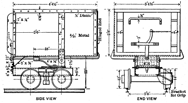
Tunnel Transportation.—The mining cars shown in Fig. 19 were of 1¼ cu. yd. capacity. The short wheel base and unbalanced loading caused a good many upsets, but they were compact, easily handled, and could be dumped from either side or end.
Muck Car (As Used in River Tunnels) Capacity 5,000 Lbs. or 1¼ Cu. Yd. Fig. 19. Click to view larger image.
The flat cars shown in Fig. 20 were of 3 tons capacity, and could hold two tunnel segments. As the working face was down grade from the shafts, the in-bound cars were run by gravity. For out-bound cars a cable haulage system was used, consisting of double-cylinder, Lidgerwood, single friction-drum, hoisting engines (No. 32) of 6 h.p., with cylinders 5 in. in diameter and 6 in. stroke and drums 10 in. in diameter. These were handily moved from point to point, but, as there was no tail rope, several men had to be used to pull the cable back to the face. After the second air-lock bulkhead walls had been built, a continuous-cable system, worked electrically, was put in each tunnel between the first and second air-locks.
The engine consisted of an electric motor driving a 3-ft. 6-in. drum hoist around which a ¾-in. steel wire cable passed three times. The cable was led around a sheave, down the tunnel on the right side of the in-bound track, and returned on the left side of the out-bound track. It was then carried around a set of sheaves, where a tension of 1,000 lb. was supplied by a suspended weight which acted on a sheave with a sliding axle on the tension carriage. The cable was supported throughout its length on 8-in. pulleys set in the floor at 50-ft. intervals. All the guide sheaves were 36 in. in diameter.
Flat Car for Tunnel Segments Capacity 6,000 lbs. Fig. 20. Click to view larger image.
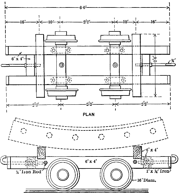
Each car was attached to the cable by a grip at its side. This was fastened and unfastened by hand, but was automatically released just before reaching the turn in the cable near each lock. This system could haul without difficulty an unbalanced load of 10 muck cars, spaced 100 ft. apart, up a 2% grade. The cable operated over about 1,000 ft. of tunnel, the motor being placed at the top of the grade. The driving motor was of the semi-armored, 8-pole, series-wound type, rated at 25 h.p., 635 rev. per min., and using direct current at 220 volts. The speed of handling the cars was limited by their having to pass through the air-locks on a single track. As many as 106 cars have been hauled each way in one 8-hour shift.
Disposal.—At Manhattan the tunnel muck was carried from the elevator over the upper level of the yard trestle and dumped into bins on the 33d Street side, whence it was teamed to the public dump at 30th Street and North River. At Weehawken the rock excavation was removed by the Erie Railroad on flat cars on which it was dumped by the tunnel contractor, but all the silt muck was teamed away to some marshy ground where dumping privileges were obtained.
The typical forces employed on transportation were as follows:
Receipt and Unloading of Material: Surface Transportation and Disposal.
At Manhattan Shaft, on 10-hour shifts:
2 Engineers on derricks. @ $3.00 per day.
2 Foremen. " 3.25 " "
15 Laborers loading and unloading iron. " 1.75 " "
7 Laborers on disposal. " 1.75 " "
6 Teams. " 7.50 " "
At Weehawken Shaft, on 10-hour shifts:
3 Engineers on derricks and locomotives. @ $3.00 per day.
16 Laborers loading and unloading iron. " 1.75 " "
3 Foremen. " 3.50 " "
11 Laborers on disposal. " 1.75 " "
6 Teams on disposal. " 6.50 " "
Tunnel Transportation (Including Shaft Elevator): Shaft elevators and to and from the first air-lock on 10-hour shift:
2 Engineers. @ $3.00 per day.
2 Signalmen. " 2.00 " "
1 Foreman. " 3.00 " "
12 Laborers. " 1.75 " "
Between first lock and working face, on 8-hour shifts, the force varied:
From 1 to 3 (average 2) Hoist engineers @ $3.00 per day.
From 0 to 2 (average 1) Lockman " 2.75 " "
From 1 to 2 (average 2) Trackmen " 3.00 " "
From 2 to 7 (average 4) Cablemen (pulling back cable) " 3.00 " "
Pumping.—The water was taken out of the invert by a 4-in. blow-pipe which was always kept up to a point near the shield and discharged into the sump near the shaft.
When the air pressure was removed and the blow-pipe device, consequently, was unavailable, small Cameron pumps, driven by compressed air, and having a capacity of about 140 gal. per hour, were used, one being set up wherever it was necessary to keep the invert dry; for example, at points where caulking was in progress.
Lighting.—The tunnels were lighted by electricity, the current being supplied, at a pressure of 250 volts, from the dynamos in the contractor's power-house.
Two 0000 wire cables were used as far as the second air-locks, about 1,650 ft. from the power-house, on each side; and beyond that point, to the junction of the shields (about 1,750 ft.), 00 and 0 wires were used. These cables also carried the current for the cable haulage system. Two rows of 16-c.p. lamps, provided with reflectors, were used in each tunnel; one row was along the side just above the axis, with the lights at about 30-ft. intervals; the other along the crown, with the lamps halfway between the side lamps, also at 30-ft. intervals. At points where work was in progress three groups of 5 lights each were used. The tunnels as a whole were well lighted, and in consequence work of all kinds was much helped.
Period No. 2.—Caulking and Grummettng.—November, 1906, to June, 1907.—After the metal lining had been built completely across the river in both tunnels, the work of making it water-tight was taken up. This consisted in caulking into the joints between the plates a mixture of sal-ammoniac and iron borings which set up into a hard rusty mass, and in taking out each bolt and placing around the shank under the washer at each end a grummet made of yarn soaked in red lead. These grummets were made by the contractor on the works, and consisted of three or four strands of twisted hemp yarn, known as "lath yarn," making up a rope-like cross-section about ¼ in. in diameter. Usually, one of these under each washer was enough, but in wet gravel, or where bolts were obliquely in the bolt-holes, two were used at each end. After pulling the grummets in, all the nuts were pulled up tight by wrenches about 3 ft. long, with two men on one wrench. Bolts were not passed as tight unless the nut resisted the weight of an average man on a 2½-ft. wrench.
Before putting in the caulking mixture, the joints were carefully scraped out with a special tool, cleaned with cotton waste, and washed with a stream of water. The usual mixture for sides and invert was about 2 lb. of sal-ammoniac and 1 lb. of sulphur to 250 lb. of iron filings or borings. In the arch, 4 lb. of sal-ammoniac and 3 lb. of sulphur to 125 lb. of filings was the mixture. A small hand-hammer was used to drive the caulking tool, but, in the sides and invert, air hammers were used with some advantage. The success of work of this kind depends entirely on the thoroughness with which the mixture is hammered in; and the inspection, which was of an exceedingly monotonous nature, called for the greatest care and watchfulness on the part of the Company's forces, especially in the pocket iron, where each bolt had to be removed, the caulking done at the bottom of the pockets put in, the bolts replaced; and the rest of the pockets filled. The results have been satisfactory, as the leakage under normal air and prior to placing the concrete averaged about 0.14 gal. per lin. ft. of tunnel per 24 hours, which is about 0.0035 gal. per lin. ft. of joint per 24 hours. With each linear foot of joint is included the leakage from 1.27 bolts. Afterward, when the concrete lining was in, the leakage was found to be about 0.05 to 0.06 gal. per lin. ft. of tunnel per 24 hours, which compares favorably with the records of other lined tunnels. The typical gang employed on this work was as follows:
In Pocket Iron:
1 General foreman @ $5.00 per day.
1 Mixer " 3.00 " "
1 Nipper " 3.00 " "
5 Caulkers " 3.00 " "
10 Grummeters " 3.00 " "
In Pocketless Iron:
1 General foreman @ $5.00 per day.
1 Mixer " 3.00 " "
1 Nipper " 3.00 " "
3 Caulkers " 3.00 " "
12 Grummeters " 3.00 " "
The average amount of caulking and grummeting done per shift with such a gang was (with pocketless grooves), 348 lin. ft. of joint and 445 bolts grummeted; and in pocket iron: 126 lin. ft. of joint and 160 bolts grummeted.
The caulking and grummeting work was finished in June, 1907, this completing the second period.
Period No. 3.—Experiments, Tests, and Observations.—April, 1907, to April, 1908.—The third period, that of tests and observations in connection with the question of foundations, is dealt with in another paper. It occupied from April, 1907, to November, 1908. The results of the information then gathered was that it was not thought advisable to go on with the foundations.
Period No. 4.—Capping Pile Bores, Sinking Sumps, and Building Cross-Passages.—April, 1908, to November, 1908.—In order to reduce the leakage from the bore segments to the least possible amount before placing the concrete lining, it was decided to remove the plugs and replace them with flat cover-plates; these have been described before, together with the filling of Bore Segments No. 2 with mortar to reduce the leakage around the distance piece.
During this period the turnbuckles to reinforce the broken plates were put in, and the sump sunk at the lowest point of the tunnel. These sumps have been described in a previous part of this paper; they were put down without trouble. As much as possible of the concrete lining was put in before the lining castings were taken into the tunnel, as the space inside was very restricted. The first lining casting was bolted to the flat flanges of the sump segment, the bolts holding the latter to the adjacent segments were removed, and the whole was forced down with two of the old shield jacks, taking a bearing on the tunnel. The two together exerted a pressure of about 150 tons. The plugs in the bottom of the sump segment were taken out, and pipes were put in, through which the silt squeezed up into the tunnel and relieved the pressure on the sump segment.
If the silt did not flow freely, a water-jet was used. The sump was kept plumb by regulating the jacks. In this way the sump was sunk, adding lining sections one by one, and finally putting on the top segment, which was composed of three pieces.
The time taken to sink one sump was about 4 days, working one 8-hour shift per day, and not counting the time taken to set up the jacks and bracing. The sinking of each section took from 4 to 6 hours. The air pressure was 25 lb. and the hydrostatic head 41 lb. per sq. in. The force was 1 assistant superintendent at $6.00 per day, 1 foreman at $4.50, and 6 laborers at $3.00 per day.
Cross-Passages.—It was during this period that the five cross-passages previously mentioned were built. In the case of those in the rock, careful excavation was needed so as to avoid breaking the iron lining. Drilling was done from both ends, the holes were closely spaced, and about 2 ft. 6 in. deep, and light charges of powder were used. The heading, 5 by 7 ft. in cross-section, was thus excavated in five lengths, with 24 holes to a length, and about 23 lin. ft. of hole per yard. About 5.3 lb. of powder per cu. yd. was used. The sides, top, and bottom were then drilled at a very sharp angle to the face and the excavation was trimmed to the right size. This widening out took about 7½ ft. of hole per cu. yd., and 0.9 lb. of powder.
In the passages in silt the excavation had to be 12 ft. wide and 13 ft. 8 in. high to give enough room inside the timbers. The plates at one end of the passage were first removed. An air pressure of 17 lb. was carried, which was enough to keep the silt from squeezing in and yet left it soft enough to be chopped with a spade.
A top heading, of full width and 6 ft. 8 in. high, was first taken out, and the roof was sheathed with 2-in. boards held by 10 by 10-in. head trees at 3-ft. centers, with 10 by 10-in. side trees. The lower 7 ft. of bench was then taken out, a tight floor of 6 by 6-in. cross-timber was put in, and also longer side trees, the head trees being temporarily held by two longitudinal 10 by 10-in. stringers blocked in place. The bulk of the space between the side trees was filled with 10 by 10-in. posts and blocking. The plates at the other end of the passage were then taken out from the other tunnel.
After the excavation was out, the outer reinforced concrete lining was built. Rough forms were used, as the interior surfaces of the passages were to be rendered with a water-proofing cement. A few grout pipes were built in, and all voids outside the concrete were grouted. Grouting was also done through the regular grout holes of the metal lining around the openings.
In the case of the most westerly of the cross-passages at Weehawken, which was in badly seamed rock carrying much water, a steel inter-lining, rather smaller than the concrete, was put in. The space between the concrete and the steel was left open, so that water coming through the concrete lining was stopped by the steel plate. This water was led back to the shield chamber in a special drain laid in the bench of the river tunnel and behind the ducts. From the shield chamber the water ran with the rest of the drainage from the Weehawken Land Tunnels to the Weehawken Shaft sump.
Typical Cross-sections Showing Successive Stages in Placing Concrete in River Tunnels Fig. 21. Click to view larger image.
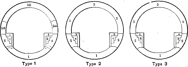
Period No. 5.—Placing the Concrete Lining.—November, 1908, to June, 1909.—During the fifth period the concrete lining was put in. This lining was placed in stages, as follows: First, the invert; second, the duct bench; third, the arch; fourth, the ducts; and fifth, the face of the bench. This division can be seen by reference to Fig. 21.
All the work was started on the landward ends and carried toward the middle of the river from both sides. Except where the Weehawken force passed the lowest point of the tunnel, which is at Station 241 or nearly 900 ft. to the west of the middle of the river, all the work was down grade.
Before any concrete was placed, the surface of the iron was cleaned with scrapers and wire brushes, and washed with water. Any leaks in the caulking and grummeting (finished by June, 1907, and therefore all more than 12 months old) were repaired. All the grout hole plugs were examined, and the plugs in any leaking ones were taken out, smeared with red lead, and replaced. The leakage in the caulking was due to the fact that the tunnel had been settling slightly during the whole 12 months of pile tests, and, therefore, had opened some of the joints. After the caulking had been repaired and the surface thoroughly cleaned, the flanges were covered with neat cement (put on dry or poured on in the form of thick grout) just before the concrete was placed.
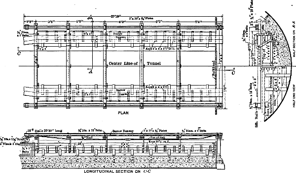
Invert Concrete.—The form used for the landward type of concrete, that is, the one with a middle drain, consisted of a frame made of a pair of trussed steel rails on each side of the tunnel and connected at intervals with 6 by 6-in. cross-timbers; two "wing forms" were hung from this frame by adjustable arms. These wings formed the curved sides of the invert, the lip, and the form for the middle drain. The whole form was supported on three wheels, two on the rear end running on a rail laid on the finished concrete, and the third in front attached to the frame by a carriage and running on a rail temporarily laid on the iron lining. The form was braced from the iron lining by 6 by 6-in. blocks.
For the soft-ground type of invert, namely, the one without the middle drain, a form of the same general type was used, except that the form for the middle drain was removed. After the form had been in use for some time, "key pieces" (made of strips of wood about 1 ft. 3 in. in length and 3 by 3 in. in cross-section) were nailed circumferentially on the under side of the wings at 2-ft. intervals. This was done because, at the time, it was not known whether ballasted tracks or some form of rigid concrete track construction would be adopted, and, if the latter, it was desirable not to have the surface smooth.
The concrete was received in cars at the rear end of the form and dumped on a temporary platform. It was then loaded into wheel-barrows on the runways, as shown in Fig. 22. The concrete was thrown from the barrows into the invert, where it was spaded and tamped.
In cases where there was steel-rod reinforcement, the concrete was first brought up to the level of the underside of these rods, which came between the wings; the rods were laid in place, and then more concrete was placed over the rods and brought up to the level of the bottom of the wings. Where there was no reinforcement, the concrete was brought up in one lift.
Concrete Form Standard in River Tunnels Fig. 22. Click to view larger image.
After this was finished, the concrete behind the wings was placed, thoroughly spaded and tamped, and, where there were longitudinal reinforcing rods, these were put in at their proper level. Where there were circumferential rods, the 16-ft. rods had already been put in when the lower part of the concrete was placed. As the invert was being finished off, the 8-ft. rods were embedded and tied in position.
The longitudinal rods were held in place at the leading end of each length of arch by the wooden bulkhead, through which holes were drilled in the proper position. At the rear end they were tied to the rods projecting from the previous length. The quantity of water used in mixing the invert concrete needed very nice adjustment; if too wet, the middle would bulge and rise when the weight of the sides came on it; and, if too dry, it would not pack properly between the flanges of the iron lining. The difficulties as to this were often increased by the flow of accumulated leakage water from the tunnel behind on the concrete while it was being put in. To prevent this, a temporary dam of sand bags was always built across the last length of finished invert concrete before beginning a new length. A sump hole, about 4 by 1 ft. and 1 ft. deep, was left every 800 ft. along the tunnel, and a small Cameron pump was put there to pump out the water.
The invert forms were left in place about 12 hours after the pour was finished. The average time taken to fill a length of 30 feet was 7 hours, the form was then left 12 hours, and it took 2 hours to set it up anew. The total time for one length, therefore, was 21 hours, equal to 34 ft. per 24 hours. At one place, a 45-ft. form was used, and this gave an average speed of 45 ft. per 24 hours.
An attempt was made to build the invert concrete without forms (seeing that a rough finish was desired, as previously explained, to form a key for possible sub-track concrete), but it proved a failure.
The typical working force (excluding transport) was as follows:
1 Foreman @ $3.25 per shift.
2 Spaders " 2.00 " "
9 Laborers " 1.75 " "
The average time taken to lay a 30-ft. length of invert was 7 hours; the two spaders remained one hour extra, smoothing off the surface.
For setting the form, the force was:
1 Foreman @ $4.50 per shift.
5 Carpenters " 3.25 " "
6 Carpenters' helpers " 2.25 " "
The average time taken to erect a form was 2 hours, 1 carpenter and 1 helper remaining until the concrete was finished.
Duct Bench Concrete.—The duct bench (as described previously) is the portion of the concrete on which the ducts are laid. The exact height of the steps was found by trial, so as to bring the top of the ducts into the proper position with regard to the top and the face of the bench.
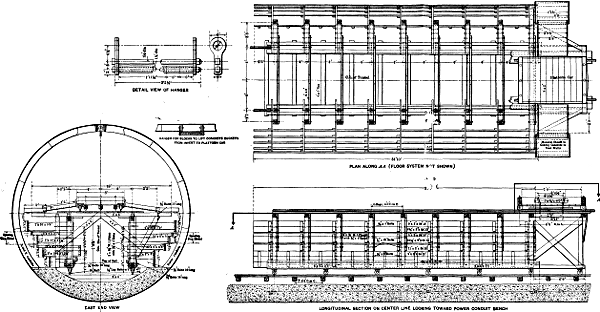
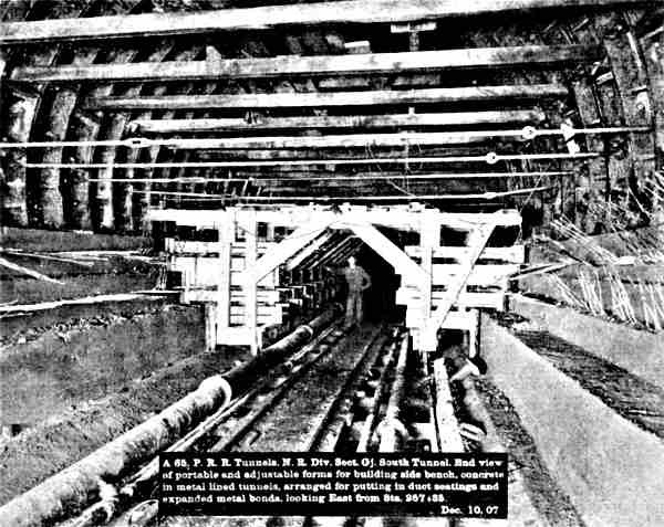
Both kinds of duct bench forms were of the same general type. A drawing of one of them is shown on Plate XLII. The form consisted of a skeleton framework running on wheels on a track at the level of the temporary transportation tracks. The vertical faces of the steps were formed by boards supported from the uprights by adjustable arms. The horizontal surfaces were formed by leveling off the concrete with a shovel at the top of the vertical boards. Where the sheets of expanded metal used for bonding came at a step, the lower edge of the boards forming the back of the step was placed 1 in. above the one forming the front of it; but, when the expanded metal came in the middle of a step, a slot 1 in. wide was left at that point to accommodate it.
A platform was formed on the top of the framework for the form, and on this a car forming a sort of traveling stage was run. There was ample room to maintain traffic on a single track through the form. A photograph of the form is shown in Fig. 1, Plate XLIII.
The concrete, for the most part, was received at the form in ¾-cu. yd. dumping buckets. The buckets were lifted by the rope from a small hoisting engine. This rope passed over a pulley attached to the crown of the tunnel and dumped into the traveling stage on the top of the form. In this the concrete was moved along to the point where it was to be deposited, and there it was thrown out by shovels into the form below. For a portion of the period, while the duct bench concrete was being laid, it was not necessary to maintain a track for traffic through the form and, during that period, the concrete for the lower step was placed from below the form, the concrete being first dumped on a temporary stage at the lower track level.
Owing to the horizontal faces of the steps being uncovered, there was a tendency for the concrete there to rise when concrete was placed in the steps above. For this part of the work, also, it was necessary to see that the concrete was not mixed too wet, for, when that was the case, the concrete in the upper steps was very apt to flow out at the top of the lower one. At the same time, there was the standing objection to the mixture being too dry, namely, the responsibility of getting a sufficient amount of spading and tamping done. Particulars of the exact quantity of water used are given later in describing "Mixing." Fig. 2, Plate XLIII, illustrates the process of laying.
PLATE XLII. TRANS. AM. SOC. CIV. ENGRS. VOL. LXVIII, No. 1155. HEWETT AND BROWN ON PENNSYLVANIA R. R. TUNNELS: NORTH RIVER TUNNELS.
Duct-bench Concrete Form in River Tunnels Click to view larger image.
In the section of the tunnel in which there were circumferential reinforcement rods in the duct bench, the rods were in place before the laying commenced, as they had been placed with the invert concrete. The circumferential reinforcing rods in the arch came down into the upper part of the duct bench concrete; these rods were put in position and tied to the iron lining in the crown at the same time as the duct bench concrete was being finished off. Openings for the manholes were left in the duct bench at the regular stationing.
The average time taken to fill a length of 35 ft. was about 6 hours; the form was then left in position for about 8 hours—usually enough to let the concrete set properly—and then moved ahead; it then took about 3 hours to set it up again ready to continue work. The total time for a length, therefore, was about 17 hours, equal to an average progress of about 49 ft. per day. The average force engaged in duct bench concrete (not including transport) was:
1 Foreman @ $3.25 per day.
2 Spaders " 2.00 " "
9 Laborers " 1.75 " "
Arch Concrete.—By far the greater part of the arch work was put in with traveling centers before the face of the bench was built, in which case the whole of the arch was built at once. A short length of arch at each end of the tunnel was built after the face of the bench, in which case the haunches or lower 5 ft. were laid first and the upper part of the arch later.
The first traveling centers were used on the New York side, and were 50 ft. long. The laggings were of 4-in. yellow pine, built up in panels 10 ft. long and 16 in. wide for the sides, and solely longitudinal lagging 5 ft. long for the key.
It was pretty certain that the results to be obtained from forms of such a length would not be satisfactory, and this was pointed out to the contractor, who, however, obtained permission to use them on trial. Grout pipes were built in, as it was not likely that the concrete could be packed tightly into the upper part of the lining.
After about 300 lin. ft. of arch had been built with these forms, a test hole was cut out and large voids were found, and, to confirm this, another hole was cut, and similar conditions observed.
The results were so unsatisfactory that orders were given that the use of longitudinal key lagging should be discontinued, and cross or block lagging used instead. These block laggings were 6 in. in length (in the direction of the tunnel) and 2 ft. in width; at the same time, the system of grout pipes was changed. This will be described later under "Grouting." It was soon found that with block lagging a better job could be made of packing the concrete up into the keys, but the time taken to "key up" a 50-ft. length was so great that the rest of the arch had set by the time the key was finished. Despite a lot of practice, this was the case, even in the unreinforced type. When the reinforcing rods were met, the time for keying up became still greater, and therefore the contractor was directed to shorten the forms to 20-ft. lengths. A typical working force for a 50-ft. length was:
1 Foreman @ $3.25 per day.
4 Spaders " 2.00 " "
12 Laborers " 1.75 " "
Details of the 20-ft. forms are shown on Plate XLIV. The lower 4 ft. of lagging was built on swinging arms, which could be loosened to allow the centers to be dropped and moved ahead. The rest of the lagging was built up in panels 10 ft. long and 1 ft. 4 in. high. The ribs rested on a longitudinal timber on each side; these were blocked up from the top step of the duct bench concrete. When the form was set, or when it was released, it was moved ahead on rollers placed under it.
The concrete was received at the form in ¾-cu. yd. dumping buckets; from the flat cars on which they were run, these were hoisted to the level of the lower platform of the arch form. At this level the concrete was dumped on a traveling car or stage, and moved in that to the point on the form where it was to be placed. For the lower part of the arch, the concrete was thrown directly into the form from this traveling stage, but, for the upper part, it was first thrown on the upper platform of the arch. The hoisting was done by a small Lidgerwood compressed-air hoister, and set up on an overhead platform across the tunnel. The pulley over which the cable from the hoister passed was attached to the iron lining near one end of the form, and the traveling stage ran back from the arch form on a trailer, shown on Plate XLIV. When it was impossible to hang a pulley—owing to the concrete arch having been built at the point where the trailer stood—an A-frame was built on the trailer, and the pulley was attached to that.
PLATE XLIII. TRANS. AM. SOC. CIV. ENGRS. VOL. LXVIII, No. 1155. HEWETT AND BROWN ON PENNSYLVANIA R. R. TUNNELS: NORTH RIVER TUNNELS.
Fig. 1. Click to view larger image. Fig. 2. Click to view larger image.
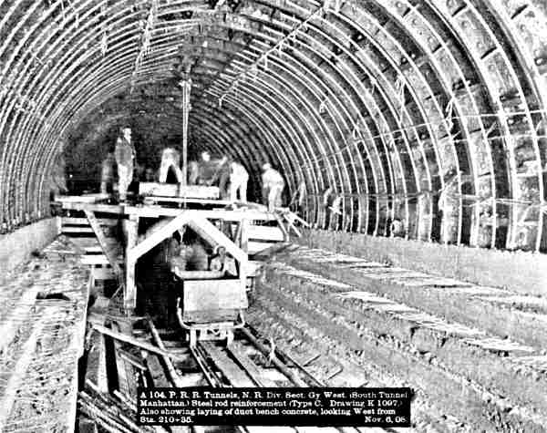
In laying the lower part of the arch, about 1 ft. of lagging (including the swinging arms) was first set, the other panels being pulled up toward the top of the arch. When that was filled, the next panel above was lowered into place, and the work continued. As the concrete rose toward the key, it was packed up to a radial surface, so that the arch would not be unduly weakened if the sides set before the key was placed. All the time, great care was taken to see that the concrete was carefully packed into the segments of the metal lining. The quantity of water used in the concrete was carefully regulated, more being used in the lower than in the upper parts of the arch.
In places where there were no reinforcing rods, the width of the concrete key was the length of the block lagging, namely, 2 ft. Where there was circumferential reinforcement, the key had to be more than 5 ft. wide, in order to take the 5-ft. closure rods used in the key. This naturally increased the time of keying very much. On the places where the 5-ft. longitudinal laggings were used, it was impossible to fill the flanges of the metal lining much higher than their undersides.
As the concrete used in the key had to be much drier than that used elsewhere, it was not easy to get a good surface. This trouble was overcome by putting a thin layer of mortar on the laggings just before the concrete was put in.
The overhead conductor pockets were a great hindrance to the placing of the key concrete, especially where the iron was below true grade. Whenever an especially troublesome one was met, a special grout pipe was put in to fill up unavoidable holes by grouting after the concrete had set. All the circumferential reinforcing rods were bent in the tunnel by bending them around a curved form of less diameter than the required bend. This generally left them all right in the middle of their length, but with their end portions too straight; in such cases the ends were bent again. All rods were compared with a template before being passed for use.
The arch forms were left up for 48 hours after keying was finished. Levels taken after striking the forms showed that no appreciable settlement occurred. An average gang for a 20-ft. length of arch was:
1 Foreman @ $3.25 per shift.
2 Spaders " 2.00 " "
10 Laborers " 1.75 " "
Table 30 shows the progress attained under various conditions.
Whenever the face of the bench concrete was constructed before the arch, the latter was built in two separate portions, that is, the bottom 5 ft., or "haunches" of the arch, as they were termed, were built on each side and the rest of the arch later. This involved the use of two separate sets of forms, namely, for the haunch and for the arch. Not very much arch was built in this way, and, as the methods were in principle precisely the same as those used when all the arch was built in one operation, no detailed description is needed.
No provision was made in the contract for grouting the concrete arch, but it soon became evident that by ordinary methods the top part of the concrete could not be packed solid against the iron segments, especially in the keys. As it was imperative to have the arch perfectly solid, it was determined to fill these unavoidable gaps with a 1:1 Portland cement grout, at the same time making every effort to reduce the spaces to a minimum. This made it necessary to build grout pipes into the concrete as it was put in.
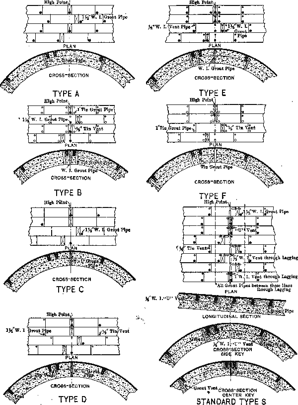
The first type of grout pipe arrangement is shown as Type A, in Fig. 23. This was used with the longitudinal key laggings; when this method was found to be no good, and cross-laggings were used, the system shown as Type B, in Fig. 23, was adopted, in which vents were provided to let out the air during grouting. The expense of these pipes was high, and the contractor obtained permission to use sheet-iron tubes, which, however, were found to be unsuitable, so that the screwed pipes were used again. The contractor next obtained permission to try dispensing altogether with the vent pipes, and so Type C, in Fig. 23 was evolved. This, of course, was found to be worse than any of the other systems, as the imprisoned air made it impossible to force grout in. Several other modifications were made, and are shown in Fig. 23.
It was then decided to devise as perfect a system as possible, without allowing the question of cost to be the ruling factor, and to use that system throughout. In this system, shown as Type S, in Fig. 23, most of the vent pipes were contained in the concrete, and their size was independent of the thickness of the arch, so that they were easily fixed in position and not subject to disturbance while placing the concrete. This system was used for about 80% of the total length of the tunnel, and proved entirely satisfactory. The machine used for grouting was the same as that used for grouting outside the metal lining.
PLATE XLIV. TRANS. AM. SOC. CIV. ENGRS. VOL. LXVIII, No. 1155. HEWETT AND BROWN ON PENNSYLVANIA R. R. TUNNELS: NORTH RIVER TUNNELS.
Details of 20 foot Movable Form and Traveler Click to view larger image.
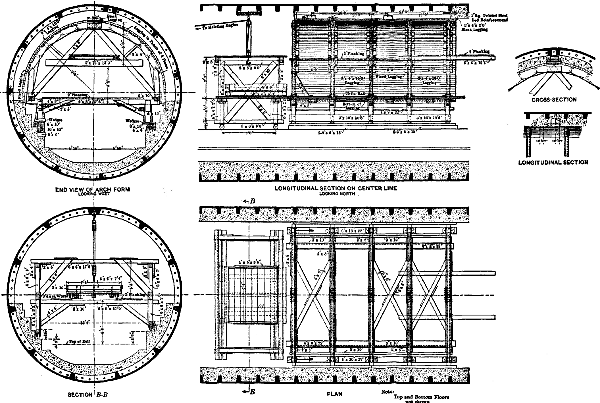
TABLE 30.— Average Time Taken for Various Operations Connected with Building Concrete Arches in Subaqueous Tunnels.
Average time in hours, form stood after filing. Type of reinforcement. Length of section, in feet. Time, in hours, moving and erecting forms. Time, in hours, placing concrete in Arch. Time, in hours, placing concrete in key. Time, in hours, placing concrete in key and arch. Total Time in hours, for moving, erecting, and filling. Total time in hours, per linear foot, for moving, erecting, and filling. Remarks.
70 A day work 50 20 15 15.40 30.40 50.40 1.01
Moving Erecting
A day work 20 2 3 8.30 2.40 11.10 16.10 0.80
53 B day work 20 2 3 10.40 11.20 22.10 27.00 1.35 Includes placing rods
58 C day work 20 2 3 11.00 7.20 18.20 23.20 1.16 do.
58 D day work 20 2 3 9.30 4.35 14.25 19.25 0.91 do.
53 D day work 20 2 3 6.15 2.05 8.20 13.20 0.05 do.
53 Sub-Type No. 1 piece work 20 2 3 6.00 3.00 9.00 14.00 0.70 do.
Fig. 23. Click to view larger image.
The only compressed air available was the high-pressure supply, at about 90 lb.; a reducing valve, to lower this pressure to 30 lb. was used between the air line and the grouting machine. This was thought to be about as high a pressure as the green concrete arch would stand, and, even as it was, at one point a section about 2 ft. by 1 ft. was blown out.
A rough traveling stage resting on the bottom step of the duct bench concrete was used as a working platform. In the earlier stages of the work the grouting was carried on in a rather haphazard manner, but, when the last system of grout and vent pipes was adopted; the work was undertaken systematically, and was carried out as follows:
Two 20-ft. lengths of arch were grouted at one time, and, in order to prevent the grout from flowing along the arch and blocking the pipes in the next lengths, a bulkhead of plaster was made at the end of every second length to confine the grout.
After a section had been grouted, test holes were drilled every 50 ft. along the crown to see that all the voids were filled; if not, holes were drilled in the arch, both for grouting and for vents, and the faulty section was re-grouted. An average of ¾ bbl. of cement and an equal quantity of sand was used per linear foot of tunnel. The average amount put in by one machine per shift was 15 bbl., and therefore the average length of tunnel grouted per machine per shift was 20 ft. The typical working force was:
1 Foreman @ $3.75 per shift
1 Laborer running grout machine " 2.00 " "
2 Laborers handling cement and sand. " 1.75 " "
1 Laborer tending valve and grout pipes " 1.75 " "
After the grouting was finished, the arches were rubbed over with wire brushes to take off discoloration, and rough places at the junctions of adjoining lengths or left by the block laggings were bush-hammered.
Face of Bench Concrete.—The form used for this portion of the work is shown on Plate XLV. It consisted of a central framework traveling on wheels, and, from the framework, two vertical forms were suspended, one on each side, and equal in height to the whole height of the bench. Adjusting screws were fitted at intervals both at top and bottom, and thus the position of the face forms could be adjusted accurately. The face forms were built very carefully of 3-in. tongued and grooved yellow pine, and one 50-ft. form was used for 3,000 ft. of tunnel without having the face renewed. Great care was taken to set these forms true to line and grade, as the appearance of the tunnel would have been ruined by any irregularity. Joints between successive lengths were finished with a V-groove.
The concrete was received at the form in dumping buckets; these were hoisted to the top of the form by a Lidgerwood hoister fixed to a trailer. The concrete was placed in the form by shoveling it from the traveling stage down chutes fitted to its side. The quantity of water to be used in the mixture needed careful regulation. The first few batches in the bottom had to be very wet, and were made with less stone than the upper portion, in order that the concrete would pack solidly around the niche box forms and other awkward corners.
The forms for the ladders and refuge niches were fastened to the face of the bench forms by bolts which could be loosened before the main form was moved ahead, and in this way the ladder and niche forms were left in position for some time after the main form was removed.
At first the forms were kept in place for 36 hours after finishing a length, but, after a little experience, 24 hours was found to be enough. In the summer, when the rise of temperature quickened the set, the time was brought down to 18 hours. The average time taken for a 50-ft. length was:
Laying concrete 4½ hours.
Interval for setting 18 "
Moving forms ahead and resetting 5 "
———
Total 27½ hours.
The typical working gang was:
Laying Concrete.
1 Foreman @ $3.25 per shift.
2 Spaders " 2.00 " "
8 Laborers " 1.75 " "
TRANS. AM. SOC. CIV. ENGRS. VOL. LXVIII, No. 1155. HEWETT AND BROWN ON PENNSYLVANIA R. R. TUNNELS: NORTH RIVER TUNNELS.
Traveling Concrete Form for Face of Bench Wall as Used in River Tunnels Click to view larger image.
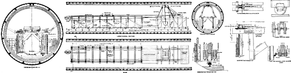
Moving and Setting Forms.
1 Foreman @ $4.00 per shift.
10 Laborers @ 1.75 per shift.
After the forms were removed, any rough places at the lower edge, where the concrete joins the "lip," were bush-hammered; no other cleaning work was done.
Duct Laying and Rodding.—The design and location of the ducts have already been described. It will have been seen that the duct-bench concrete was laid in steps, on which the ducts were laid, hence the maintenance of the grade and line in the ducts was an easy matter. The only complication was the expanded metal bonds, which were bent up out of the way of the arch forms and straightened out again after the arch forms had passed. The materials, such as ducts, sand, and cement, were brought into the tunnel by the regular transportation gang. The mortar was mixed in a wooden trough about 10 ft. long, 2 ft. 6 in. wide and 8 in. deep.
After the single-way ducts had been laid, all the joints were plastered with mortar, in order to prevent any foreign substance from entering the ducts. This was not necessary with the multiple duct, as the joints were wrapped with cotton duck. The ducts were laid on a laying mandrel, and, as soon as possible after the concrete was laid around a set of ducts, they were "rodded" with a rodding mandrel. Not many obstructions were met, and these were usually some stray laying mandrel which had been left in by mistake, or collections of mortar where the plastering of the single-way joints had been defective.
In the 657,000 duct ft. of conduit in the river tunnels only eight serious obstructions were met. That the work was of exceptionally high quality is shown by the fact that a heavy 3-in. lead cable has been passed through from manhole to manhole (450 ft.) in 6 min., and the company, engaged to lay the cables in these ducts, broke all its previous records for laying, not only for tunnel work, but also in the open.
Fig. 1, Plate XXXV, shows a collection of the tools and arrangements used in laying and rodding ducts. The typical working force was:
Laying Multiple Ducts.
1 Foreman @ $3.50 per shift.
9 Laborers " 1.75 " "
Laying Single-Way Ducts.
1 Foreman @ $3.50 per shift.
8 Laborers " 1.75 " "
Rodding Multiple Ducts.
1 Foreman @ $3.50 per shift.
5 Laborers " 1.75 " "
Rodding Single-Way Ducts.
1 Foreman @ $3.50 per shift.
5 Laborers " 1.75 " "
The average progress per 10-hour shift with such gangs was:
Laying multiple ducts 4,000 duct ft.
Laying single-way ducts 1,745 " "
Rodding multiple ducts 4,040 " "
Rodding single-way ducts 2,532 " "
No detailed description need be given of the concreting of the cross-passages, pump chambers, sumps, and other small details, the design of which has been previously shown. The concrete was finished on June 1st, 1909.
Period No. 6.—Final Cleaning Up.—June, 1909, to November, 1909.—As soon as all the concrete was finished, the work of cleaning up the invert was begun. A large quantity of débris littered the tunnels, and it was economical to remove it as quickly as possible. The remaining forms were first removed, and hoisting engines, supported on cross-timber laid across the benches, were set up in the middle of the tunnel at about 500-ft. intervals.
Work was carried on day and night, and about 169 ft. of single tunnel was cleared per 10-hour shift. Work was begun on May 28th, and finished on July 15th, 1909. For part of the time it was carried on at two points in each tunnel, working toward the two shafts, but when the work in the Weehawken Shaft, which was being done at the same time, blocked egress from that point, all material was sent out by the Manhattan Shaft.