Introductory material (continued 3)
Reading edition
20. Q. How should the lubricator be filled?
A. First close all valves connected with the lubricator, open drain plug and remove filling plug, allowing water to escape until oil appears with it. Drain plug should then be closed. Fill the oil tank in the usual way, being careful not to overflow it; then replace filling plug. If the supply of oil is insufficient to fill the lubricator, water can be used to finish it, as the lubricator will begin feeding sooner when filled full.
21. Q. After filling lubricator, what should be done?
A. Open the steam throttle to the lubricator wide, then carefully open the water valve, but do not open the feeds until sure the chamber in the glass is filled with water.
22. Q. How long before leaving terminal should the feed valves be opened? Why?
A. About fifteen minutes; this time is necessary to allow oil to feed through the oil pipe and reach the steam chests.
23. Q. How many drops should be fed per minute?
A. From one to seven, timed by the watch, depending on conditions. Cylinders of large size require more oil than smaller ones.
24. Q. If lubricator feeds regularly when working steam and too rapidly after shutting off, what is the trouble?
A. The opening in the choke plug at the lubricator or through the steam valves at the steam chest is too large and should be reduced to the proper size by applying new chokes or valves.
25. Q. When valves appear dry while using steam and the lubricator is working all right, what would you do to relieve these conditions?
A. Ease off throttle for a few seconds to reduce the steam chest pressure and drop the reverse lever a few notches to give the valve a longer travel; oil held in the pipes will then flow down.
FEDERAL REGULATIONS
For Inspection of Locomotive Boilers and Safety Appliances
1. Q. What is the purpose of the federal rules and regulations for inspection of locomotive boilers?
A. So that all railroads operating under the laws of the United States government, would be obliged to maintain their boilers in a safe working condition.
2. Q. What is the purpose of the quarterly and monthly interstate inspection cards placed in the cab of the locomotive?
A. So that the federal inspector or engineer may see that the locomotive boiler has received its monthly or quarterly inspection.
3. Q. What constitutes a safety appliance, as applied to a locomotive?
A. Any appliance that is placed on a locomotive for the purpose of protecting the employees from personal injury.
4. Q. Name some of the safety appliances found on a locomotive?
A. Shield for tubular glass lubricators, also shields for water glass, automatic couplers, with lever attachments, air brakes, etc.
5. Q. In what condition should safety appliances be maintained?
A. They should be maintained in first class condition.
6. Q. What should be done in event of any of the safety appliances being damaged while engine is in service so as to render it unsafe?
A. Warn all employees whose duties require them to work around the locomotive of its unsafe condition, then make report to those in authority so that it may be taken out of service until repairs are made.
7. Q. What effort should be made on the part of the engineer to prevent persons using a safety appliance which he knows is damaged and unsafe?
A. He should use such precaution as in his judgment would protect from injury all persons who are on or around the locomotive.
8. Q. What is the duty of the engineer in event of his discovering a safety appliance which is in an unsafe condition when taking an engine from roundhouse territory?
A. He should report at once to the person in authority so that necessary repairs may be made before engine goes into service.
PYLE-NATIONAL ELECTRIC HEADLIGHT
1. Q. Why are electric headlights applied to locomotives?
A. Electric headlights are applied to locomotives so that the engineer may have a clear view of the track for enough ahead of the train to enable him to protect the company's property in his charge.
2. Q. How far ahead of the engine should the arc headlight illuminate the track?
A. Not less than from fifteen to twenty telegraph poles.
3. Q. State how you would focus the lamp.
A. First, would adjust back of the reflector so front edge of reflector will be parallel with front edge of case. Second, adjust the lamp to have point of copper electrode as near the center of reflector as possible with carbons as near the center of the chimney holes as you can set them. Third, have the locomotive on straight track. Now move the base of the lamp around until you get a parallel beam of white light straight down the center of the track, then tighten the lamp down.
4. Q. If the light throws shadows upon the track, is it properly focused?
A. No.
5. Q. If the light is properly focused, that is, if the rays are leaving the reflector in parallel lines, but the light does not strike the center of the track, what should be done?
A. When the light rays are thrown out in parallel lines and they do not strike the center of the track, it denotes that the headlight case is not set straight with the engine, and the entire case on base board must be shifted until the shaft of light strikes the track as desired.
6. Q. What can you do to insure a good and unfailing light for the entire trip?
A. By carefully inspecting the entire equipment before departing on each trip, and know that there are no wires with insulation charred or worn off, that all screws and connections are tight, commutator clean and brushes set in brush holder in proper manner. Carbon in lamp of sufficient length to complete trip, and that the carbon will feed through the clutch freely and rests central over the copper electrode. Copper electrode cleaned off, oil in both bearings and see that steam does not blow at stuffing box gland.
7. Q. What kind of oil and how much would you use in the bearings of the electric headlight equipment?
A. Would use the best grade of black or engine oil furnished for both bearings and only enough oil in oil cellar that the revolving loose oil ring may trail through the oil. When bearings are supplied with oil cups, use a heavy oil such as good engine or valve oil.
8. Q. Why should you not use valve oil in these bearings?
A. Valve oil cannot be used successfully in the main bearing because of its heavy body. Valve oil could not be carried up to shaft by the oil ring in cold weather, as the ring will not revolve.
9. Q. What is the most vital part of the dynamo?
A. The commutator.
10. Q. What care or attention should be given the commutator?
A. The commutator must be kept clean, free from dirt, and the mica must be kept filed a trifle below the surface of the copper bars.
11. Q. What kind of a bearing should the brush have on the commutator?
A. Brushes should be fitted to have a bearing with the same contour as the commutator.
12. Q. How are the brushes fitted?
A. Brushes are fitted by cutting a strip of No. 0 sandpaper about the width of the commutator surface (have the dynamo idle), place the strips of sandpaper under the brush, then pull the sandpaper from left to right; continue this process until the brush has been fitted to a true smooth bearing. Then trim about one-eighth inch off of the front edge of the brush.
13. Q. Is it advisable to ever try to fit a brush with a file or knife?
A. Most emphatically no. You could not get a bearing across the brush no matter how hard you might try with either a file or a knife.
14. Q. Why is it important to clean the scale off of the point of the copper electrode each trip?
A. The scale on the copper electrode after it has cooled off is a non-conductor of current, and acts as a blind gasket between the carbon and the copper electrode. Unless this scale is removed, the current cannot pass between the points of carbon and electrode and you cannot, therefore, have a light. When the dynamo fields are compound wound, it is unnecessary to clean scale from copper electrode oftener than once a week, at which time copper electrode should be removed from holder and all scale cleaned off. (With compound wound dynamo fields the cab lamps will continue to burn when head-lamp is extinguished by lifting carbon by hand.)
15. Q. How should the copper electrode be trimmed at the point?
A. The copper electrode should have about one-eighth inch surface on the contact point.
16. Q. How far should the copper electrode project over the holder?
A. About one inch.
17. Q. Should the electrode be raised up to one and one-half inches, what might happen?
A. If the copper electrode was run at a point so near the clutch, the intense heat of the arc might do damage to the top carbon holder and clutch.
18. Q. What regulation should be given to the tension spring No. 93 of the lamp, and why?
A. This tension spring, No. 93, should be regulated when the current is off the lamp and should be adjusted only tight enough to pull the magnet yoke up against the top stop lug on the side of lamp column.
19. Q. If this tension spring was tightened too tightly, what might happen?
A. At usual speed between stations, the movement of the engine would impart an added resistance against the pull of the solenoid by the tension spring, which would shorten up the arc and dim down the light.
20. Q. Is there anything else that could cause the light to dim down when the engine is running fast?
A. Yes; if the spring No. 92-A that hold the heel of the clutch should be too weak, the heel of the clutch would be forced up by the motion of the locomotive; this would release the carbon which would fall to the point of the copper electrode, causing the light to dim down, or, if the clutch should be used until the sharp edge that grips the carbon should have become worn smooth or round, the same would occur.
21. Q. If the light burns satisfactorily while the engine is in motion, but goes out when engine is stopped, where would you find the trouble?
A. This trouble is most always found to be caused by the tension spring No. 93 being too weak, though if the dash-pot plunger has become corroded until it sticks in the dash-pot, the light will act the same as if the tension spring were too weak.
22. Q. If the dash-pot should be found stuck, would you put oil in it?
A. Coal oil could be used to clean and cut the dirt out of the pot and from off the plunger, but after the dash-pot and plunger have been cleaned, all oil must be wiped off, for oil would cause the plunger to stick as well as collect dirt.
23. Q. If the carbon of lamp should "jig or pound", what can be done to stop it?
A. If the carbons pound the electrode, it is evidence that the iron armature No. 64 may be too far out of the solenoid, or the speed of the turbine engine may be too slow. This trouble can be remedied by adding another link to the suspension link, which has one end connected to the magnet yoke, the other end being connected to the iron armature No. 64. If, however, when the arc is formed, it is found that the bottom end of iron armature No. 64 measures one-half inch from bottom of solenoid, the pounding is caused by the speed of turbine engine being too slow.
24. Q. If the copper electrode was fusing, how would you know it?
A. When the copper electrode is fused, a green light is always given off.
25. Q. What should be done when a green light is seen?
A. Immediately close off on the steam throttle until a white light re-appears.
26. Q. What is the cause of the fusing of the copper electrode?
A. Usually too high speed of the armature, although should you connect the wires up wrong that the current flowing from the dynamo to the lamp should enter the lamp at the electrode instead of passing through the carbon first, you would get a green light and fuse the electrode.
27. Q. What arrangements have been made so that you cannot connect the wires wrong?
A. The positive binding posts, both at the dynamo and the lamp, have been provided with a much larger hole to receive the wire than has been made in the negative binding posts, and the ends of the positive wire should always be bent or doubled back, so that they will just enter the receptacle in the positive binding posts, but cannot be connected at the negative binding posts.
28. Q. Should the copper electrode and holder become fused until no longer serviceable while on the road, what would you do?
A. Would remove the damaged holder from the lamp and substitute either an iron bolt of sufficient length or a carbon, securing the improvised electrode in the bracket of lamp same as the electrode holder is held, only being sure that the end of the bolt or carbon comes up into the center of the reflector and did not rest on the base of reflector or lamp.
29. Q. What is the difference between a series wound equipment and a compound wound equipment, and what advantages are obtained from the use of the compound equipment.
A. With the series wound equipment, the incandescent cab lights burn only with the arc lamp, while with the compound machine the incandescent lamps are independent of the arc and can be used as desired.
30. Q. If you were running along with your light burning steadily and nicely, then suddenly the light began to flash badly and kept it up, where would you look for the trouble?
A. Trouble would usually be found at one of the binding posts, where one of the binding post screws would be found loose.
31. Q. If you were running along with light burning satisfactorily and suddenly it went out, where would you be likely to find the trouble?
A. You would find that either the carbon had burned out, one of the lead wires had broken between the dynamo and the lamp, or one of the wires had gotten loose at the binding post and fallen out.
32. Q. If the light goes out while you are between stations, what course should an engineer pursue?
A. If the light goes out while you are between stations and an investigation cannot be made within a few minutes thereafter to determine the cause, the steam should be shut off from the turbine and the dynamo stopped until such time when the cause of failure can be determined.
33. Q. Why is it essential to shut off steam and stop the equipment?
A. For the reason that if the failure was due to a short circuit, damage might be done to the coils or armature by overheating.
34. Q. How does the equipment act when short-circuited?
A. When there is short circuit, the engine will labor heavily, run slow with a large volume of steam blowing at the exhaust, there will be no light shown either at the arc or cab lamps, and the carbon point and cab lights will only show a dull red or go entirely out.
35. Q. How will the equipment act when the circuit is broken, either by a broken disconnected wire or a burned-out carbon?
A. With a broken circuit the engine will run noiselessly and fast with very little steam blowing at exhaust and no light will be seen at the arc or on cab lights.
36. Q. If the insulation on the cab wires is worn off until your two wires can come together either directly or through the medium of some metallic substance, what would occur?
A. A short circuit would result that would put out all of your lights.
37. Q. What should be done?
A. Wrap the exposed wire, if you can locate it, with a piece of waste, or if you cannot locate the short circuit, disconnect one of your cab wires from the dynamo. This would give you the benefit of the arc lamp and you can look for the trouble at your leisure.
38. Q. If the light goes out when steam drops back fifteen to twenty pounds, what is the trouble?
A. Either one of the governor valves is stuck shut, short bushing No. 18 in engine cab is worn badly, allowing wheel to drop away from the governor stand so steam passes around wheel to exhaust, or governor springs are too weak.
39. Q. In this case what should be done?
A. Report of the action of the dynamo should be made upon the work book at the terminal.
40. Q. If clutch rod No. 78-B should break while on the road, what could be done to get use of the lamp?
A. A piece of wire could be used by fastening one end around the end of top lever No. 59, the other end being attached to clutch through eye.
41. Q. If you should lose the clothespin holder or top carbon clutch, what could be done to get the light?
A. Would fasten a wire around the carbon and top holder to keep carbon in line, being careful not to get the wire either too tight or too loose.
42. Q. If you should lose the iron armature No. 64 in solenoid, what could be done to get use of light?
A. Would use a common iron bolt and suspend same by wire in magnet.
43. Q. What would be the result if any of the levers of the lamp should bind?
A. All levers of the lamp must work absolutely free and must not drag, for if they are not perfectly free the carbon cannot feed properly.
Pyle-National Electric Incandescent Headlight
44. Q. What is meant by an incandescent headlight equipment?
A. A headlight having an electric incandescent lamp in the reflector in place of the usual oil or acetylene gas flame, and electric instead of oil cab lamps, the electricity being generated by a small combination steam-turbine and electric generator. Suitable wiring distributes the electric current.
45. Q. In what manner does the incandescent headlight differ from the arc headlight?
A. It is not so powerful. An incandescent or bulb type of lamp takes the place of the arc lamp in the headlight reflector. The current being less than is required for an arc, is supplied by a smaller turbine.
46. Q. What type of incandescent lamp is used in the reflector?
A. A low voltage, gas filled bulb, containing a very compact or concentrated fillament.
47. Q. Why cannot a standard or house type of lamp be successfully used in the reflector?
A. Because the fillament or light-giving wire inside the bulb is not sufficiently compact or concentrated to reflect the light in the form of a beam. The voltage of the house lamp is also too high to be used on a locomotive installation.
48. Q. How is the lamp held in place in the reflector?
A. By the usual socket, into which the lamp screws. The socket is a part of the focusing device, one type of which holds the lamp in a horizontal position, while in the other the lamp is held vertically or upright.
49. Q. Before turning the steam into the turbine, what precautions should be observed?
A. The turbo-generator should be lubricated by a small amount of black or engine oil, placed in the cup on the turbine or steam end. On the generator end, the oil should be maintained within one-half inch of the top of the hinge-cover cup; using black oil. The drainage of the steam end is cared for automatically by a three-eighth inch drain pipe without a valve. The pipe should be kept open.
50. Q. How do you proceed when you wish to use the light?
A. Open the globe valve in the steam pipe to the turbo-generator, at least two turns. The water-glass, steam and air gauge lamps in the cab, and the number indicator lamp in the headlight case should light up as soon as the turbo-generator reaches full speed. A double-throw knife switch in the cab controls the headlight. In one position the switch gives the full brilliancy of the headlight. The opposite or "dimmer" position reduces the brilliancy about one-half. When the switch bar is in neither position the headlight is entirely out, and only the number lamp is burning. The classification lamp, lubricator and order or reading lamp, are controlled by a small switch on the socket of each lamp.
51. Q. For what purpose is the dimmer, and how does it operate?
A. It is to reduce the intensity of the headlight when locomotive is in yards or around stations. It consists of a small resistance tube in the wiring circuit, and with the cab switch in dimmer position, a portion of the current is converted into heat instead of light.
52. Q. How is an incandescent headlight focussed?
A. By moving the lamp in its position in the reflector until the most brilliant and compact beam of light is obtained. If the beam does not strike the track centrally, or as high or low, the headlight case must be moved on its platform until the beam is properly directed. It is often necessary to raise the front or back of the case by shimming between the case and its platform in order to direct the beam of light the proper distance ahead of the locomotive.
53. Q. What provision is made for moving or focussing the lamp in the reflector?
A. When the lamp is mounted horizontally there are thumb screws by which the lamp may be moved sidewise, up and down, and forward and backward. This mounting is called the "micrometer" device, because of the accuracy of adjustment. With the vertical mounting, a flat head thumb screw at the base of the lamp support releases the ball joint so that the lamp may be easily moved sidewise or forward and backward. To raise or lower the lamp, the thumb screw higher on the lamp stand must be loosened.
54. Q. What causes a "black spot" in the illumination ahead of the locomotive?
A. The lamp is out of focus, being too far ahead or back of the proper position in the reflector.
55. Q. How would you remedy the following possible defects?
A. (a) All lamps fail to burn. If turbine is not running the wrong steam valve in the cab may have been opened, or there may be a second valve, closed, in the steam pipe. The screen on the governor valve in the turbine may be clogged. Remove brass cap at top of turbine and unscrew screen or strainer-cap.
(b) Turbo-generator runs, but no lights. Wires may be "short-circuited" (crossed) which will cause brushes to spark badly, and turbo-generator to pull hard. The "short" can usually be found by an occasional sparking or smoke at the point of trouble. Separate and protect wires when short is found. The brushes may be "cocked up" as left by some repair man. Open the dynamo door and see that the brushes bear on the copper commutator. A wire may be loose at the dynamo binding posts (which may be seen when the dynamo door is open), or at the main switch in the cab. A main wire may have broken. (All locomotives are not equipped with fuse plugs.) A fuse plug may have become loose or burnt out. Replace with new fuse plugs or break an incandescent lamp and twist the leads in the base together, when the base may be screwed into the fuse plug socket, answering the purpose of a fuse plug, temporarily.
(c) Headlight fails to burn. Examine the wires between cab switch and head lamp for breaks or disconnections. Examine fuse plugs (which are sometimes in head lamp circuit only) and proceed as in (b) if trouble is found there. Headlight bulb may not be screwed in far enough to make contact in the socket, as the lock-sockets provided to prevent lamps loosening cause lamp to screw in hard. Lamp may have broken fillament. Replace with proper type of lamp or use a cab lamp.
(d) Lamps burn dim. Steam valve not open wide enough. Boiler pressure too low. Brushes sparking badly on commutator of dynamo—due to poor contact. Governor or steam-valve of turbine improperly adjusted.
(e) Lamps burn too brightly. Improper turbine regulation. Throttle the steam valve in cab until lamps are reduced to proper brilliancy. Report all irregularities on arriving at terminal.
SCHROEDER HEADLIGHT
1. Q. What is the speed of a Schroeder headlight dynamo?
A. About 2,800 revolutions per minute.
2. Q. How is the speed altered?
A. By a governor in the turbine.
3. Q. How would you proceed to change the speed of the governor?
A. Remove cover No. 3 and loosen lock nut No. 14 and turn nut No. 13 to the right to increase the speed and to the left to decrease it.
4. Q. What is a short circuit?
A. A connection between the positive and negative wires of the dynamo without any resistance between.
5. Q. How does the dynamo act when short-circuited?
A. It will run very slowly as it is under a heavy strain.
6. Q. What would be the result if left to run under that strain?
A. The armature or fields would burn out.
7. Q. What would you do if a short circuit developed while on the road?
A. Shut the steam off and remove the positive or right-hand wire of the cab circuit from the dynamo, start up and see if the headlight went to work properly; if not, replace the cab wire and remove the positive or left-hand wire and see if the cab lights burned properly. If such was the case, let it run, using the small incandescent light in the case for a headlight and report it at the roundhouse.
8. Q. What is a volt?
A. The unit of pressure of electricity.
9. Q. What is an ampere?
A. The unit of quantity of electricity.
10. Q. What is the proper voltage of a Schroeder headlight?
A. About 28 volts.
11. Q. Can a person be injured by that voltage?
A. No.
12. Q. What is the proper amperage of a Schroeder headlight?
A. About 30.
13. Q. How often should the ball bearings be oiled?
A. About three times a week.
14. Q. How often should the governor be oiled?
A. Before leaving every trip.
15. Q. What kind of oil should be used?
A. Valve oil.
16. Q. Is it necessary to clean the electrode every trip?
A. No.
17. Q. Why?
A. The dynamo is provided with shunt fields which build up the current regardless of the arc light.
18. Q. What are the two causes of lamp burning green?
A. Speed too high, or wires to the lamp being reversed.
19. Q. If the carbons burned away too fast, but otherwise the lamp appeared to be burning properly, where would you look for the trouble?
A. It would indicate that tripping spring No. 209 was too tight.
20. Q. If tripping spring No. 209 was being annealed from heat and sparks were noticed at the clutch, where would you look for the trouble?
A. Flexible wire No. 251 would be broken.
"BUDA-ROSS" ELECTRIC HEADLIGHT
1. Q. What are the three essential elements in the "Buda-Ross" electric headlight equipment?
A. Steam turbine engine, dynamo directly connected on the same shaft, and self-focusing arc lamp.
2. Q. At what speed should the turbine run?
A. 2,800 revolutions per minute.
3. Q. How is the speed controlled?
A. By a centrifugal governing device.
4. Q. How does the steam enter the turbine?
A. Through a main valve which is perfectly balanced in all steam pressures directly and impinged on the buckets directly from a nozzle.
5. Q. About how much opening should this valve have?
A. About one-fourth of an inch.
6. Q. Can the lift of this valve be changed?
A. Yes.
7. Q. How?
A. By adjusting the inner sleeve of the valve with a common monkey wrench after removing cap nut on top of turbine.
8. Q. Can this be done while the light is burning?
A. Yes.
9. Q. What is necessary to do this?
A. Take a monkey wrench and screw the inner sleeve down to the right to reduce the lift, and to the left to increase the lift. In reducing the lift you reduce the speed, and by increasing the lift you increase the speed.
10. Q. Is there any other method of setting speed?
A. Yes.
11. Q. How?
A. By removing oil box on the turbine cap and adjusting the nuts on the governor studs on the face of wheel.
12. Q. Is any provision made for operating the light with low pressure steam?
A. Yes.
13. Q. What?
A. An auxiliary valve is used which operates automatically at any predetermined pressure, which is adjusted by an adjusting stem at the bottom of the engine and which can also be adjusted while the light is burning.
14. Q. What kind of oil should be used in the "Buda-Ross" bearings?
A. Cylinder or valve oil.
15. Q. What style of generator is used.
A. An iron-clad type with no outside magnetism.
16. Q. How many fields in this generator?
A. Two.
17. Q. What style field is used?
A. Compound wound.
18. Q. What kind of wire is used on these fields?
A. Deltabeston wire.
19. Q. Why is Deltabeston wire used in preference to cotton-covered wire?
A. So that it cannot be injured by short circuits, for if a short circuit occurs and afterwards is removed there is no danger done to the insulation on this make of wire.
20. Q. Where are the fields located?
A. One on each side of the dynamo.
21. Q. Why?
A. So that they cannot be injured by waste oil from the ball bearing, or by water or snow.
22. Q. How should ball bearing on dynamo end be lubricated?
A. By removing oil plug in frame just back of dynamo and introducing cylinder oil.
23. Q. Is it necessary to remove the top carbon holder from the lamp to remove reflector from case?
A. No.
24. Q. Why not?
A. Because there is no top guide to the carbon, as the carbon is guided by the clutches.
25. Q. How many levers are there in the lamp?
A. Only one.
26. Q. What regulation should be given to top lever spring No. 308 on lamp?
A. Top lever spring No. 308 should be adjusted as loose as possible and not have light go out standing still.
27. Q. If this spring was tightened until the light burned steady when the locomotive was at rest, what might occur when engine was running high speed?
A. It might cause the light to dim down.
28. Q. Is there anything else that would cause the light to dim down when the engine is running fast?
A. If the clutches should be used until the sharp edge that grips the carbon have become worn smooth or round they would allow the carbon to feed too fast and the light would burn dim.
29. Q. If the light burns satisfactory while engine is in motion, but goes out when engine is stopped, where would you find the trouble?
A. This trouble is most always found to be caused by the top lever springs No. 308 being too weak; or, an imperfect carbon, though if the dash pot plunger has become corroded until it sticks in the dash pot, the light will act the same as if the tension spring was too weak.
30. Q. Is it possible to apply the bottom electrode holder wrong?
A. No
31. Q. Why not?
A. For the reason that its support is on a center line with the electrode and the holder can be turned in any direction and the electrode is held central with the top carbon.
32. Q. What would you do if you had no bottom electrode holder?
A. Place a piece of 5/8-inch carbon in the hole through the bottom bracket having top end in focal point of reflector and tighten with set-screw; as this carbon would burn away the light would be raised and it would therefore be necessary to raise the carbon about every hour, as the carbon would burn away about one-half inch per hour.
GENERAL QUESTIONS AND ANSWERS ON ELECTRIC HEADLIGHTS
33. Q. Describe the passage of the current through the lamp and tell how arc light is formed?
A. It enters the lamp at the binding posts with the large hole, then to the top carbon holder, carbon, then into the electrode and holder; from there to the solenoid and back to the dynamo, leaving the lamp at the binding post with the small hole in it. The magnetism from the current while passing through the solenoid attracts magnet in a downward motion, and it in turn, by the levers on the lamp, separate the carbon from the copper, thereby forming the arc.
34. Q. Why should sandpaper be used to smooth commutator instead of emery cloth?
A. In using emery paper a piece of emery might lodge in the grooves between the commutator segments, and being a conductor of electricity, causes short. Will also get embedded in the copper and cut the brushes. Sand will not do this.
35. Q. State how you would go about to focus a lamp?
A. (1) Would adjust back of reflector so front edge of reflector would be parallel with front edge of case. (2) Adjust lamp to have point of copper electrode as near the center of reflector as possible with carbons as near the center of chimney hole as you can set them. (3) Have the locomotive on straight track. Now move the base of the lamp around until you get a parallel beam of white light straight down the center of the track, then tighten lamp down.
36. Q. If the light throws shadows upon the track, is it properly focused?
A. No.
37. Q. If the light is properly focused, that is, if the rays are leaving the reflector in parallel lines, but the light does not strike the center of the track, what should be done?
A. When the light rays are thrown out in parallel lines and they do not strike the center of the track, it denotes that the headlight case is not set straight with the engine, and the entire case on baseboard must be shifted until the shaft of light strikes the track as desired.
38. Q. What can you do to insure a good and unfailing light for the entire trip?
A. By carefully inspecting the entire equipment before departing on each trip and know that there are no wires with insulation chafed or worn off; that all screws and connections are tight; commutator clean; brushes set in brush holder in the proper manner; carbon in lamp of sufficient length to complete trip; copper electrode cleaned off and oil in both bearings.
39. Q. Why would you not fill the main oil cellar full of oil?
A. If you should fill the main oil cellar full of oil, the oil would run out of the overflow holes on the side and all over the equipment and locomotive and could do the dynamo no good but possibly harm.
40. Q. What is the most vital part of the dynamo?
A. The commutator.
41. Q. What care and attention should be given the commutator?
A. The commutator must be kept clean, free from dirt and grease; the mica must be kept filed down about one-sixty-fourth of an inch below the surface of the bars.
42. Q. How should you clean the commutator, and when?
A. The commutator should be cleaned before starting out on each trip by using a piece of damp waste, rubbing the bars lengthwise, then wipe dry with clean dry piece of waste.
43. Q. What kind of a bearing should the brush have on the commutator?
A. Brushes should be fitted to have a bearing with the same contour as the commutator, with bearing covering no less than two of the commutator bars, nor more than three of the bars.
44. Q. How are the brushes fitted?
A. Brushes are fitted by cutting a strip of No. O sandpaper about the width of the commutator surface. (Have the dynamo idle.) Place the strip of sandpaper under the brush on the commutator with the rough side towards the brush, then pull the sandpaper from right to left; continue this process until the brush has been fitted to a true smooth bearing. Then trim about one-eighth of an inch off the front edge of the brush.
45. Q. Is it advisable to ever try to fit a brush up with a file or knife?
A. No.
46. Q. Why is it important to clean the scale off the point of the copper electrode each trip?
A. To allow the point of the carbon and the electrode to touch to form a circuit; this scale being a non-conductor of electricity and with it on, the current would not pass from the carbon to the electrode and holder.
47. Q. How should the copper electrode be trimmed at the point?
A. Copper electrode should have about ¼-inch surface at contact point.
48. Q. How far should the copper electrode project above the holder?
A. One inch.
49. Q. Should the electrode be raised up to 1½ inches, what might happen?
A. If the copper electrode was run at a point so near the clutch, the intense heat of the arc might do damage to the top carbon holder and clutch.
50. Q. If the dash pot should be found stuck, would you put oil in it?
A. Coal oil should be used to clean and cut the dirt out of the pot and from off the plunger, but after the dash pot and plunger have been cleaned all oil should be wiped off of same, as the oil would cause the plunger to collect dirt and stick.
51. Q. If one carbon of lamp should "jig or pound", what can be done to stop it?
A. If the carbon jumps or pounds the electrode, it is evident that the iron armature is too far out of the solenoid, or the speed is too low.
52. Q. Does the pounding of the lamp occur with the old series wound machines or with the new compound wound machines?
A. The pounding of the lamp occurs with the new compound wound machines.
53. Q. If the copper electrode was fusing, how would you know it?
A. By the fact, when copper is fused a shaft of green light will be thrown off instead of a shaft of white light.
54. Q. What should be done when a green light is seen?
A. Close the throttle to turbine engine, then open slowly until a white light re-appears.
55. Q. What is the cause of the copper electrode fusing?
A. The cause of the copper electrode fusing is due to too high speed of the generator, or having lead wires connected up wrong, allowing positive current to get into copper electrode first.
56. Q. What arrangements have been made so that you cannot connect your wires wrong?
A. The positive binding post both at the dynamo and lamp have been provided with a much larger hole to receive the wire than has been made in the negative binding post, and the ends of the positive wire should always be bent or doubled back so they will just enter the receptacle in the positive binding posts, but cannot be connected to the negative binding post.
57. Q. Should the copper electrode and holder become fused until no longer serviceable out on the road, what would you do?
A. Would remove the damaged holder from the lamp and substitute a carbon, securing the substituted electrode in the bracket of lamp same as the electrode holder is held. Be sure that the end of the carbon comes up to center of reflector and does not rest on base of reflector or lamp.
58. Q. If you were running along with your light burning steady and nice, then suddenly the light began to flash badly and kept it up, where would you look for the trouble?
A. You would no doubt find one of the lead wires loose in binding post.
59. Q. If you were running along with light burning satisfactorily and suddenly your light went out, where would you be likely to find the trouble?
A. You would undoubtedly find carbon burned out, or a lead wire was broken off or out of the binding posts.
60. Q. If the light goes out while between stations, what course would an engineer pursue?
A. If investigation cannot be made within a few minutes thereafter to determine the cause, the steam should be shut off from the turbine engine until such time when cause of failure can be determined.
61. Q. Why is it essential to shut off steam and stop the equipment?
A. If failure was due to a short circuit, damage might be done to the armature or field coils by overheating.
62. Q. How does the equipment act when short circuited?
A. The engine will labor heavily and run slowly with a large volume of steam blowing at the exhaust, the carbon points and cab lights will only show a dull red light.
63. Q. How would you test for a broken circuit?
A. Would test for a broken circuit or open circuit: First, by placing a carbon across the binding posts at dynamo. If the trouble was in the dynamo, no flash would be seen, but if dynamo was all right you would get a flash; this would indicate that the trouble was on towards the lamp. Second: Go to the lamp, place your carbon across binding posts. If wire was broken between dynamo and lamp you would not get a flash. If your wires were all right you would get a flash and you would find your trouble in the lamp. No doubt, it would be a burned-out carbon.
64. Q. How would you proceed to locate the point of trouble with a short circuit?
A. Would remove (1) one of the lead wires from the binding post at dynamo; if trouble was in dynamo you would not note any difference in action of speed. (2) Would disconnect one of the cab wires; if the trouble is in cab circuit, speed would increase and lamp would burn. (3) If trouble is not in cab circuit, would go to lamp, disconnect one of the main wires from binding post; if short circuit is in the wires between dynamo and lamp, there would be no change in speed of dynamo, but if the wires are O. K. the speed of engine would increase and your trouble would be in the lamp.
DUPLEX LOCOMOTIVE STOKER
1. Q. Of what does the driving mechanism of a Duplex Locomotive Stoker consist?
A. It consists of a steam cylinder with reverse head and valve arrangement similar to the steam end of an eleven inch Westinghouse air pump.
2. Q. How is the power controlled?
A. The speed is variable, and by turning the valve controlling the engine steam inlet, can be made greater or less according to the amount of coal needed.
3. Q. For ordinary operation, how much steam pressure is required?
A. About fifteen pounds, with piston strokes varying from 10 to 15 per minute.
4. Q. How can the duplex stoker driving engine be started, stopped, or reversed?
A. By means of operating and reversing rod, fastened to the back head and connected with the valve on reverse head of engine cylinder.
5. Q. How can the conveying screws be started, stopped, or reversed separately or together?
A. By ratchet and pawl arrangement controlling each.
6. Q. What practice should be followed in building up the fire before leaving a terminal?
A. Build up a light even fire by hand and do not bring stoker into use until the locomotive is working steam.
7. Q. How should the stoker be oiled and operated?
A. It should be thoroughly oiled before leaving the terminal, then see that operating rod on back head is in center or running position, open main jet line so they register about fifteen pounds on the jet steam gauge if coal is coarse, or ten pounds if coal is small. Next, the driving engine steam valve should be opened wide and the throttle valve opened just enough to supply the proper amount of coal to the fire-box.
8. Q. How is the distribution of coal over the grate area accomplished?
A. By means of a low-pressure constant steam jet located in the back and bottom portion of each distributor elbow, as indicated by its individual pointer on steam gauge.
9. Q. By increasing the jet pressure, will more coal be carried to forward end of fire-box and against the flue-sheet?
A. Yes, it will, and by decreasing the jet pressure more coal will be fed at middle and back end of fire-box.
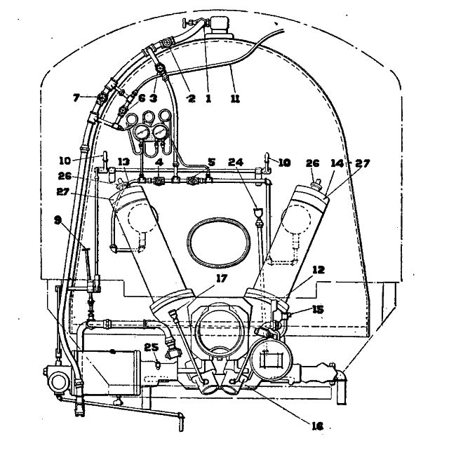
10. Q. Can the fireman direct the even distribution of coal in the fire-box?
A. Yes; by changing position of the dividing rib located in the transfer hopper, and by moving the regulating lever to either side.
11. Q. Should the sliding plates at the bottom of the tank be closed before coal is put on tank?
A. Yes, so that screw conveyor will not become clogged and inoperative. Only one slide should be opened at a time and coal fed from tank as required.
12. Q. In case the stoker becomes clogged or it is desired to reverse it for any reason, what must be done?
A. The operating rod located on the back-head of the locomotive boiler—if the piston is making a power stroke—should be moved to its lower position, and if the piston is making a return stroke, it should be moved to its upper position. This moves a small valve in the auxiliary head, bolted to reverse head, and steam is admitted to opposite head of cylinder, causing the piston to change its direction. The return of the operating rod handle to a central position causes the driving engine to resume its normal operation.
13. Q. How can the fireman observe the condition of fire in fire-box?
A. The elbows are provided with peep valves with swinging covers through which the coal supply and condition of fire may be seen.
14. Q. Why are two gauges necessary?
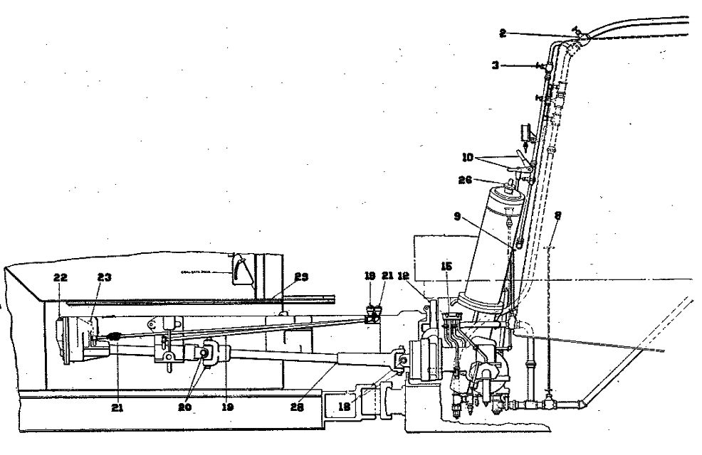
>A. The driving engine gauge on the left indicates the pressure of steam used by the driving engine. The one on the right has two indicators, the red indicator showing the steam pressure on the jet in left elbow, and the black indicator showing the pressure on the jet in the right elbow.
15. Q. When train is standing on siding for a short period, what should be done?
A. Shut stoker off by throwing operating rod on back head of locomotive boiler out of running position.
16. Q. When train is to stand for a long time or engine is left at terminal, what should be done?
A. The driving engine should be cut out entirely by closing main steam line inlet and main lubricator connection, and in winter time all drain cocks should be opened.
17. Q. If sufficient coal can not be supplied over front grates, what may be the cause?
A. Distributors may be warped and point too low, or steam jets may be plugged with pipe scale and not blowing freely.
18. Q. How would you start and operate stoker?
A. First open main valve No. 1 at steam turret. Valve 2 is then opened; this is the main valve in stoker steam line. Next open valve 3, which allows the steam to flow to the distributor jet line; open valves 4 and 5, which govern the pressure on the jets until ten pound pressure shows on the right-hand gauge. See valve 8 to the exhaust line is open, and valve 9 to the transfer hopper is closed.
19. Q. How would you start the stoker engine?
A. Place operating lever 10 in horizontal or running position. Place conveyor reversing lever 12 in forward position. Open valve 6, which allows the steam to pass to the operating valve and starts stoker running. Valve 7 is to be used as an emergency valve only in case of clogging. Stoker should be run slowly at first. Do not feed too much coal and carry a light fire.
20. Q. How would you reverse conveyor screw in tank?
A. Lower handle 10 on operation rod on boiler head to bottom position. Move screw conveyor, reverse lever 12 back to rear or reverse position, raise handle 10 on operating rod to center position.
21. Q. How would you stop conveyor screw in tank?
A. Place conveyor reversing lever 12 in center position.
22. Q. How would you reverse right or left elevator screw?
A. Raise elevator pawl shifter 26 on top of the vertical shaft to upper position.
23. Q. How would you stop right or left elevator screw?
A. Raise elevator pawl shifter 26 on top of the elevator to middle position.
24. Q. How would you locate clogs in case the stoker stalls?
A. First, shut off pressure to stoker engine cylinder by closing valve 6. Second, move operating valve lever 10 to its lowest position. Third, place tender conveyor reverse lever 12 in center. Fourth, place right elevator pawl shifter 26 in neutral position. Fifth, raise operating valve lever 10 to center position. Sixth, open valve 6 sufficiently to run left elevator to ascertain if it operates freely. Cut in right elevator by lowering pawl shifter 26, and if stoker stops, the obstruction is in the right elevator. If it continues to operate, then the obstruction is in the tank conveyor.
25. Q. How would you remove clogs?
A. Clogs in upright elevators usually occur at the bottom. Raise the door in the engine deck and remove the obstruction if in the elevator, reverse the elevator screw forcing the obstruction back down in transfer hopper. It may be a small mine spike lodged above this point, and by removing the nut at top of elevator casing and removing the door the obstruction can be easily removed.
26. Q. If the clog is in the tank conveyor, how would it be removed?
A. The clog will usually be found in the crushing zone. Reverse the tank conveyor screw, forcing the obstruction back, when it can be removed from the trough.
27. Q. How far should the conveyor screw be run backwards?
A. Not more than three revolutions.
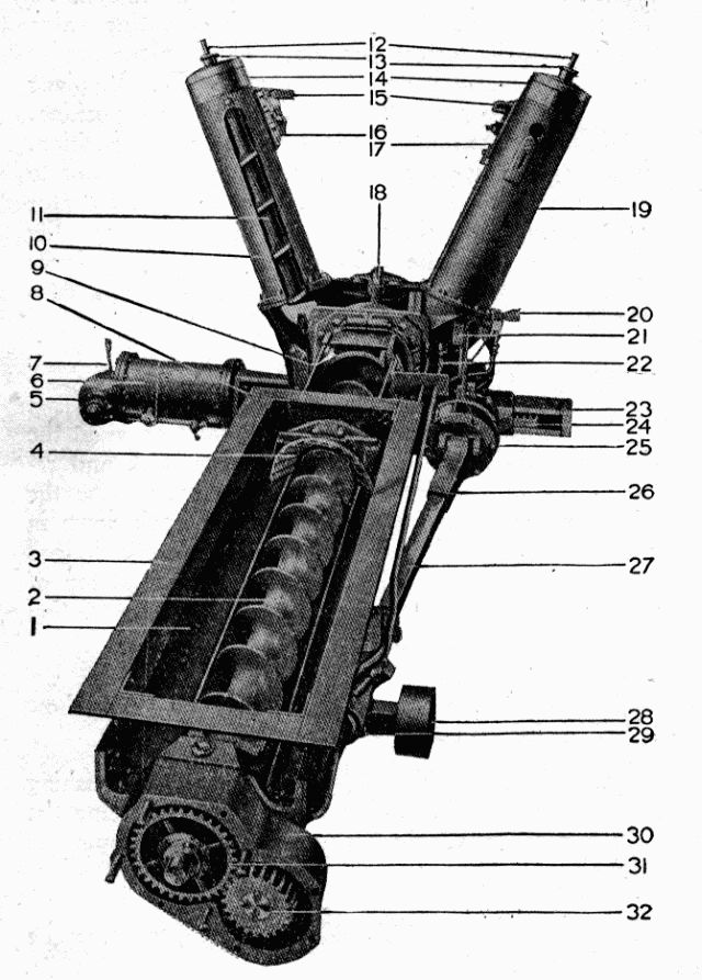
PARTS OF DUPLEX LOCOMOTIVE STOKER
1. Conveyor Trough. 2. Conveyor Screw. 3. Angle Ring. 4. Crusher. 5. Operating Head. 6. Driving Engine Cylinder. 7. Reverse Valve. 8. Piston Rod. 9. Transfer Hopper. 10. Left Elevator Casing. 11. Left Elevator Screw. 12. End of Elevator Screw Shaft. 13. Elevator Pawl Shifter. 14. Elevator Pawl Casing. 15. Distributors. 16. Left Distributor Elbow. 17. Right Distributor Elbow. 18. Dividing Rib. 19. Right Elevator Casing. 20. Oil Box. 21. Conveyor Reverse Lever. 22. Conveyor Oil Cups. 23. Rack Housing. 24. Rack. 25. Conveyor Pawl Casing. 26. Conveyor Screw Flexible Connection Sleeve. 27. Conveyor Screw Flexible Connection. 28. Conveyor Slide Support Roller. 29. Conveyor Slide Support. 30. Conveyor End Bearing and Gear Case. 31. Conveyor Screw Gear. 32. Conveyor Screw Driving Gear.
AIR BRAKE QUESTIONS
COMPRESSOR GOVERNOR
1. Q. When steam is first turned on, what must it pass through before entering the compressor?
A. The compressor governor.
2. Q. What does Fig. 1 represent?
A. This shows a sectional view of the SF compressor governor in open position.
3. Q. What is the duty of the compressor governor?
A. To automatically regulate the main reservoir pressure by controlling the steam to the compressor.
4. Q. How are the regulating portions of the governor designated?
A. The one having two pipe connections and a light regulating spring is known as the excess pressure head; the other, with a single pipe connection and heavy regulating spring, as the maximum pressure head.
5. Q. When does the excess pressure head control the flow of steam to the compressor?
A. When the automatic brake valve is in any one of its first three positions; namely, release, running and holding positions.
6. Q. With the automatic brake valve in release, running or holding position, what pressure is in chamber "f" above the diaphragm? In chamber "d" below the diaphragm?
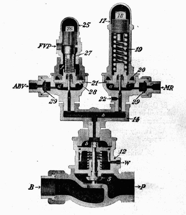
Fig. 1: The SF-4 Compressor Governor. Connections: FVP, Feed Valve Pipe. ABV, Automatic Brake Valve. MR, Main Reservoir. B, From Boiler. P, To Air Pump.
A. Air, at feed valve pipe pressure, enters at the connection marked "FVP" and flows to chamber "f" above the diaphragm; this pressure acts in conjunction with the regulating spring 27 in creating the total pressure on the diaphragm. Air at main reservoir pressure flows through the automatic brake valve to the connection marked "ABV" to chamber "d" under the diaphragm.
7. Q. At what pressure is the regulating spring in the excess pressure head adjusted?
A. Usually twenty pounds.
8. Q. With the spring adjusted at twenty pounds, what will be the total pressure on the upper side of the diaphragm?
A. Twenty pounds, plus the pressure in the feed valve pipe.
9. Q. With the feed valve adjusted at seventy pounds, and the regulating spring at twenty pounds, what pressure will be had in the main reservoir when the governor stops the compressor?
A. Ninety pounds.
10. Q. Explain the operation of the governor in controlling the compressor when a main reservoir pressure of ninety pounds is reached.
A. When the main reservoir pressure in chamber "d" slightly exceeds the pressure on top of the diaphragm it will move upward, carrying the pin valve with it. The air in chamber "d" passes by the unseated pin valve through port "b" into chamber "b" above the governor piston, forcing it downward, seating the steam valve 5, thus shutting off the steam to the compressor.
11. Q. How long will the governor remain in this position?
A. Until the main reservoir pressure falls below ninety pounds, when the combined spring and air pressure in chamber "f" will force the diaphragm 28 down, seating the pin valve. This shuts off the supply of air from chamber "d", and the air confined in chamber "b" will escape to the atmosphere through the vent port "c". The pressure now being removed from above the governor piston, the spring 9 aided by the steam pressure under the valve 5, will force the piston upward, unseating the steam valve 5, allowing steam to pass through the governor to the compressor.
12. Q. When the steam valve is seated, is steam entirely shut off from the compressor?
A. No; there is a small port drilled through the valve; its purpose is to maintain a circulation in the steam pipe and keep the compressor working slowly; thereby preventing condensation when the steam valve is closed.
13. Q. With the automatic brake valve in release, running, or holding position, does the maximum pressure head operate?
A. No; as during this time the main reservoir pressure is not sufficiently high to actuate its diaphragm.
14. Q. Where does the air come from that operates the maximum pressure head?
A. From the main reservoir direct. (See Fig. 1.)
15. Q. When does the maximum pressure head control the compressor?
A. When the automatic brake valve is in either lap, service or emergency position, also when the main reservoir cut-out cock is closed.
16. Q. How is the pressure created on top of the diaphragm in the maximum pressure head?
A. By the regulating spring 19.
17. Q. What is the adjustment of this spring?
A. Spring 19 is adjusted to the maximum pressure desired in the main reservoir usually 130 pounds.
18. Q. Explain the operation of the governor when the main reservoir pressure exceeds the tension of the regulating spring 19.
A. When the pressure in chamber "a" exceeds the tension of the regulating spring 19, the diaphragm 20 is forced upward, unseating the pin valve, allowing air to flow from chamber "a" to chamber "b" above the governor piston, forcing it down, shutting off steam and stopping the compressor.
19. Q. How long will the governor remain in this position?
A. Until the main reservoir pressure in chamber "a" under the diaphragm becomes slightly less than the adjustment of the regulating spring 19, when the diaphragm 20 will move down, seating the pin valve, shutting off the flow of air from chamber "a" to chamber "b". The air entrapped above the governor piston will escape to the atmosphere through the relief port "c"; this will allow the governor piston to raise, unseating the steam valve 5, again allowing steam to pass through the governor to the compressor.
20. Q. Is the maximum pressure head cut out in any position of the automatic brake valve?
A. No; as the air that operates this head comes direct from the main reservoir, therefore is not controlled by the brake valve.
21. Q. Is the excess pressure head cut out in any position of the brake valve?
A. Yes; as the air that operates this head comes through the automatic brake valve, and when the handle is moved beyond holding position, the port in the rotary valve seat, through which the air flows to chamber "d" is closed, thereby cutting out this head, leaving the compressor under the control of the maximum pressure head.
22. Q. What is the object of the duplex or double head governor?
A. By use of the duplex governor the main reservoir pressure may be controlled at two different predetermined pressures; as when running along the excess or low pressure head controls the compressor, at the low pressure—usually ninety pounds—this being sufficient to keep the brakes released and fully charged; whereas, in lap position, as following a brake application, the maximum or high pressure head controls the compressor at the maximum pressure used—generally 130 pounds—this for a prompt release and quick recharge of the brakes. From this it will be seen that the compressor has to work against the high pressure only during the time the brake is applied.
23. Q. In what position should the automatic brake valve handle be placed when adjusting the excess pressure head? The maximum pressure head?
A. Running position for the excess pressure head; lap position for the maximum pressure head.
24. Q. If, with the automatic brake valve handle in running position, the brake pipe and main reservoir do not stand twenty pounds apart, where would you look for the trouble?
A. Would first learn if the maximum pressure head was properly adjusted, and if it were, would then look for the trouble in the adjustment of the regulating spring in the excess pressure head.
25. Q. What should be done?
A. The regulating spring should be properly adjusted.
26. Q. How should the adjustment of the regulating spring in either pressure head be made?
A. By removing the cap nut 25 or 17 and screwing the regulating nut 26 or 18 up or down as may be required.
DEFECTS OF THE GOVERNOR
27. Q. What would be the effect if one or both of the pin valves leaked?
A. Would cause a delay in opening of the steam valve after the pin valve had seated; and if air leaks by faster than it can escape through the relief port "c", pressure will accumulate in chamber "b" and force the governor piston downward, so as to partially or wholly close the steam valve 5.
28. Q. How can you tell if the pin valves leak?
A. Leakage past the pin valve in the maximum pressure head will cause a constant blow at the relief port in all positions of the brake valve; leakage past the pin valve in the excess pressure head will cause a blow in the first three positions of the brake valve only.
29. Q. What would be the effect if the relief port "c" stopped up?
A. The compressor will not start promptly after the pin valve seats.
30. Q. What would be the effect if the drain port "W" were stopped up?
A. Steam leaking into the chamber under the governor piston will form a pressure and prevent the piston being forced downward to close the steam valve; the compressor will therefore continue to work until the main reservoir pressure is about equal to boiler pressure.
31. Q. If the pipe leading from the feed valve pipe to the excess pressure head of the governor breaks, what effect will it have on the compressor?
A. The compressor will stop when the main reservoir pressure reaches about forty-five pounds.
32. Q. If the pipe breaks, what should be done?
A. Plug the end toward the feed valve and put a blind gasket in the pipe leading from the automatic brake valve to the governor, at the connection marked ABV.
33. Q. If the pipe leading from the automatic brake valve to the governor breaks, what should be done?
A. Plug the pipe toward the brake valve; the compressor will now be controlled by the maximum pressure head.
34. Q. If the pipe leading from the main reservoir to the maximum head of the governor breaks, what should be done?
A. Plug the main reservoir end of the pipe. The excess pressure head will now control the compressor in the first three positions of the automatic brake valve handle, but will have no control after the handle is moved as far as lap position.
PARASITE GOVERNOR
35. Q. What is the purpose of the parasite governor, and where is this governor located?
A. This governor is located in the pipe connection between the main reservoir and parasite reservoir, and its purpose is to control the flow of air from the main to the parasite reservoir.
36. Q. What is the purpose of the parasite reservoir?
A. It is here that air is stored for use in all air operated devices on the locomotive, except the brake.
37. Q. Explain the operation of the parasite governor.
A. The operation of this governor is much the same as the compressor governor, and differs only in that the supply valve is open when it is in its lower position.
38. Q. At what pressure is the regulating spring adjusted?
A. About fifteen pounds.
39. Q. What pressure is required in the main reservoir before air is admitted to the parasite reservoir?
A. At least fifteen pounds above that in the brake pipe.
40. Q. What pressure is obtained in the parasite reservoir?
A. The same as that in the main reservoir, when the main reservoir pressure is fifteen pounds greater than that in the brake pipe.
41. Q. What will prevent the charging of the parasite reservoir, and what should be done?
A. This may be caused by the feed valve being improperly adjusted, sticking in open position or leakage of main reservoir air past the valve to the feed valve pipe and governor top.
WESTINGHOUSE 9½ OR 11-INCH COMPRESSOR
42. Q. What is the duty of the air compressor?
A. To furnish the compressed air used in the operation of the brakes, and all other air operated appliances on both locomotive and cars.
43. Q. Explain the operation of the steam end of the compressor.
A. When steam is turned on at the boiler it flows through the steam pipe and governor, entering the compressor at the steam enlet, then through the steam passage "a" to the reversing valve chamber "C" also to the main valve chamber "A" between the differential pistons 77 and 79. The area of the piston at the right being greater than the one at the left, the main valve is moved to the right, (See Fig. 2) admitting steam to port "b" which leads to the lower end of the steam cylinder; steam is now free to flow under the main piston, forcing it upward. When the piston has almost completed its upward stroke, the reversing plate 69 on top of the piston 65 engages a shoulder on the reversing rod 71, moving the rod and reversing valve 72 upward (See Fig. 3). The upward movement of the reversing valve closes the ports "f" and "h" and opens port "g"; thus permitting steam to enter the chamber at the right of the large piston 77, balancing the pressure on this piston, and the pressure acting on the right side of the small piston 79—the chamber at the left being open to the exhaust—will force the main valve to the left.
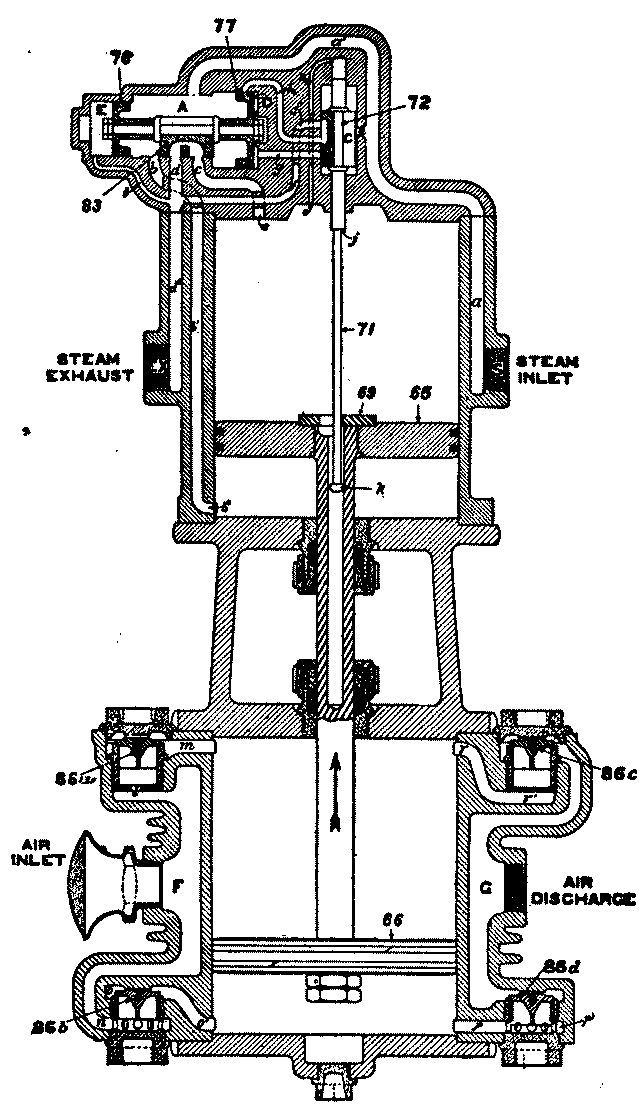
Fig. 2: Diagrammatic View, Up Stroke.
When the main valve moves to the left, steam is admitted through port "c" to the upper end of the cylinder on top of the piston 65, forcing it downward. At the same time the lower end of the cylinder is connected through exhaust cavity "b" of the main valve to the exhaust port "d", allowing the steam below the piston to escape to the atmosphere.
44. Q. When the piston has about completed its downward stroke, what takes place?
A. The reversing plate 69 engages the button "k" on the end of the reversing rod 71 pulling the rod and the reversing valve down. This movement of the reversing valve closes port "g" and the cavity in the face of the valve connects ports "f" and "h", which allows the steam in chamber "D" at the right of the large differential piston to escape to the exhaust, thus allowing the main valve to move to the right, exhausting the steam from the top end of the cylinder, and at the same time admitting steam to the lower end, causing an upward stroke of the piston.
45. Q. Explain the operation of the air end of the compressor.
A. The movement of the steam piston 65 is imparted to the air piston 66 by means of the piston rod. When the air piston moves up, a partial vacuum is formed below it, and air from the atmosphere will enter through passage "F" thence through passage "n" to the under side of receiving valve 86b (see Fig. 2), lifting this valve from its seat, and will fill the cylinder with air at about atmosphere pressure.
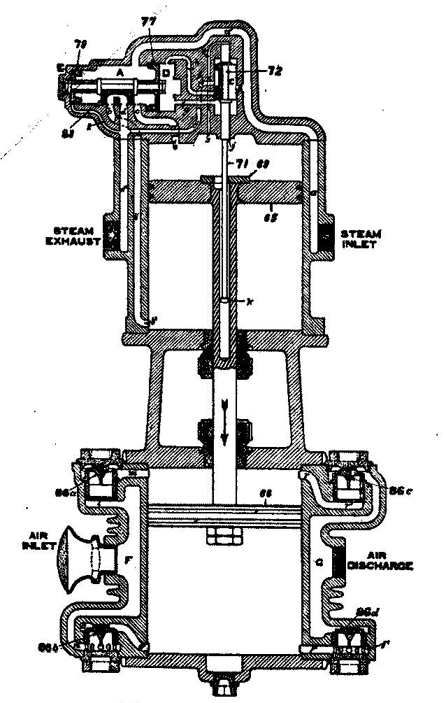
Fig. 3: Diagrammatic View, Down Stroke.
In the meantime the air above the piston, being compressed, will hold the upper receiving valve 86a to its seat, and when the pressure is slightly greater than that in the main reservoir, this pressure acting under the upper discharge valve 86c, will lift this valve from its seat and now the air will be free to flow through passage "G" to the main reservoir connection. On the down stroke the action is similar, air is taken in through the upper receiving valve 86a, while the air below the piston is being compressed and forced past the lower discharge valve 86d, to the main reservoir. (See Fig. 3.)
46. Q. What lift should the air valves have?
A. All valves should have a lift of three thirty-second of an inch.
47. Q. At what speed should the compressor be run to obtain the best results?
A. At 100 to 120 single strokes per minute.
48. Q. What kind of oil should be used in the air end of the compressor and on the swab?
A. Valve oil.
49. Q. How often should the air end of the compressor be oiled?
A. No fixed rule can be given as so much depends on the condition of the compressor, as well as the amount of work required; but in any case it should be used sparingly.
CROSS-COMPOUND COMPRESSOR
50. Q. What do Figures 4 and 5 represent?
A. These are diagramatic views of a cross-compound compressor.
51. Q. Why is this called a cross-compound compressor?
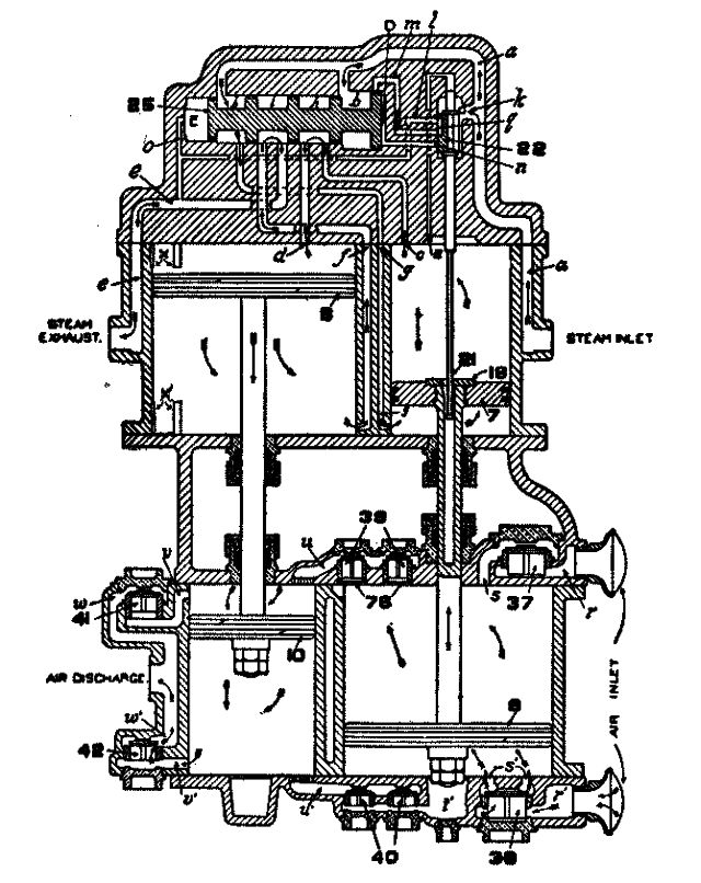
Fig. 4: Diagram of 8½" Cross-Compound Compressor. High Pressure Steam (Low Pressure Air) Piston on Its Upward Stroke
A. Because both steam and air are compounded, that is, the steam is used the second time before it is exhausted to the atmosphere, while the air is compressed the second time before it is delivered to the main reservoir.
52. Q. How many cylinders have the cross-compound compressor?
A. Four; two steam cylinders and two air cylinders.
53. Q. What is the diameter of the different cylinders?
A. The high pressure steam cylinder is 8½ inches; the low pressure steam cylinder 14½ inches; the low pressure air cylinder 14½ inches; high pressure air cylinder 9 inches.
54. Q. Explain the valve gear of this compressor.
A. The valve gear is the same as that of the 9½ or 11 inch compressor, only that a piston valve is used to distribute the steam instead of a slide valve.
55. Q. Where does the steam come from that is used in the high pressure steam cylinder?
A. Direct from the boiler.
56. Q. Where does the steam come from that is used in the low pressure steam cylinder?
A. The steam after doing work in the high pressure steam cylinder is exhausted into the low pressure steam cylinder, where it becomes the working pressure of this cylinder.
57. Q. Explain the operation of this compressor.
A. When steam is first turned on, it enters the compressor at the steam inlet (see Fig. 4) and flows through passage "a" into the reversing valve chamber "C" and on to chambers "b" and "y" against the inner faces of the differential pistons, causing the main valve to move to the right. In this position of the main valve, port "g" is open to chamber "b", thus admitting live steam to the lower end of the high pressure steam cylinder, causing an upward movement of the piston 7. When the piston 7 has nearly completed its up stroke, the reversing plate 18, which is attached to the top of this piston, comes in contact with a shoulder on the reversing rod 21, forcing it upward, carrying with it the reversing valve 22, the movement of which closes port "m", at the same time opens port "n", filling chamber "D" with live steam from chamber "C" and passage "a". This balances the pressure on the two sides of the large piston of the differential pistons, and the pressure acting against the inner side of the small piston causes the main valve to move to the left (see Fig. 5). The main valve moving to the left closes port "g" to the live steam and at the same time connects this port with port "f" leading to the lower end of the low pressure steam cylinder, causing an up stroke of the low pressure steam piston 8. In the meantime port "c", which leads to the upper end of the high pressure steam cylinder, is open to chamber "y", allowing live steam to flow down on top of the high pressure steam piston 7, forcing it downward. As the high pressure steam piston about completes its downward stroke, the reversing plate 18 engages the button on the lower end of the reversing rod 21, pulling the rod and reversing valve 22 down, closing port "n" and at the same time connecting port "m" and "l" through the exhaust cavity "q", thus allowing the steam in chamber "D" to escape to the exhaust. The pressure being removed from the outer face of the large differential piston, the main valve will again move to the right, opening port "g", admitting live steam beneath the piston 7, and at the same time connecting the upper end of the high pressure steam cylinder through port "c", chamber "h" and port "d" to the upper end of the low pressure steam cylinder, causing a downward movement of the low pressure steam piston; the steam below this piston will now be free to escape to the exhaust through port "f", chamber "i" and port "e". Thus it will be seen that the steam used in the high pressure steam cylinder is live steam from the boiler, while the steam used in the low pressure steam cylinder is the exhaust steam from the high pressure steam cylinder.
58. Q. Explain the operation of the air end of the compressor.
A. As the low pressure air piston 9 moves up, a partial vacuum is created beneath it and air from the atmosphere enters the air inlet and passage "r" past the lower receiving valve 38 and fills the lower end of the cylinder with air at about atmospheric pressure (see Fig. 4). In the meantime the air above the piston being compressed will hold the upper receiving valve 37 to its seat, thus preventing a back-flow of air to the atmosphere; at the same time the upper intermediate discharge valves 39 are forced from their seats, allowing the air from the low pressure air cylinder to flow through passage "u" to the high pressure air cylinder, the piston of which is now moving downward. The air beneath the high pressure air piston 10 being compressed will hold the lower intermediate discharge valves 40 to their seats, thus preventing the air in the high pressure air cylinder flowing back to the low pressure air cylinder. When the pressure in the high pressure air cylinder becomes slightly greater than the main reservoir pressure, the final discharge valve 42 will be forced from its seat and the air beneath the piston allowed to flow to the main reservoir through passage "w". On the opposite strokes of these pistons air is compressed in a similar manner, but the opposite air valves are used.
Fig. 5: Diagram of 8½" Cross-Compound Compressor. The High Pressure Steam (Low Pressure Air) Piston on Its Downward Stroke
59. Q. How many valves are there in the air end of the compressor?
A. Ten; two upper and two lower receiving valves; two upper and two lower intermediate discharge valves; one upper and one lower final discharge valves.
60. Q. Are the air valves all the same size?
A. No; the receiving and final discharge valves are the same size and of the size used in the 11-inch compressor, while the intermediate valves are the same as used in the 9½-inch compressor. The receiving and final discharge valves are two inches in diameter, while the intermediate valves are one and one-half inches.
61. Q. What lift is given the different air valves?
A. All valves have 3/32-inch lift.
DEFECTS OF THE COMPRESSOR
62. Q. What are some of the common causes for the compressor stopping?
A. Lack of lubrication; bent, worn or broken reversing rod; loose or worn reversing plate; nuts on air end of piston rod coming off; defective compressor governor; and, in addition with the cross-compound compressor, final discharge valve broken or stuck open, or packing rings in main valve pistons breaking and catching in the steam ports.
63. Q. What will cause the piston to make an uneven stroke?
A. This may be caused by a broken or stuck open air valve, or air valves not having proper lift. Where the piston short strokes, it is generally caused by over-lubrication of the steam end.
64. Q. What are some of the common causes for the compressor running hot?
A. The overheating of the compressor may be due to any one of the following causes: Running at high speed; working against high pressure; packing rings in air piston badly worn; air cylinder worn; defective air valves; air passages or air discharge pipe partially stopped up; leaky piston rod packing; lack of lubrication.
65. Q. What will cause the compressor to run slow?
A. This may be caused by leaky air piston packing rings; final discharge valves leaking, or air passages partially stopped up. A defective governor may also cause the compressor to run slow.
66. Q. What will cause the compressor to run very fast and heat, and not compress any air?
A. This may be caused by the strainer becoming clogged with ice or dirt, preventing air entering the cylinder.
67. Q. If, when steam is first turned on, the piston makes a stroke up and stops, where would you look for the trouble?
A. The shoulder on the reversing rod may be worn; the opening in the reversing plate too large to engage the shoulder on the reversing rod; loose reversing plate studs preventing the piston traveling far enough to reverse the compressor, or the main valve stuck in its position at the right.
68. Q. If the piston makes a stroke up and a stroke down and stops, where is the trouble?
A. This may be caused by a loose reversing plate, or the button on the lower end of the reversing rod worn or broken off, or the nuts off the piston rod in the air end, or the main valve stuck in its position at the left.
69. Q. What will cause the piston to make a quick up stroke?
A. This may be caused by a broken or stuck open upper receiving or lower discharge valve.
70. Q. What will cause the piston to make a quick down stroke?
A. Lower receiving or upper discharge valve broken or stuck open.
71. Q. If a receiving valve breaks or sticks open, how may it be located?
A. The air will flow back to the atmosphere as the piston moves toward the defective valve and may be detected by holding the hand over the strainer.
72. Q. If a receiving valve in a cross-compound compressor breaks, what may be done?
A. Remove the broken valve, blocking the opening made by its removal, and as there are two upper and two lower receiving valves the compressor will now take air through the other valve.
73. Q. If an intermediate discharge valve breaks or sticks open, how may it be located?
A. No air will be taken in to that end of the compressor as the piston moves from the defective valve, and may be located by holding the hand over the strainer.
74. Q. If an intermediate discharge valve breaks, what may be done?
A. Remove the broken valve, blocking the opening made by its removal, and as there are two upper and two lower intermediate discharge valves the air will now pass from the low pressure cylinder to the high pressure cylinder through the other valve.
75. Q. If a final discharge valve breaks, what effect will it have on the compressor?
A. Will cause the compressor to stop when the main reservoir pressure is in excess of forty pounds.
76. Q. How would you test for a defective final discharge valve?
A. To test for this defect, bleed the main reservoir pressure below forty pounds, and if the compressor starts it indicates a defective discharge valve.
77. Q. If a final discharge valve breaks, what may be done?
A. As the receiving valves and final discharge valves are the same size, the defective valve may be replaced by one of the receiving valves, blocking the opening made by the removal of the receiving valve.
78. Q. Where piston rod packing is blowing bad, what may be done to stop it?
A. This generally indicates lack of lubrication, and by cleaning and oiling the swab the trouble may be overcome. However, there are times when leakage by the packing is so great that the oil is blown off the swab as fast as it is applied, therefore is of no value in lubricating the parts. Where this condition exists, a little hard grease wrapped up in an old flag and tied around the piston rod will ensure its being lubricated.
79. Q. If the compressor stops, how can you tell if the governor is responsible for the trouble?
A. By opening the drain cock in the steam passage between the governor and the compressor; if steam flows freely, the trouble is in the compressor; if not, it is in the governor.
80. Q. How may a compressor often be started when it stops?
A. By closing the steam throttle for a few seconds, then opening it quickly; if this does not start it, try tapping the main valve chamber. This will usually overcome the trouble where the compressor stops on account of lack of lubrication.
81. Q. What will cause a compressor to short-stroke or dance?
A. Too much oil in the steam end; bent reversing rod; or low steam pressure, as when the governor has almost shut off the steam.
ENGINEER'S BRAKE VALVE
82. Q. Name the different positions of the G-6 and H-6 brake valves.
A. Release, running, lap, service, and emergency position, with the G-6; release, running, holding, lap, service, and emergency positions, with the H-6.
83. Q. What is the purpose of release position?
A. To provide a large and direct opening from the main reservoir to the brake pipe, for the free flow of air, when charging and recharging the brakes.
84. Q. What pressure will be had in the brake pipe if the brake valve be left in release position?
A. Main reservoir pressure.
85. Q. Can the locomotive brake be released by the automatic brake valve in release position, when using the H-6 valve?
A. No; as the port in the automatic brake valve to which the distributing valve release pipe is attached is blanked in this position of the valve.
86. Q. What is the purpose of running position, and when should it be used?
A. This is the proper position for the brake valve when the brakes are charged and not in use, also when it is desired to release the locomotive brake with this valve. In this position the brake pipe pressure is maintained at a predetermined amount by the feed valve, as all air that now enters the brake pipe must pass through the feed valve.
87. Q. What is the purpose of holding position?
A. To hold the locomotive brake applied while recharging the brakes. The charging of the brake pipe and equalizing reservoir is the same in holding as in running position.
88. Q. What is the purpose of lap position?
A. To hold both the locomotive and train brakes applied after an automatic application.
89. Q. What is the purpose of service position?
A. This position of the brake valve enables the engineer to make a gradual reduction of brake pipe pressure, thus causing a service application of the brakes.
90. Q. What is the purpose of emergency position?
A. In this position of the brake valve, the brake pipe is connected directly with the atmosphere through the large ports in the valve, causing a sudden reduction of brake pipe pressure, this in turn causing the distributing valve on the engine and all operating triple valves on cars in the train to move to emergency position, thus insuring a quick and full application of the brake.
91. Q. How should the brake valve be handled when making an emergency application of the brake?
A. The valve should be placed in full emergency position and left there until the train stops, even though the danger may have disappeared.
DEFECTS OF THE BRAKE VALVE
92. Q. What will cause a constant blow at the brake pipe exhaust port, and what may be done to overcome it?
A. This indicates that the brake pipe exhaust valve is being held off its seat, due no doubt to dirt; tapping the side of the valve will sometimes stop the blow; if not, close the brake pipe cut-out cock and make a heavy service reduction; next, place the brake valve handle in release position. This will cause a strong blow at the exhaust port, which will invariably remove the trouble.
93. Q. If the pipe connecting the brake valve with the equalizing reservoir breaks, can both locomotive and train brakes be operated with the automatic brake valve?
A. Yes; by placing a blind gasket in the pipe connection at the brake valve and plugging the brake pipe exhaust port. To apply the brake, move the handle carefully toward emergency position, making a gradual reduction of brake pipe pressure through the direct exhaust ports of the brake valve; when the desired reduction is made, the handle should be moved gradually back to lap position.
94. Q. What would be the effect if the handle were moved to lap quickly?
A. Would cause the release of the brakes on the head end of the train.
95. Q. What will cause air to blow at the brake pipe exhaust port when the handle is moved to lap position?
A. This is caused by a leak from the equalizing reservoir or its connections, which reduces the pressure in chamber "D" above the equalizing piston, allowing brake pipe pressure under the piston to force it up, unseating the brake pipe exhaust valve, permitting brake pipe air to flow to the atmosphere.
96. Q. What is the purpose of the equalizing reservoir?
A. The purpose of the equalizing reservoir is to furnish a larger volume of air above the equalizing piston than is found in chamber "D", thus to enable the engineer to make a graduated reduction of the pressure above the equalizing piston.
97. Q. What defect will cause the brake pipe and main reservoir pressure to equalize when the handle is in running position?
A. This may be caused by leakage past the rotary valve, defective body gasket, or leakage by the feed valve or its case gasket. To determine which part is at fault, close the cut-out cock under the brake valve and move the handle to service position, exhausting all air from chamber "D" and the brake pipe; return the handle to lap position. Leakage of air past the rotary valve is generally into the brake pipe port which allows the air to come in under the equalizing piston, thus forcing it upward, unseating the brake pipe exhaust valve, allowing this air to escape to the atmosphere at the brake pipe exhaust port. Leakage past the body gasket allows air to enter chamber "D", above the equalizing piston, holding it in its lower position, keeping the brake pipe exhaust port closed, thereby preventing the escape of this air to the atmosphere. Since the capacity of the equalizing reservoir and chamber "D" is small, such a leak will cause the black hand to quickly move up to the position of the red hand. To determine if the leakage be in the feed valve or its gasket, recharge the brake pipe to some pressure below the adjustment of the feed valve, then place the handle in lap position. If the black hand on the air gauge remains stationary, it is fair to assume that the trouble is in the feed valve or its gasket, as in this position of the brake valve the feed valve is cut out.
98. Q. With the engine alone, the brake pipe pressure will equalize with that in the main reservoir, while when coupled to a train the pressure will remain at that for which the feed valve is adjusted; where is the trouble?
A. This is caused by light leakage of main reservoir air into the brake pipe, and may come past the rotary valve, body gasket, or feed valve, and with the lone engine is sufficient to raise the brake pipe pressure to that in the main reservoir; while, when coupled to a train, the brake pipe leakage of which is greater than this amount, this leakage will not be noticed.