THEORY AND PRACTICE OF PERSPECTIVE
Reading edition
BY
G. A. STOREY, A.R.A.
TEACHER OF PERSPECTIVE AT THE ROYAL ACADEMY
‘QUÎ FIT?’
OXFORD AT THE CLARENDON PRESS
1910
OXFORD
PRINTED AT THE CLARENDON PRESS BY HORACE HART, M.A. PRINTER TO THE UNIVERSITY
DEDICATED
TO
SIR EDWARD J. POYNTER
BARONET
PRESIDENT OF THE ROYAL ACADEMY
IN TOKEN OF FRIENDSHIP
AND REGARD
PREFACE
It is much easier to understand and remember a thing when a reason is given for it, than when we are merely shown how to do it without being told why it is so done; for in the latter case, instead of being assisted by reason, our real help in all study, we have to rely upon memory or our power of imitation, and to do simply as we are told without thinking about it. The consequence is that at the very first difficulty we are left to flounder about in the dark, or to remain inactive till the master comes to our assistance.
Now in this book it is proposed to enlist the reasoning faculty from the very first: to let one problem grow out of another and to be dependent on the foregoing, as in geometry, and so to explain each thing we do that there shall be no doubt in the mind as to the correctness of the proceeding. The student will thus gain the power of finding out any new problem for himself, and will therefore acquire a true knowledge of perspective.
CONTENTS
BOOK I
page
The Necessity of the Study of Perspective To Painters, Sculptors, and Architects 1
What Is Perspective? 6
The Theory of Perspective:
I. Definitions 13
II. The Point of Sight, the Horizon, and the Point of Distance. 15
III. Point of Distance 16
IV. Perspective of a Point, Visual Rays, &c. 20
V. Trace and Projection 21
VI. Scientific Definition of Perspective 22
Rules:
VII. The Rules and Conditions of Perspective 24
VIII. A Table or Index of the Rules of Perspective 40
BOOK II
The Practice of Perspective:
IX. The Square in Parallel Perspective 42
X. The Diagonal 43
XI. The Square 43
XII. Geometrical and Perspective Figures Contrasted 46
XIII. Of Certain Terms made use of in Perspective 48
XIV. How to Measure Vanishing or Receding Lines 49
XV. How to Place Squares in Given Positions 50
XVI. How to Draw Pavements, &c. 51
XVII. Of Squares placed Vertically and at Different Heights, or the Cube in Parallel Perspective 53
XVIII. The Transposed Distance 53
XIX. The Front View of the Square and of the Proportions of Figures at Different Heights 54
XX. Of Pictures that are Painted according to the Position they are to Occupy 59
XXI. Interiors 62
XXII. The Square at an Angle of 45° 64
XXIII. The Cube at an Angle of 45° 65
XXIV. Pavements Drawn by Means of Squares at 45° 66
XXV. The Perspective Vanishing Scale 68
XXVI. The Vanishing Scale can be Drawn to any Point on the Horizon 69
XXVII. Application of Vanishing Scales to Drawing Figures 71
XXVIII. How to Determine the Heights of Figures on a Level Plane 71
XXIX. The Horizon above the Figures 72
XXX. Landscape Perspective 74
XXXI. Figures of Different Heights. The Chessboard 74
XXXII. Application of the Vanishing Scale to Drawing Figures at an Angle when their Vanishing Points are Inaccessible or Outside the Picture 77
XXXIII. The Reduced Distance. How to Proceed when the Point of Distance is Inaccessible 77
XXXIV. How to Draw a Long Passage or Cloister by Means of the Reduced Distance 78
XXXV. How to Form a Vanishing Scale that shall give the Height, Depth, and Distance of any Object in the Picture 79
XXXVI. Measuring Scale on Ground 81
XXXVII. Application of the Reduced Distance and the Vanishing Scale to Drawing a Lighthouse, &c. 84
XXXVIII. How to Measure Long Distances such as a Mile or Upwards 85
XXXIX. Further Illustration of Long Distances and Extended Views. 87
XL. How to Ascertain the Relative Heights of Figures on an Inclined Plane 88
XLI. How to Find the Distance of a Given Figure or Point from the Base Line 89
XLII. How to Measure the Height of Figures on Uneven Ground 90
XLIII. Further Illustration of the Size of Figures at Different Distances and on Uneven Ground 91
XLIV. Figures on a Descending Plane 92
XLV. Further Illustration of the Descending Plane 95
XLVI. Further Illustration of Uneven Ground 95
XLVII. The Picture Standing on the Ground 96
XLVIII. The Picture on a Height 97
BOOK III
XLIX. Angular Perspective 98
L. How to put a Given Point into Perspective 99
LI. A Perspective Point being given, Find its Position on the Geometrical Plane 100
LII. How to put a Given Line into Perspective 101
LIII. To Find the Length of a Given Perspective Line 102
LIV. To Find these Points when the Distance-Point is Inaccessible 103
LV. How to put a Given Triangle or other Rectilineal Figure into Perspective 104
LVI. How to put a Given Square into Angular Perspective 105
LVII. Of Measuring Points 106
LVIII. How to Divide any Given Straight Line into Equal or Proportionate Parts 107
LIX. How to Divide a Diagonal Vanishing Line into any Number of Equal or Proportional Parts 107
LX. Further Use of the Measuring Point O 110
LXI. Further Use of the Measuring Point O 110
LXII. Another Method of Angular Perspective, being that Adopted in our Art Schools 112
LXIII. Two Methods of Angular Perspective in one Figure 115
LXIV. To Draw a Cube, the Points being Given 115
LXV. Amplification of the Cube Applied to Drawing a Cottage 116
LXVI. How to Draw an Interior at an Angle 117
LXVII. How to Correct Distorted Perspective by Doubling the Line of Distance 118
LXVIII. How to Draw a Cube on a Given Square, using only One Vanishing Point 119
LXIX. A Courtyard or Cloister Drawn with One Vanishing Point 120
LXX. How to Draw Lines which shall Meet at a Distant Point, by Means of Diagonals 121
LXXI. How to Divide a Square Placed at an Angle into a Given Number of Small Squares 122
LXXII. Further Example of how to Divide a Given Oblique Square into a Given Number of Equal Squares, say Twenty-five 122
LXXIII. Of Parallels and Diagonals 124
LXXIV. The Square, the Oblong, and their Diagonals 125
LXXV. Showing the Use of the Square and Diagonals in Drawing Doorways, Windows, and other Architectural Features 126
LXXVI. How to Measure Depths by Diagonals 127
LXXVII. How to Measure Distances by the Square and Diagonal 128
LXXVIII. How by Means of the Square and Diagonal we can Determine the Position of Points in Space 129
LXXIX. Perspective of a Point Placed in any Position within the Square 131
LXXX. Perspective of a Square Placed at an Angle. New Method 133
LXXXI. On a Given Line Placed at an Angle to the Base Draw a Square in Angular Perspective, the Point of Sight, and Distance, being given 134
LXXXII. How to Draw Solid Figures at any Angle by the New Method 135
LXXXIII. Points in Space 137
LXXXIV. The Square and Diagonal Applied to Cubes and Solids Drawn Therein 138
LXXXV. To Draw an Oblique Square in Another Oblique Square without Using Vanishing-points 139
LXXXVI. Showing how a Pedestal can be Drawn by the New Method 141
LXXXVII. Scale on Each Side of the Picture 143
LXXXVIII. The Circle 145
LXXXIX. The Circle in Perspective a True Ellipse 145
XC. Further Illustration of the Ellipse 146
XCI. How to Draw a Circle in Perspective Without a Geometrical Plan 148
XCII. How to Draw a Circle in Angular Perspective 151
XCIII. How to Draw a Circle in Perspective more Correctly, by Using Sixteen Guiding Points 152
XCIV. How to Divide a Perspective Circle into any Number of Equal Parts 153
XCV. How to Draw Concentric Circles 154
XCVI. The Angle of the Diameter of the Circle in Angular and Parallel Perspective 156
XCVII. How to Correct Disproportion in the Width of Columns 157
XCVIII. How to Draw a Circle over a Circle or a Cylinder 158
XCIX. To Draw a Circle Below a Given Circle 159
C. Application of Previous Problem 160
CI. Doric Columns 161
CII. To Draw Semicircles Standing upon a Circle at any Angle 162
CIII. A Dome Standing on a Cylinder 163
CIV. Section of a Dome or Niche 164
CV. A Dome 167
CVI. How to Draw Columns Standing in a Circle 169
CVII. Columns and Capitals 170
CVIII. Method of Perspective Employed by Architects 170
CIX. The Octagon 172
CX. How to Draw the Octagon in Angular Perspective 173
CXI. How to Draw an Octagonal Figure in Angular Perspective 174
CXII. How to Draw Concentric Octagons, with Illustration of a Well 174
CXIII. A Pavement Composed of Octagons and Small Squares 176
CXIV. The Hexagon 177
CXV. A Pavement Composed of Hexagonal Tiles 178
CXVI. A Pavement of Hexagonal Tiles in Angular Perspective 181
CXVII. Further Illustration of the Hexagon 182
CXVIII. Another View of the Hexagon in Angular Perspective 183
CXIX. Application of the Hexagon to Drawing a Kiosk 185
CXX. The Pentagon 186
CXXI. The Pyramid 189
CXXII. The Great Pyramid 191
CXXIII. The Pyramid in Angular Perspective 193
CXXIV. To Divide the Sides of the Pyramid Horizontally 193
CXXV. Of Roofs 195
CXXVI. Of Arches, Arcades, Bridges, &c. 198
CXXVII. Outline of an Arcade with Semicircular Arches 200
CXXVIII. Semicircular Arches on a Retreating Plane 201
CXXIX. An Arcade in Angular Perspective 202
CXXX. A Vaulted Ceiling 203
CXXXI. A Cloister, from a Photograph 206
CXXXII. The Low or Elliptical Arch 207
CXXXIII. Opening or Arched Window in a Vault 208
CXXXIV. Stairs, Steps, &c. 209
CXXXV. Steps, Front View 210
CXXXVI. Square Steps 211
CXXXVII. To Divide an Inclined Plane into Equal Parts—such as a Ladder Placed against a Wall 212
CXXXVIII. Steps and the Inclined Plane 213
CXXXIX. Steps in Angular Perspective 214
CXL. A Step Ladder at an Angle 216
CXLI. Square Steps Placed over each other 217
CXLII. Steps and a Double Cross Drawn by Means of Diagonals and one Vanishing Point 218
CXLIII. A Staircase Leading to a Gallery 221
CXLIV. Winding Stairs in a Square Shaft 222
CXLV. Winding Stairs in a Cylindrical Shaft 225
CXLVI. Of the Cylindrical Picture or Diorama 227
BOOK IV
CXLVII. The Perspective of Cast Shadows 229
CXLVIII. The Two Kinds of Shadows 230
CXLIX. Shadows Cast by the Sun 232
CL. The Sun in the Same Plane as the Picture 233
CLI. The Sun Behind the Picture 234
CLII. Sun Behind the Picture, Shadows Thrown on a Wall 238
CLIII. Sun Behind the Picture Throwing Shadow on an Inclined Plane 240
CLIV. The Sun in Front of the Picture 241
CLV. The Shadow of an Inclined Plane 244
CLVI. Shadow on a Roof or Inclined Plane 245
CLVII. To Find the Shadow of a Projection or Balcony on a Wall 246
CLVIII. Shadow on a Retreating Wall, Sun in Front 247
CLIX. Shadow of an Arch, Sun in Front 249
CLX. Shadow in a Niche or Recess 250
CLXI. Shadow in an Arched Doorway 251
CLXII. Shadows Produced by Artificial Light 252
CLXIII. Some Observations on Real Light and Shade 253
CLXIV. Reflection 257
CLXV. Angles of Reflection 259
CLXVI. Reflections of Objects at Different Distances 260
CLXVII. Reflection in a Looking-glass 262
CLXVIII. The Mirror at an Angle 264
CLXIX. The Upright Mirror at an Angle of 45° to the Wall 266
CLXX. Mental Perspective 269
Index 270
BOOK FIRST
THE NECESSITY OF THE STUDY OF PERSPECTIVE TO PAINTERS, SCULPTORS, AND ARCHITECTS
Leonardo da Vinci tells us in his celebrated Treatise on Painting that the young artist should first of all learn perspective, that is to say, he should first of all learn that he has to depict on a flat surface objects which are in relief or distant one from the other; for this is the simple art of painting. Objects appear smaller at a distance than near to us, so by drawing them thus we give depth to our canvas. The outline of a ball is a mere flat circle, but with proper shading we make it appear round, and this is the perspective of light and shade.
‘The next thing to be considered is the effect of the atmosphere and light. If two figures are in the same coloured dress, and are standing one behind the other, then they should be of slightly different tone, so as to separate them. And in like manner, according to the distance of the mountains in a landscape and the greater or less density of the air, so do we depict space between them, not only making them smaller in outline, but less distinct.’1
Sir Edwin Landseer used to say that in looking at a figure in a picture he liked to feel that he could walk round it, and this exactly expresses the impression that the true art of painting should make upon the spectator.
There is another observation of Leonardo’s that it is well I should here transcribe; he says: ‘Many are desirous of learning to draw, and are very fond of it, who are notwithstanding void of a proper disposition for it. This may be known by their want of perseverance; like boys who draw everything in a hurry, never finishing or shadowing.’ This shows they do not care for their work, and all instruction is thrown away upon them. At the present time there is too much of this ‘everything in a hurry’,
Unfortunately, this study is too often neglected by our painters, some of them even complacently confessing their ignorance of it; while the ordinary student either turns from it with distaste, or only endures going through it with a view to passing an examination, little thinking of what value it will be to him in working out his pictures. Whether the manner of teaching perspective is the cause of this dislike for it, I cannot say; but certainly most of our English books on the subject are anything but attractive.
All the great masters of painting have also been masters of perspective, for they knew that without it, it would be impossible to carry out their grand compositions. In many cases they were even inspired by it in choosing their subjects. When one looks at those sunny interiors, those corridors and courtyards by De Hooghe, with their figures far off and near, one feels that their charm consists greatly in their perspective, as well as in their light and tone and colour. Or if we study those Venetian masterpieces by Paul Veronese, Titian, Tintoretto, and others, we become convinced that it was through their knowledge of perspective that they gave such space and grandeur to their canvases.
I need not name all the great artists who have shown their interest and delight in this study, both by writing about it and practising it, such as Albert Dürer and others, but I cannot leave out our own Turner, who was one of the greatest masters in this respect that ever lived; though in his case we can only judge of the results of his knowledge as shown in his pictures, for although he was Professor of Perspective at the Royal Academy in 1807—over a hundred years ago—and took great pains with the diagrams he prepared to illustrate his lectures, they seemed to the students to be full of confusion and obscurity; nor am I aware that any record of them remains, although they must have contained some valuable teaching, had their author possessed the art of conveying it.
However, we are here chiefly concerned with the necessity of this study, and of the necessity of starting our work with it.
If a ceiling has to be painted with figures floating or flying in the air, or sitting high above us, then our perspective must take a different form, and the point of sight will be above our heads instead of on the horizon; nor can these difficulties be overcome without an adequate knowledge of the science, which will enable us to work out for ourselves any new problems of this kind that we may have to solve.
Then again, with a view to giving different effects or impressions in this decorative work, we must know where to place the horizon and the points of sight, for several of the latter are sometimes required when dealing with large surfaces such as the painting of walls, or stage scenery, or panoramas depicted on a cylindrical canvas and viewed from the centre thereof, where a fresh point of sight is required at every twelve or sixteen feet.
Without a true knowledge of perspective, none of these things can be done. The artist should study them in the great compositions of the masters, by analysing their pictures and seeing
We must remember that the line of the horizon should be as nearly as possible on a level with the eye, as it is in nature; and yet one of the commonest mistakes in our exhibitions is the bad placing of this line. We see dozens of examples of it, where in full-length portraits and other large pictures intended to be seen from below, the horizon is placed high up in the canvas instead of low down; the consequence is that compositions so treated not only lose in grandeur and truth, but appear to be toppling over, or give the impression of smallness rather than bigness. Indeed, they look like small pictures enlarged, which is a very different thing from a large design. So that, in order to see them properly, we should mount a ladder to get upon a level with their horizon line (see Fig. 66, double-page illustration).
We have here spoken in a general way of the importance of this study to painters, but we shall see that it is of almost equal importance to the sculptor and the architect.
A sculptor student at the Academy, who was making his drawings rather carelessly, asked me of what use perspective was to a sculptor. ‘In the first place,’ I said, ‘to reason out apparently difficult problems, and to find how easy they become, will improve your mind; and in the second, if you have to do monumental work, it will teach you the exact size to make your figures according to the height they are to be placed, and also the boldness with which they should be treated to give them their full effect.’
I cannot help thinking that the reason our public monuments so often fail to impress us with any sense of grandeur is in a great measure owing to the neglect of the scientific study of perspective. As an illustration of what I mean, let the student look at a good engraving or photograph of the Arch of Constantine at Rome, or the Tombs of the Medici, by Michelangelo, in the sacristy of San Lorenzo at Florence. And then, for an example of a mistake in the placing of a colossal figure, let him turn to the Tomb of Julius II in San Pietro in Vinculis, Rome, and he will see that the figure of Moses, so grand in itself, not only loses much of its dignity by being placed on the ground instead of in the niche above it, but throws all the other figures out of proportion or harmony, and was quite contrary to Michelangelo’s intention. Indeed, this tomb, which was to have been the finest thing of its kind ever done, was really the tragedy of the great sculptor’s life.
The same remarks apply in a great measure to the architect as to the sculptor. The old builders knew the value of a knowledge of perspective, and, as in the case of Serlio, Vignola, and others, prefaced their treatises on architecture with chapters on geometry and perspective. For it showed them how to give proper proportions to their buildings and the details thereof; how to give height and importance both to the interior and exterior; also to give the right sizes of windows, doorways, columns, vaults, and other parts, and the various heights they should make their towers, walls, arches, roofs, and so forth. One of the most beautiful examples of the application of this knowledge to architecture is the Campanile of the Cathedral, at Florence, built by Giotto and Taddeo Gaddi, who were painters as well as architects. Here it will be seen that the height of the windows is increased as they are placed higher up in the building, and the top windows or openings into the belfry are about six times the size of those in the lower story.
WHAT IS PERSPECTIVE?
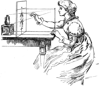
Fig. 1.
Perspective is a subtle form of geometry; it represents figures and objects not as they are but as we see them in space, whereas geometry represents figures not as we see them but as they are. When we have a front view of a figure such as a square, its perspective and geometrical appearance is the same, and we see it as it really is, that is, with all its sides equal and all its angles right angles, the perspective only varying in size according to the distance we are from it; but if we place that square flat on the table and look at it sideways or at an angle, then we become conscious of certain changes in its form—the side farthest from us appears shorter than that near to us, A (Fig. 2) is a geometrical square and B is the same square seen in perspective.


Fig. 2.
The science of perspective gives the dimensions of objects seen in space as they appear to the eye of the spectator, just as a perfect tracing of those objects on a sheet of glass placed vertically between him and them would do; indeed its very name is derived from perspicere, to see through. But as no tracing done by hand could possibly be mathematically correct, the mathematician teaches us how by certain points and measurements we may yet give a perfect image of them. These images are called projections, but the artist calls them pictures. In this sketch K is the vertical transparent plane or picture, O is a cube placed on one side of it. The young student is the spectator on the other side of it, the dotted lines drawn from the corners of the cube to the eye of the spectator are the visual rays, and the points on the transparent picture plane where these visual rays pass through it indicate the perspective position
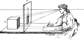
Fig. 3.
Perspective up to a certain point is a pure science, not depending upon the accidents of vision, but upon the exact laws of reasoning. Nor is it to be considered as only pertaining to the craft of the painter and draughtsman. It has an intimate connexion with our mental perceptions and with the ideas that are impressed upon the brain by the appearance of all that surrounds us. If we saw everything as depicted by plane geometry, that is, as a map, we should have no difference of view, no variety of ideas, and we should live in a world of unbearable monotony; but as we see everything in perspective, which is infinite in its variety of aspect, our minds are subjected to countless phases of thought, making the world around us constantly interesting, so it is devised that we shall see the infinite wherever we turn, and marvel at it, and delight in it, although perhaps in many cases unconsciously.
In perspective, as in geometry, we deal with parallels, squares, triangles, cubes, circles, &c.; but in perspective the same figure takes an endless variety of forms, whereas in geometry it has but one. Here are three equal geometrical squares: they are all alike. Here are three equal perspective squares, but all varied
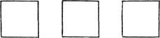
Fig. 4.
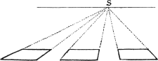
Fig. 5.
It is in proving that, notwithstanding this difference of appearance, the figures do represent the same form, that much of our work consists; and for those who care to exercise their reasoning powers it becomes not only a sure means of knowledge, but a study of the greatest interest.
Perspective is said to have been formed into a science about the fifteenth century. Among the names mentioned by the unknown but pleasant author of The Practice of Perspective, written by a Jesuit of Paris in the eighteenth century, we find Albert Dürer, who has left us some rules and principles in the fourth book of his Geometry; Jean Cousin, who has an express treatise on the art wherein are many valuable things; also Vignola, who altered the plans of St. Peter’s left by Michelangelo; Serlio, whose treatise is one of the best I have seen of these early writers; Du Cerceau, Serigati, Solomon de Cause, Marolois, Vredemont; Guidus Ubaldus, who first introduced foreshortening; the Sieur de Vaulizard, the Sieur Dufarges, Joshua Kirby, for whose Method of Perspective made Easy (?) Hogarth drew the well-known frontispiece; and lastly, the above-named Practice of Perspective by a Jesuit of Paris, which is very clear and excellent as far as it goes, and was the book used by Sir Joshua Reynolds.2 But nearly all these authors treat chiefly of parallel perspective, which they do with clearness and simplicity, and also mathematically, as shown in the short treatise in Latin by Christian Wolff, but they scarcely touch upon the more difficult problems of angular and oblique perspective. Of modern books, those to which I am most indebted are the Traité Pratique de Perspective of M. A. Cassagne (Paris, 1873), which is thoroughly artistic, and full of pictorial examples admirably done; and to M. Henriet’s Cours Rational de Dessin. There are many other foreign books of excellence, notably M. Thibault's Perspective, and some German and Swiss books, and yet, notwithstanding this imposing array of authors, I venture to say that many new features and original Fig. 162, &c.), a new method of angular perspective which dispenses with the cumbersome setting out usually adopted, and enables us to draw figures at any angle without vanishing lines, &c., and is almost, if not quite, as simple as parallel perspective (see p. 133, Fig. 150, &c.). How to measure distances by the square and diagonal, and to draw interiors thereby (p. 128, Fig. 144). How to explain the theory of perspective by ocular demonstration, using a vertical sheet of glass with strings, placed on a drawing-board, which I have found of the greatest use (see p. 29, Fig. 29). Then again, I show how all our perspective can be done inside the picture; that we can measure any distance into the picture from a foot to a mile or twenty miles (see p. 86, Fig. 94); how we can draw the Great Pyramid, which stands on thirteen acres of ground, by putting it 1,600 feet off (Fig. 224), &c., &c. And while preserving the mathematical science, so that all our operations can be proved to be correct, my chief aim has been to make it easy of application to our work and consequently useful to the artist.
The Egyptians do not appear to have made any use of linear perspective. Perhaps it was considered out of character with their particular kind of decoration, which is to be looked upon as picture writing rather than pictorial art; a table, for instance, would be represented like a ground-plan and the objects upon it in elevation or standing up. A row of chariots with their horses and drivers side by side were placed one over the other, and although the Egyptians had no doubt a reason for this kind of representation, for they were grand artists, it seems to us very primitive; and indeed quite young beginners who have never drawn from real objects have a tendency to do very much the same thing as this ancient people did, or even to emulate the mathematician and represent things not as they appear but as they are, and will make the top of a table an almost upright square and the objects upon it as if they would fall off.
No doubt the Greeks had correct notions of perspective, for the paintings on vases, and at Pompeii and Herculaneum, which were either by Greek artists or copied from Greek pictures,
The Japanese, who are great observers of nature, seem to have got at their perspective by copying what they saw, and, although they are not quite correct in a few things, they convey the idea of distance and make their horizontal planes look level, which are two important things in perspective. Some of their landscapes are beautiful; their trees, flowers, and foliage exquisitely drawn and arranged with the greatest taste; whilst there is a character and go about their figures and birds, &c., that can hardly be surpassed. All their pictures are lively and intelligent and appear to be executed with ease, which shows their authors to be complete masters of their craft.
The same may be said of the Chinese, although their perspective is more decorative than true, and whilst their taste is exquisite their whole art is much more conventional and traditional, and does not remind us of nature like that of the Japanese.
We may see defects in the perspective of the ancients, in the mediaeval painters, in the Japanese and Chinese, but are we always right ourselves? Even in celebrated pictures by old and modern masters there are occasionally errors that might easily have been avoided, if a ready means of settling the difficulty were at hand. We should endeavour then to make this study as simple, as easy, and as complete as possible, to show clear evidence of its correctness (according to its conditions), and at the same time to serve as a guide on any and all occasions that we may require it.
To illustrate what is perspective, and as an experiment that any one can make, whether artist or not, let us stand at a window that looks out on to a courtyard or a street or a garden, &c., and trace with a paint-brush charged with Indian ink or water-colour the outline of whatever view there happens to be outside, being careful to keep the eye always in the same place by means of a rest; when this is dry, place a piece of drawing-paper over it and trace through with a pencil. Now we will rub out the tracing on the glass, which is sure to be rather clumsy, and, fixing
If we take pains over our work, we shall find that, without troubling ourselves much about rules, we have produced a perfect perspective of perhaps a very difficult subject. After practising for some little time in this way we shall get accustomed to what are called perspective deformations, and soon be able to dispense with the glass and the tracing altogether and to sketch straight from nature, taking little note of perspective beyond fixing the point of sight and the horizontal-line; in fact, doing what every artist does when he goes out sketching.
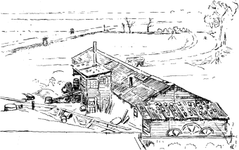
Fig. 6. This is a much reduced reproduction of a drawing made on my studio window in this way some twenty years ago, when the builder started covering the fields at the back with rows and rows of houses.
THE THEORY OF PERSPECTIVE
Definitions
I
Fig. 7. In this figure, AKB represents the picture or transparent vertical plane through which the objects to be represented can be seen, or on which they can be traced, such as the cube C.
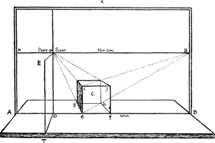
Fig. 7.
The line HD is the Horizontal-line or Horizon, the chief line in perspective, as upon it are placed the principal points to which our perspective lines are drawn. First, the Point of Sight and next D, the Point of Distance. The chief vanishing points and measuring points are also placed on this line.
Another important line is AB, the Base or Ground line, as it is on this that we measure the width of any object to be represented, such as ef, the base of the square efgh, on which the cube C is raised. E is the position of the eye of the spectator, being drawn in perspective, and is called the Station-point.
Note that the perspective of the board, and the line SE, is not AKB, and also that so much of the board which is behind the picture plane partially represents the Perspective-plane, supposed to be perfectly level and to extend from the base line to the horizon. Of this we shall speak further on. In nature it is not really level, but partakes in extended views of the rotundity of the earth, though in small areas such as ponds the roundness is infinitesimal.
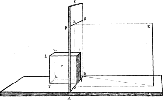
Fig. 8.
Fig. 8. This is a side view of the previous figure, the picture plane K being represented edgeways, and the line SE its full length. It also shows the position of the eye in front of the point of sight S. The horizontal-line HD and the base or ground-line AB are represented as receding from us, and in that case are called vanishing lines, a not quite satisfactory term.
It is to be noted that the cube C is placed close to the transparent picture plane, indeed touches it, and that the square fj faces the spectator E, and although here drawn in perspective it appears to him as in the other figure. Also, it is at the same time a perspective and a geometrical figure, and can therefore be measured with the compasses. Or in other words, we can fj, because it is on the surface of the picture, but we cannot touch the square ghmb at the other end of the cube and can only measure it by the rules of perspective.
II
The Point of Sight, the Horizon, and the Point of Distance
There are three things to be considered and understood before we can begin a perspective drawing. First, the position of the eye in front of the picture, which is called the Station-point, and of course is not in the picture itself, but its position is indicated by a point on the picture which is exactly opposite the eye of the spectator, and is called the Point of Sight, or Principal Point, or Centre of Vision, but we will keep to the first of these.
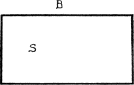
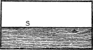
Fig. 9. Fig. 10.
If our picture plane is a sheet of glass, and is so placed that we can see the landscape behind it or a sea-view, we shall find that the distant line of the horizon passes through that point of sight, and we therefore draw a line on our picture which exactly corresponds with it, and which we call the Horizontal-line or Horizon.3 The height of the horizon then depends entirely upon the position of the eye of the spectator: if he rises, so does the horizon; if he stoops or descends to lower ground, so does the horizon follow his movements. You may sit in a boat on a calm sea, and the horizon will be as low down as you are, or you may go to the top of a high cliff, and still the horizon will be on the same level as your eye.
III
Point of Distance
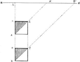
Fig. 11.
Fig. 11. The distance of the spectator from the picture is of great importance; as the distortions and disproportions arising from too near a view are to be avoided, the object of drawing being to make things look natural; thus, the floor should look level, and not as if it were running up hill—the top of a table flat, and not on a slant, as if cups and what not, placed upon it, would fall off.
In this figure we have a geometrical or ground plan of two squares at different distances from the picture, which is represented by the line KK. The spectator is first at A, the corner of the near square Acd. If from A we draw a diagonal of that square and produce it to the line KK (which may represent the horizontal-line in the picture), where it intersects that line at A· marks the distance that the spectator is from the point of sight S. For it will be seen that line SA equals line SA·. In like manner, if the spectator is at B, his distance from the point S is also found on the horizon by means of the diagonal BB´, so that all lines or diagonals at 45° are drawn to the point of distance (see Rule 6).
Figs. 12 and 13. In these two figures the difference is shown between the effect of the short-distance point A· and the long-distance point B·; the first, Acd, does not appear to lie so flat on the ground as the second square, Bef.
From this it will be seen how important it is to choose the
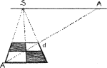
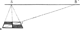
Fig. 12. Fig. 13.
In some books on perspective we are told to make the angle of vision 60°, so that the distance SD (Fig. 14) is to be rather less than the length or height of the picture, as at A. The French recommend an angle of 28°, and to make the distance about double the length of the picture, as at B (Fig. 15), which is far more agreeable. For we must remember that the distance-point is not only the point from which we are supposed to make our tracing on the vertical transparent plane, or a point transferred to the horizon to make our measurements by, but it is also the point in front of the canvas that we view the picture from, called the station-point. It is ridiculous, then, to have it so close that we must almost touch the canvas with our noses before we can see its perspective properly.
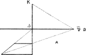
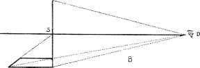
Fig. 14. Fig. 15.
Now a picture should look right from whatever distance we
We need not, however, tie ourselves down to any hard and fast rule, but should choose our distance according to the impression of space we wish to convey: if we have to represent a domestic scene in a small room, as in many Dutch pictures, we must not make our distance-point too far off, as it would exaggerate the size of the room.
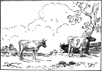
Fig. 16. Cattle. By Paul Potter.
In landscape and cattle pictures a low horizon often gives space and air, as in this sketch from a picture by Paul Potter—where the horizontal-line is placed at one quarter the height of the canvas. Indeed, a judicious use of the laws of perspective is a great aid to composition, and no picture ever looks right unless these laws are attended to. At the present time too little attention is paid to them; the consequence is that much of the art of the day reflects in a great measure the monotony of the snap-shot camera, with its everyday and wearisome commonplace.
IV
Perspective of a Point, Visual Rays, &c.
We perceive objects by means of the visual rays, which are imaginary straight lines drawn from the eye to the various points of the thing we are looking at. As those rays proceed from the pupil of the eye, which is a circular opening, they form themselves into a cone called the Optic Cone, the base of which increases in proportion to its distance from the eye, so that the larger the view which we wish to take in, the farther must we be removed from it. The diameter of the base of this cone, with the visual rays drawn from each of its extremities to the eye, form the angle of vision, which is wider or narrower according to the distance of this diameter.
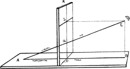
Fig. 17.
Now let us suppose a visual ray EA to be directed to some small object on the floor, say the head of a nail, A (Fig. 17). If we interpose between this nail and our eye a sheet of glass, K, placed vertically on the floor, we continue to see the nail through the glass, and it is easily understood that its perspective appearance thereon is the point a, where the visual ray passes through it. If now we trace on the floor a line AB from the nail to the spot B, just under the eye, and from the point o, where this line passes through or under the glass, we raise a perpendicular oS, that perpendicular passes through the precise point that the visual ray AB traced on the floor is the horizontal trace of the visual ray, and it will be seen that the point a is situated on the vertical raised from this horizontal trace.
V
Trace and Projection
If from any line A or B or C (Fig. 18), &c., we drop perpendiculars from different points of those lines on to a horizontal plane, the intersections of those verticals with the plane will be on a line called the horizontal trace or projection of the original line. We may liken these projections to sun-shadows when the sun is in the meridian, for it will be remarked that the trace does not represent the length of the original line, but only so much of it as would be embraced by the verticals dropped from each end of it, and although line A is the same length as line B its horizontal C) in this upright position is a straight line, that of a horizontal line (D) is equal to it, and the projection of a perpendicular or vertical (E) is a point only. The projections of lines or points can likewise be shown on a vertical plane, but in that case we draw lines parallel to the horizontal plane, and by this means we can get the position of a point in space; and by the assistance of perspective, as will be shown farther on, we can carry out the most difficult propositions of descriptive geometry and of the geometry of planes and solids.
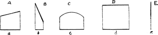
Fig. 18.
The position of a point in space is given by its projection on a vertical and a horizontal plane—
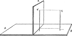
Fig. 19.
Thus e· is the projection of E on the vertical plane K, and e·· is the projection of E on the horizontal plane; fe·· is the horizontal trace of the plane fE, and e·f is the trace of the same plane on the vertical plane K.
VI
Scientific Definition of Perspective
The projections of the extremities of a right line which passes through a vertical plane being given, one on either side of it, to find the intersection of that line with the vertical plane. AE (Fig. 20) is the right line. The projection of its extremity A on the vertical plane is a·, the projection of E, the other extremity, is e·. AS is the horizontal trace of AE, and a·e· is its trace f, where the horizontal trace intersects the base Bc of the vertical plane, raise perpendicular fP till it cuts a·e· at point P, which is the point required. For it is at the same time on the given line AE and the vertical plane K.
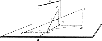
Fig. 20.
This figure is similar to the previous one, except that the extremity A of the given line is raised from the ground, but the same demonstration applies to it.
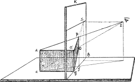
Fig. 21.
And now let us suppose the vertical plane K to be a sheet of glass, and the given line AE to be the visual ray passing from A on the other side of the glass. Then if E is the eye of the spectator, its projection on the picture is S, the point of sight.
If I draw a dotted line from E to little a, this represents another visual ray, and o, the point where it passes through the picture, is the perspective of little a. I now draw another line from g to S, and thus form the shaded figure ga·Po, which is the perspective of aAa·g.
Let it be remarked that in the shaded perspective figure the lines a·P and go are both drawn towards S, the point of sight, and that they represent parallel lines Aa· and ag, which are at right angles to the picture plane. This is the most important fact in perspective, and will be more fully explained farther on, when we speak of retreating or so-called vanishing lines.
RULES
VII
The Rules and Conditions of Perspective
The conditions of linear perspective are somewhat rigid. In the first place, we are supposed to look at objects with one eye only; that is, the visual rays are drawn from a single point, and not from two. Of this we shall speak later on. Then again, the eye must be placed in a certain position, as at E (Fig. 22), at a given height from the ground, S·E, and at a given distance from the picture, as SE. In the next place, the picture or picture plane itself must be vertical and perpendicular to the ground or horizontal plane, which plane is supposed to be as level as a billiard-table, and to extend from the base line, ef, of the picture to the horizon, that is, to infinity, for it does not partake of the rotundity of the earth.
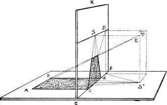
Fig. 22.
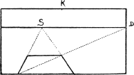
Fig. 23. Front view of above figure.
We can only work out our propositions and figures in space with mathematical precision by adopting such conditions as the above. But afterwards the artist or draughtsman may modify and suit them to a more elastic view of things; that is, he can make his figures separate from one another, instead of their outlines coming close together as they do when we look at them
Rule 1
All straight lines remain straight in their perspective appearance.4
Rule 2
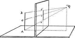
Fig. 24.
Vertical lines remain vertical in perspective, and are divided in the same proportion as AB (Fig. 24), the original line, and a·b·, the perspective line, and if the one is divided at O the other is divided at o· in the same way.
It is not an uncommon error to suppose that the vertical lines of a high building should converge towards the top; so they would if we stood at the foot of that building and looked up, for then we should alter the conditions of our perspective, and our point of sight, instead of being on the horizon, would be up in the sky. But if we stood sufficiently far away, so as to bring the whole of the building within our angle of vision, and the point of sight down to the horizon, then these same lines would appear perfectly parallel, and the different stories in their true proportion.
Rule 3
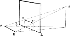
Fig. 25.
Horizontals parallel to the base of the picture are also parallel to that base in the picture. Thus a·b· (Fig. 25) is parallel to AB, GL, the base of the picture. Indeed, the same argument may be used with regard to horizontal lines as with verticals. If we look at a straight wall in front of us, its top and its rows of bricks, &c., are parallel and horizontal; but if we look along it sideways, then we alter the conditions, and the parallel lines converge to whichever point we direct the eye.
This rule is important, as we shall see when we come to the consideration of the perspective vanishing scale. Its use may be illustrated by this sketch, where the houses, walls, &c., are parallel to the base of the picture. When that is the case, then objects
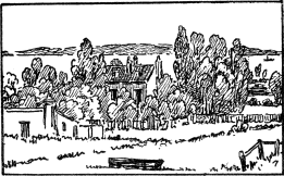
Fig. 26.
Rule 4
All lines situated in a plane that is parallel to the picture plane diminish in proportion as they become more distant, but do not undergo any perspective deformation; and remain in the same relation and proportion each to each as the original lines. This is called the front view.
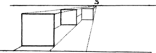
Fig. 27.
Rule 5
All horizontals which are at right angles to the picture plane are drawn to the point of sight.
Thus the lines AB and CD (Fig. 28) are horizontal or parallel to the ground plane, and are also at right angles to the picture plane K. It will be seen that the perspective lines Ba·, Dc·, must, according to the laws of projection, be drawn to the point of sight.
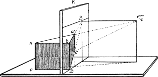
Fig. 28.
This is the most important rule in perspective (see Fig. 7 at beginning of Definitions).
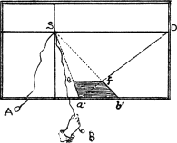
Fig. 29.
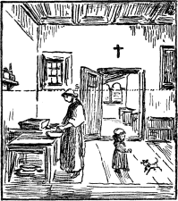
Fig. 30.
An arrangement such as there indicated is the best means of illustrating this rule. But instead of tracing the outline of the square or cube on the glass, as there shown, I have a hole drilled through at the point S (Fig. 29), which I select for the point of sight, and through which I pass two loose strings A and B, fixing their ends at S.
As SD represents the distance the spectator is from the glass or picture, I make string SA equal in length to SD. Now if the pupil takes this string in one hand and holds it at right angles to the glass, that is, exactly in front of S, and then places one eye at the end A (of course with the string extended), he will be at the proper distance from the picture. Let him then take the other string, SB, in the other hand, and apply it to point b´ where the square touches the glass, and he will find that it exactly tallies with the side b´f a·b´fe. If he applies the same string to a·, the other corner of the square, his string will exactly tally or cover the side a·e, and he will thus have ocular demonstration of this important rule.
In this little picture (Fig. 30) in parallel perspective it will be seen that the lines which retreat from us at right angles to the picture plane are directed to the point of sight S.
Rule 6
All horizontals which are at 45°, or half a right angle to the picture plane, are drawn to the point of distance.
We have already seen that the diagonal of the perspective square, if produced to meet the horizon on the picture, will mark on that horizon the distance that the spectator is from the point of sight (see definition, p. 16). This point of distance becomes then the measuring point for all horizontals at right angles to the picture plane.
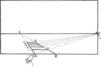
Fig. 31.
AS and BS are drawn to the point of sight S, and are therefore at right angles to the base AB. AD being drawn to D (the distance-point), is at an angle of 45° to the base AB, and AC is therefore the diagonal of a square. The line 1C is made parallel to AB, consequently A1CB is a square in perspective. The line BC, therefore, being one side of that square, is equal to AB, another side of it. So that to measure a length on a line drawn to the point of sight, such as BS, we set out the length required, say BA, on the base-line, then from A draw a line to the point of distance, and where it cuts BS at C is the length required. This can be repeated any number of times, say five, so that in this figure BE is five times the length of AB.
Rule 7
All horizontals forming any other angles but the above are drawn to some other points on the horizontal line. If the angle is greater than half a right angle (Fig. 32), as EBG, the point is within the point of distance, as at V´. If it is less, as ABV´´, then
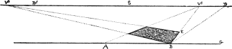
Fig. 32.
In Fig. 32, the dotted line BD, drawn to the point of distance D, is at an angle of 45° to the base AG. It will be seen that the line BV´ is at a greater angle to the base than BD; it is therefore drawn to a point V´, within the point of distance and nearer to the point of sight S. On the other hand, the line BV´´ is at a more acute angle, and is therefore drawn to a point some way beyond the other distance point.
Note.—When this vanishing point is a long way outside the picture, the architects make use of a centrolinead, and the painters fix a long string at the required point, and get their perspective lines by that means, which is very inconvenient. But I will show you later on how you can dispense with this trouble by a very simple means, with equally correct results.
Rule 8
Lines which incline upwards have their vanishing points above the horizontal line, and those which incline downwards, below it. In both cases they are on the vertical which passes through the vanishing point (S) of their horizontal projections.
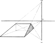
Fig. 33.
This rule is useful in drawing steps, or roads going uphill and downhill.
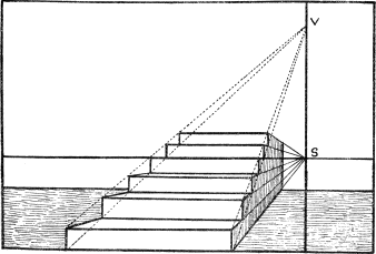
Fig. 34.
Rule 9
The farther a point is removed from the picture plane the nearer does its perspective appearance approach the horizontal line so long as it is viewed from the same position. On the contrary, if the spectator retreats from the picture plane K (which we suppose to be transparent), the point remaining at the same place, the perspective appearance of this point will approach the ground-line in proportion to the distance of the spectator.
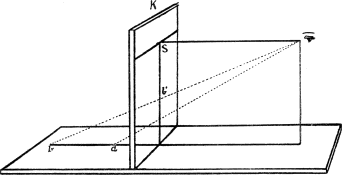
Fig. 35.
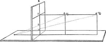
Fig. 36.
The spectator at two different distances from the picture.
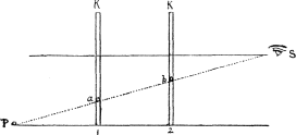
Fig. 37.
Figures 38 and 39 are two views of the same gallery from different distances. In Fig. 38, where the distance is too short, there is a want of proportion between the near and far objects, which is corrected in Fig. 39 by taking a much longer distance.
The picture at two different distances from the point.
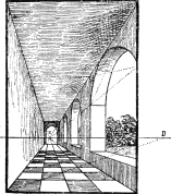
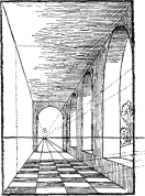
Fig. 38. Fig. 39.
Rule 10
Horizontals in the same plane which are drawn to the same point on the horizon are parallel to each other.
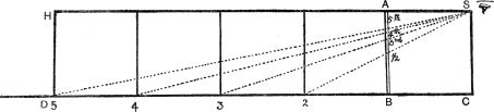
Fig. 40.
This is a very important rule, for all our perspective drawing depends upon it. When we say that parallels are drawn to the same point on the horizon it does not imply that they meet at that point, which would be a contradiction; perspective parallels never reach that point, although they appear to do so. Fig. 40 will explain this.
Suppose S to be the spectator, AB a transparent vertical plane which represents the picture seen edgeways, and HS and DC two parallel lines, mark off spaces between these parallels equal to SC, the height of the eye of the spectator, and raise verticals 2, 3, 4, 5, &c., forming so many squares. Vertical line 2 viewed from S will appear on AB but half its length, vertical 3 will be only a third, vertical 4 a fourth, and so on, and if we multiplied these spaces ad infinitum we must keep on dividing the line AB by the same number. So if we suppose AB to be a yard high and the distance from one vertical to another to be also a yard, then if one of these were a thousand yards away its representation at AB would be the thousandth part of a yard, or ten thousand yards away, its representation at AB would be the ten-thousandth part, and whatever the distance it must always be something; and therefore HS and DC, however far they may be produced
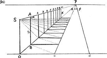
Fig. 41.
Fig. 41 is a perspective view of the same figure—but more extended. It will be seen that a line drawn from the tenth upright K to S cuts off a tenth of AB. We look then upon these two lines SP, OP, as the sides of a long parallelogram of which SK is the diagonal, as cefd, the figure on the ground, is also a parallelogram.
The student can obtain for himself a further illustration of this rule by placing a looking-glass on one of the walls of his studio and then sketching himself and his surroundings as seen therein.
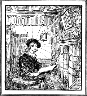
Fig. 42. Sketch of artist in studio.
VIII
A Table or Index of the Rules of Perspective
The rules here set down have been fully explained in the previous pages, and this table is simply for the student's ready reference.
Rule 1
All straight lines remain straight in their perspective appearance.
Rule 2
Vertical lines remain vertical in perspective.
Rule 3
Horizontals parallel to the base of the picture are also parallel to that base in the picture.
Rule 4
All lines situated in a plane that is parallel to the picture plane diminish in proportion as they become more distant, but do not undergo any perspective deformation. This is called the front view.
Rule 5
All horizontal lines which are at right angles to the picture plane are drawn to the point of sight.
Rule 6
All horizontals which are at 45° to the picture plane are drawn to the point of distance.
Rule 7
All horizontals forming any other angles but the above are drawn to some other points on the horizontal line.
Rule 8
Lines which incline upwards have their vanishing points above the horizon, and those which incline downwards, below it. In both cases they are on the vertical which passes through the vanishing point of their ground-plan or horizontal projections.
Rule 9
The farther a point is removed from the picture plane the nearer does it appear to approach the horizon, so long as it is viewed from the same position.
Rule 10
Horizontals in the same plane which are drawn to the same point on the horizon are perspectively parallel to each other.
BOOK SECOND
THE PRACTICE OF PERSPECTIVE
In the foregoing book we have explained the theory or science of perspective; we now have to make use of our knowledge and to apply it to the drawing of figures and the various objects that we wish to depict.
The first of these will be a square with two of its sides parallel to the picture plane and the other two at right angles to it, and which we call
IX
The Square in Parallel Perspective
From a given point on the base line of the picture draw a line at right angles to that base. Let P be the given point on the base line AB, and S the point of sight. We simply draw a line along the ground to the point of sight S, and this line will be at right angles to the base, as explained in Rule 5, and consequently angle APS will be equal to angle SPB, although it does not look so here. This is our first difficulty, but one that we shall soon get over.
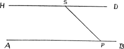
Fig. 43.
P to be placed at so many different positions, our only difficulty being to conceive these lines to be parallel to each other. See Rule 10.
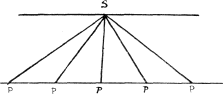
Fig. 44.
X
The Diagonal
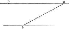
Fig. 45.
From a given point on the base line draw a line at 45°, or half a right angle, to that base. Let P be the given point. Draw a line from P to the point of distance D and this line PD will be at an angle of 45°, or at the same angle as the diagonal of a square. See definitions.
XI
The Square
Draw a square in parallel perspective on a given length on the base line. Let ab be the given length. From its two a and b draw aS and bS to the point of sight S. These two lines will be at right angles to the base (see Fig. 43). From a draw diagonal aD to point of distance D; this line will be 45° to base. At point c, where it cuts bS, draw dc parallel to ab and abcd is the square required.
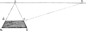
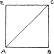
Fig. 46. Fig. 47.
We have here proceeded in much the same way as in drawing a geometrical square (Fig. 47), by drawing two lines AE and BC at right angles to a given line, AB, and from A, drawing the diagonal AC at 45° till it cuts BC at C, and then through C drawing EC parallel to AB. Let it be remarked that because the two perspective lines (Fig. 48) AS and BS are at right angles to the base, they must consequently be parallel to each other, and therefore are perspectively equidistant, so that all lines parallel to AB and lying between them, such as ad, cf, &c., must be equal.
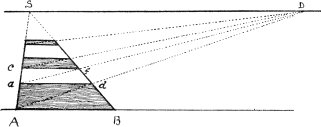
Fig. 48.
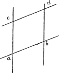
Fig. 49.
So likewise all diagonals drawn to the point of distance, which Ad, af, &c., must be equal. For all straight lines which meet at any point on the horizon are perspectively parallel to each other, just as two geometrical parallels crossing two others at any angle, as at Fig. 49. Note also (Fig. 48) that all squares formed between the two vanishing lines AS, BS, and by the aid of these diagonals, are also equal, and further, that any number of squares such as are shown in this figure (Fig. 50), formed in the same way and having equal bases, are also equal; and the nine squares contained in the square abcd being equal, they divide each side of the larger square into three equal parts.
From this we learn how we can measure any number of given dc, that is, parallel to the base of the picture, however remote it may be from that base.
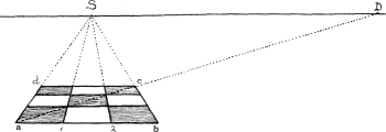
Fig. 50.
XII
Geometrical and Perspective Figures Contrasted
As at first there may be a little difficulty in realizing the resemblance between geometrical and perspective figures, and also about certain expressions we make use of, such as horizontals, perpendiculars, parallels, &c., which look quite different in perspective, I will here make a note of them and also place side by side the two views of the same figures.
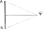
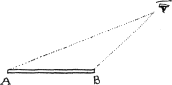
Fig. 51 A. The geometrical view. Fig. 51 B. The perspective view.


Fig. 51 C. A geometrical square. Fig. 51 D. A perspective square.

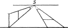
Fig. 51 E. Geometrical parallels. Fig. 51 F. Perspective parallels.

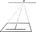
Fig. 51 G. Geometrical perpendicular. Fig. 51 H. Perspective perpendicular.

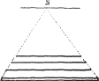
Fig. 51 I. Geometrical equal lines. Fig. 51 J. Perspective equal lines.
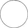
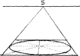
Fig. 51 K. A geometrical circle. Fig. 51 L. A perspective circle.
XIII
Of Certain Terms made use of in Perspective
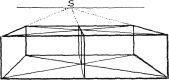
Fig. 52. Horizontals.
Of course when we speak of Perpendiculars we do not mean verticals only, but straight lines at right angles to other lines in any position. Also in speaking of lines a right or straight line is to be understood; or when we speak of horizontals we mean all straight lines that are parallel to the perspective plane, such as those on Fig. 52, no matter what direction they take so long as they are level. They are not to be confused with the horizon or horizontal-line.
There are one or two other terms used in perspective which are not satisfactory because they are confusing, such as vanishing lines and vanishing points. The French term, fuyante or lignes fuyantes, or going-away lines, is more expressive; and point de fuite, instead of vanishing point, is much better. I have occasionally called the former retreating lines, but the simple meaning is, lines that are not parallel to the picture plane; but a vanishing line implies a line that disappears, and a vanishing point implies
XIV
How to Measure Vanishing or Receding Lines
Divide a vanishing line which is at right angles to the picture plane into any number of given measurements. Let SA be the given line. From A measure off on the base line the divisions required, say five of 1 foot each; from each division draw diagonals to point of distance D, and where these intersect the line AC the corresponding divisions will be found. Note that as lines AB and AC are two sides of the same square they are necessarily equal, and so also are the divisions on AC equal to those on AB.
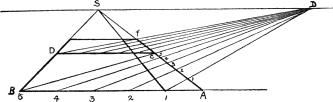
Fig. 53.
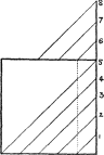
Fig. 54.
The line AB being the base of the picture, it is at the same time a perspective line and a geometrical one, so that we can use it as a scale for measuring given lengths thereon, but should there not be enough room on it to measure the required number we draw a second line, DC, which we divide in the same proportion and proceed to divide cf. This geometrical figure gives, as it were, a bird's-eye view or ground-plan of the above.
XV
How to Place Squares in Given Positions
Draw squares of given dimensions at given distances from the base line to the right or left of the vertical line, which passes through the point of sight.
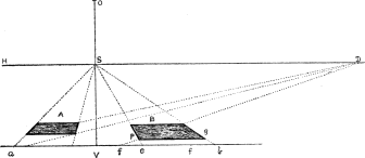
Fig. 55.
Let ab (Fig. 55) represent the base line of the picture divided into a certain number of feet; HD the horizon, VO the vertical. It is required to draw a square 3 feet wide, 2 feet to the right of the vertical, and 1 foot from the base.
First measure from V, 2 feet to e, which gives the distance from the vertical. Second, from e measure 3 feet to b, which gives the width of the square; from e and b draw eS, bS, to point of sight. From either e or b measure 1 foot to the left, to f or f·. Draw fD to point of distance, which intersects eS at P, and gives the required distance from base. Draw Pg and B parallel to the base, and we have the required square.
Square A to the left of the vertical is 2½ feet wide, 1 foot from the vertical and 2 feet from the base, and is worked out in the same way.
Note.—It is necessary to know how to work to scale, especially in architectural drawing, where it is indispensable, but in working
XVI
How To Draw Pavements, &c.
Divide a vanishing line into parts varying in length. Let BS· be the vanishing line: divide it into 4 long and 3 short spaces; then proceed as in the previous figure. If we draw horizontals through the points thus obtained and from these raise verticals, we form, as it were, the interior of a building in which we can place pillars and other objects.
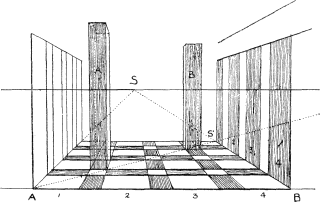
Fig. 56.
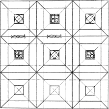
Fig. 57.
And then put it into perspective.
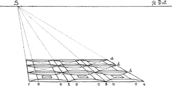
Fig. 58.
XVII
Of Squares placed Vertically and at Different Heights, or the Cube in Parallel Perspective
On a given square raise a cube.
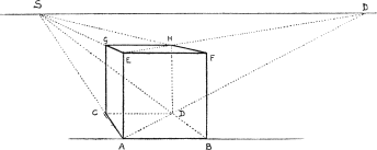
Fig. 59.
ABCD is the given square; from A and B raise verticals AE, BF, equal to AB; join EF. Draw ES, FS, to point of sight; from C and D raise verticals CG, DH, till they meet vanishing lines ES, FS, in G and H, and the cube is complete.
XVIII
The Transposed Distance
The transposed distance is a point D· on the vertical VD·, at exactly the same distance from the point of sight as is the point of distance on the horizontal line.
It will be seen by examining this figure that the diagonals of the squares in a vertical position are drawn to this vertical distance-point, thus saving the necessity of taking the measurements first on the base line, as at CB, which in the case of distant objects, such as the farthest window, would be very inconvenient. Note that the windows at K are twice as high as they are wide.
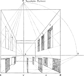
Fig. 60.
XIX
The Front View of the Square and of the Proportions of Figures at Different Heights
According to Rule 4, all lines situated in a plane parallel to the picture plane diminish in length as they become more distant, but remain in the same proportions each to each as the original lines; as squares or any other figures retain the same form. Take the two squares ABCD, abcd (Fig. 61), one inside the other; although moved back from square EFGH they retain the same form. So
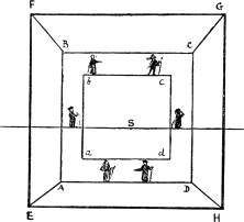
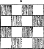
Fig. 61. Fig. 62.
In this square K, with the checker pattern, we should not think of making the top squares smaller than the bottom ones; so it is with figures.
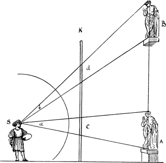
Fig. 63.
In Fig. 63 the two statues A and B are the same size. So if traced through a vertical sheet of glass, K, as at c and d, they would also be equal; but as the angle b at which the upper one is seen is smaller than angle a, at which the lower figure or statue is seen, it will appear smaller to the spectator (S) both in reality and in the picture.
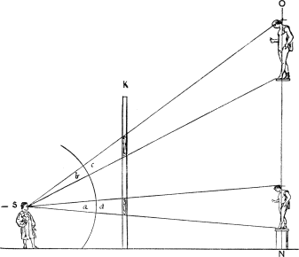
Fig. 64.
But if we wish them to appear the same size to the spectator who is viewing them from below, we must make the angles a and b (Fig. 64), at which they are viewed, both equal. Then draw lines through equal arcs, as at c and d, till they cut the vertical NO (representing the side of the building where the figures are to be placed). We shall then obtain the exact size of the figure at that height, which will make it look the same size as the lower one, N. The same rule applies to the picture K, when it is of large proportions. As an example in painting, take Michelangelo’s large altar-piece in the Sistine Chapel, ‘The Last Judgement’; here the figures forming the upper group, with our Lord in judgement surrounded by saints, are about four times the size, that is, about twice the height, of those at the lower part of the fresco. The
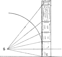
Fig. 65.
Of course, much depends upon the distance we view these statues or paintings from. In interiors, such as churches, halls, galleries, &c., we can make a fair calculation, such as the length of the nave, if the picture is an altar-piece—or say, half the length; so also with statuary in niches, friezes, and other architectural ornaments. The nearer we are to them, and the more we have to look up, the larger will the upper figures have to be; but if these are on the outside of a building that can be looked at from a long distance, then it is better not to have too great a difference.
These remarks apply also to architecture in a great measure. Buildings that can only be seen from the street below, as pictures in a narrow gallery, require a different treatment from those out in the open, that are to be looked at from a distance. In the former case the same treatment as the Campanile at Florence is in some cases desirable, but all must depend upon the taste and judgement of the architect in such matters. All I venture to do here is to call attention to the subject, which seems as a rule to be ignored, or not to be considered of importance. Hence the many mistakes in our buildings, and the unsatisfactory and mean look of some of our public monuments.
XX
Of Pictures that are Painted according to the Position they are to Occupy
In this double-page illustration of the wall of a picture-gallery, I have, as it were, hung the pictures in accordance with the style in which they are painted and the perspective adopted by their painters. It will be seen that those placed on the line level with the eye have their horizon lines fairly high up, and are not suited to be placed any higher. The Giorgione in the centre, the Monna Lisa to the right, and the Velasquez and Watteau to the left, are all pictures that fit that position; whereas the grander compositions above them are so designed, and are so large in conception, that we gain in looking up to them.
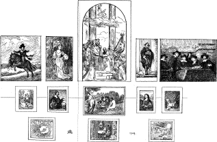
Fig. 66. Larger View
Note how grandly the young prince on his pony, by Velasquez, tells out against the sky, with its low horizon and strong contrast of light and dark; nor does it lose a bit by being placed where it is, over the smaller pictures.
The Rembrandt, on the opposite side, with its burgomasters in black hats and coats and white collars, is evidently intended and painted for a raised position, and to be looked up to, which is evident from the perspective of the table. The grand Titian in
It seems to me it is well, both for those who paint and for those who hang pictures, that this subject should be taken into consideration. For it must be seen by this illustration that a bigger style is adopted by the artists who paint for high places in palaces or churches than by those who produce smaller easel-pictures intended to be seen close. Unfortunately, at our picture exhibitions, we see too often that nearly all the works, whether on large or small canvases, are painted for the line, and that those which happen to get high up look as if they were toppling over, because they have such a high horizontal line; and instead of the figures telling against the sky, as in this picture of the ‘Infant’ by Velasquez, the Reynolds, and the fat man treading on a flag, we have fields or sea or distant landscape almost to the top of the frame, and all, so methinks, because the perspective is not sufficiently considered.
Note.—Whilst on this subject, I may note that the painter in his large decorative work often had difficulties to contend with, which arose from the form of the building or the shape of the wall on which he had to place his frescoes. Painting on the ceiling was no easy task, and Michelangelo, in a humorous sonnet addressed to Giovanni da Pistoya, gives a burlesque portrait of himself while he was painting the Sistine Chapel:—
“I’ho già fatto un gozzo in questo stento.”
Now have I such a goitre ’neath my chin
That I am like to some Lombardic cat,
My beard is in the air, my head i’ my back,
My chest like any harpy’s, and my face
Patched like a carpet by my dripping brush.
Nor can I see, nor can I budge a step;
My skin though loose in front is tight behind,
And I am even as a Syrian bow.
Alas! methinks a bent tube shoots not well;
So give me now thine aid, my Giovanni.
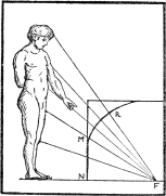
Fig. 67.
‘Draw upon part of wall MN half the figure you mean to represent, and the other half upon the cove above (MR).’ Leonardo da Vinci’s Treatise on Painting.
However, the other difficulty of form has to be got over also. A great portion of the ceiling of the Sistine Chapel, and notably the prophets and sibyls, are painted on a curved surface, in which case a similar method to that explained by Leonardo da Vinci has to be adopted.
In Chapter CCCI he shows us how to draw a figure twenty-four braccia high upon a wall twelve braccia high. (The braccia is 1 ft. 10⅞ in.). He first draws the figure upright, then from the various points draws lines to a point F on the floor of the building, marking their intersections on the profile of the wall somewhat in the manner we have indicated, which serve as guides in making the outline to be traced.
XXI
Interiors
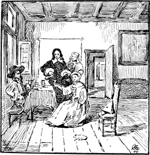
Fig. 68. Interior by de Hoogh.
To draw the interior of a cube we must suppose the side facing us to be removed or transparent. Indeed, in all our figures which represent solids we suppose that we can see through them,
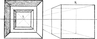
Fig. 69.
When the cube is placed below the horizon (as in Fig. 59), we see the top of it; when on the horizon, as in the above (Fig. 69), if the side facing us is removed we see both top and bottom of it, or if a room, we see floor and ceiling, but otherwise we should see but one side (that facing us), or at most two sides. When the cube is above the horizon we see underneath it.
We shall find this simple cube of great use to us in architectural subjects, such as towers, houses, roofs, interiors of rooms, &c.
In this little picture by de Hoogh we have the application of the perspective of the cube and other foregoing problems.
XXII
The Square at an Angle of 45°
When the square is at an angle of 45° to the base line, then its sides are drawn respectively to the points of distance, DD, and one of its diagonals which is at right angles to the base is drawn to the point of sight S, and the other ab, is parallel to that base or ground line.
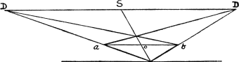
Fig. 70.
To draw a pavement with its squares at this angle is but an amplification of the above figure. Mark off on base equal distances, 1, 2, 3, &c., representing the diagonals of required squares, and from each of these points draw lines to points of distance DD´. These lines will intersect each other, and so form the squares of the pavement; to ensure correctness, lines should also be drawn from these points 1, 2, 3, to the point of sight S, and also horizontals parallel to the base, as ab.
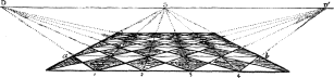
Fig. 71.
XXIII
The Cube at an Angle of 45°
Having drawn the square at an angle of 45°, as shown in the previous figure, we find the length of one of its sides, dh, by drawing a line, SK, through h, one of its extremities, till it cuts the base line at K. Then, with the other extremity d for centre and dK for radius, describe a quarter of a circle Km; the chord thereof mK will be the geometrical length of dh. At d raise vertical dC equal to mK, which gives us the height of the cube, then raise verticals at a, h, &c., their height being found by drawing CD and CD´ to the two points of distance, and so completing the figure.
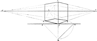
Fig. 72.
XXIV
Pavements Drawn by Means of Squares at 45°
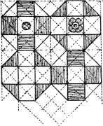
Fig. 75.
The square at 45° will be found of great use in drawing pavements, roofs, ceilings, &c. In Figs. 73, 74 it is shown how 73 and 74, where we have bricks placed at right angles to each other in rows, a common arrangement in brick floors, or tiles of an octagonal form as at Fig. 75.
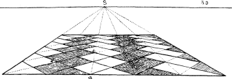
Fig. 73.
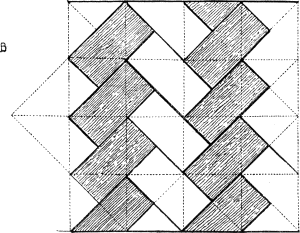
Fig. 74.
XXV
The Perspective Vanishing Scale
The vanishing scale, which we shall find of infinite use in our perspective, is founded on the facts explained in Rule 10. We there find that all horizontals in the same plane, which are drawn to the same point on the horizon, are perspectively parallel to each other, so that if we measure a certain height or width on the picture plane, and then from each extremity draw lines to any convenient point on the horizon, then all the perpendiculars drawn between these lines will be perspectively equal, however much they may appear to vary in length.
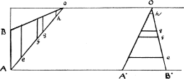
Fig. 76.
Let us suppose that in this figure (76) AB and A·B· each represent 5 feet. Then in the first case all the verticals, as e, f, g, h, drawn between AO and BO represent 5 feet, and in the second case all the horizontals e, f, g, h, drawn between A·O and B·O also represent 5 feet each. So that by the aid of this scale we can give the exact perspective height and width of any object in the picture, however far it may be from the base line, for of course we can increase or diminish our measurements at AB and A·B· to whatever length we require.
As it may not be quite evident at first that the points O may be taken at random, the following figure will prove it.
XXVI
The Vanishing Scale can be Drawn to any Point on the Horizon
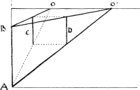
Fig. 77.
From AB (Fig. 77) draw AO, BO, thus forming the scale, raise vertical C. Now form a second scale from AB by drawing AO· BO·, and therein raise vertical D at an equal distance from the base. First, then, vertical C equals AB, and secondly vertical D equals AB, therefore C equals D, so that either of these scales will measure a given height at a given distance.
(See axioms of geometry.)
XXVII
Application of Vanishing Scales to Drawing Figures
In this figure we have marked off on a level plain three or four points a, b, c, d, to indicate the places where we wish to stand our figures. AB represents their average height, so we have made our scale AO, BO, accordingly. From each point marked we draw a line parallel to the base till it reaches the scale. From the point where it touches the line AO, raise perpendicular as a, which gives the height required at that distance, and must be referred back to the figure itself.
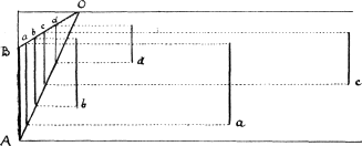
Fig. 78.
XXVIII
How to Determine the Heights of Figures on a Level Plane
First Case.
This is but a repetition of the previous figure, excepting that we have substituted these schoolgirls for the vertical lines. If we wish to make some taller than the others, and some shorter, we can easily do so, as must be evident (see Fig. 79).
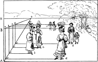
Fig. 79. Schoolgirls.
Note that in this first case the scale is below the horizon, so that we see over the heads of the figures, those nearest to us being the lowest down. That is to say, we are looking on this scene from a slightly raised platform.
Second Case.
To draw figures at different distances when their heads are above the horizon, or as they would appear to a person sitting on a low seat. The height of the heads varies according to the distance of the figures (Fig. 80).
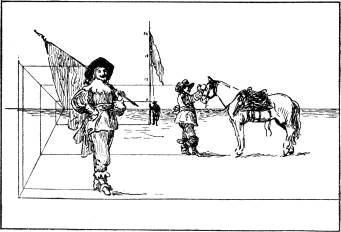
Fig. 80. Cavaliers.
Third Case.
How to draw figures when their heads are about the height of the horizon, or as they appear to a person standing on the same level or walking among them.
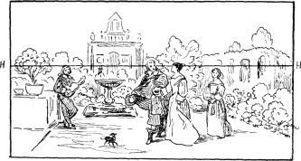
Fig. 81.
In this case the heads or the eyes are on a level with the horizon, and we have little necessity for a scale at the side unless it is for the purpose of ascertaining or marking their distances from the base line, and their respective heights, which of course vary; so in all cases allowance must be made for some being taller and some shorter than the scale measurement.
XXIX
The Horizon above the Figures
In this example from De Hoogh the doorway to the left is higher up than the figure of the lady, and the effect seems to me
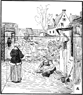
Fig. 82. Courtyard by De Hoogh.
XXX
Landscape Perspective
In an extended view or landscape seen from a height, we have to consider the perspective plane as in a great measure lying above it, reaching from the base of the picture to the horizon; but of course pierced here and there by trees, mountains, buildings, &c. As a rule in such cases, we copy our perspective from nature, and do not trouble ourselves much about mathematical rules. It is as well, however, to know them, so that we may feel sure we are right, as this gives certainty to our touch and enables us to work with freedom. Nor must we, when painting from nature, forget to take into account the effects of atmosphere and the various tones of the different planes of distance, for this makes much of the difference between a good picture and a bad one; being a more subtle quality, it requires a keener artistic sense to discover and depict it. (See Figs. 95 and 103.)
If the landscape painter wishes to test his knowledge of perspective, let him dissect and work out one of Turner's pictures, or better still, put his own sketch from nature to the same test.
XXXI
Figures of Different Heights
The Chessboard
In this figure the same principle is applied as in the previous one, but the chessmen being of different heights we have to arrange the scale accordingly. First ascertain the exact height of each piece, as Q, K, B, which represent the queen, king, bishop, &c. Refer these dimensions to the scale, as shown at QKB, which will give us the perspective measurement of each piece according to the square on which it is placed.
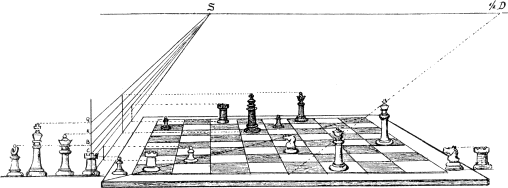
Fig. 83. Chessboard and Men.
C.
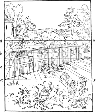
Fig. 84.
XXXII
Application of the Vanishing Scale to Drawing Figures at an Angle when their Vanishing Points are Inaccessible or Outside the Picture
This is exemplified in the drawing of a fence (Fig. 84). Form scale aS, bS, in accordance with the height of the fence or wall to be depicted. Let ao represent the direction or angle at which it is placed, draw od to meet the scale at d, at d raise vertical dc, which gives the height of the fence at oo·. Draw lines bo·, eo, ao, &c., and it will be found that all these lines if produced will meet at the same point on the horizon. To divide the fence into spaces, divide base line af as required and proceed as already shown.
XXXIII
The Reduced Distance. How to Proceed when the Point of Distance is Inaccessible
It has already been shown that too near a point of distance is objectionable on account of the distortion and disproportion resulting from it. At the same time, the long distance-point must be some way out of the picture and therefore inconvenient. The object of the reduced distance is to bring that point within the picture.
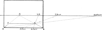
Fig. 85.
In Fig. 85 we have made the distance nearly twice the length of the base of the picture, and consequently a long way out of it. Draw Sa, Sb, and from a draw aD to point of distance, which cuts Sb at o, and determines the depth of the square acob. But o as the other lines aD, &c. We are thus able to find the required point o without going outside the picture.
Of course we could in the same way take an 8th or even a 16th distance, but the great use of this reduced distance, in addition to the above, is that it enables us to measure any depth into the picture with the greatest ease.
It will be seen in the next figure that without having to extend the base, as is usually done, we can multiply that base to any amount by making use of these reduced distances on the horizontal line. This is quite a new method of proceeding, and it will be seen is mathematically correct.
XXXIV
How to Draw a Long Passage or Cloister by means of the Reduced Distance
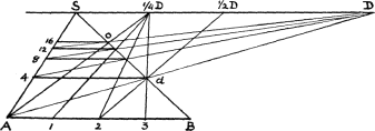
Fig. 86.
In Fig. 86 we have divided the base of the first square into four equal parts, which may represent so many feet, so that A4 and Bd being the retreating sides of the square each represents 4 feet. But we found point ¼ D by drawing 3D from ¼ base to ¼ distance, and by proceeding in the same way from each division, A, 1, 2, 3, we mark off on SB four spaces each equal to 4 feet, in all 16 feet, so that by taking the whole base and the ¼ distance we find point O, which is distant four times the length of the base AB. We can multiply this distance to any amount by drawing other diagonals to 8th distance, &c. The same rule applies to this corridor (Fig. 87 and Fig. 88).
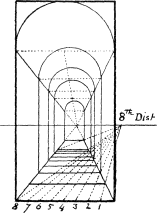
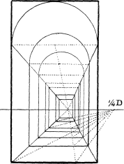
Fig. 87. Fig. 88.
XXXV
How to Form a Vanishing Scale that shall give the Height, Depth, and Distance of any Object in the Picture
If we make our scale to vanish to the point of sight, as in Fig. 89, we can make SB, the lower line thereof, a measuring line for distances. Let us first of all divide the base AB into eight parts, each part representing 5 feet. From each division draw lines to 8th distance; by their intersections with SB we obtain BE in the same manner as the base, which gives us the height of 40 feet. From the side BE draw lines 5S, 15S, &c., to point of sight, and from each division on the base line also draw lines 5S, 10S, 15S, &c., to point of sight, and from each division on SB, such as 40, 80, &c., draw horizontals parallel to base. We thus obtain squares 40 feet wide, beginning at base AB and reaching as far as required. Note how the height of the flagstaff, which is 140 feet high and 280 feet distant, is obtained. So also any buildings or other objects can be measured, such as those shown on the left of the picture.
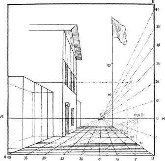
Fig. 89.
XXXVI
Measuring Scale on Ground
A simple and very old method of drawing buildings, &c., and giving them their right width and height is by means of squares of a given size, drawn on the ground.
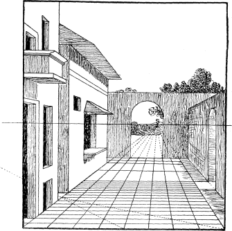
Fig. 90.
In the above sketch (Fig. 90) the squares on the ground
Fig. 91 is a sketch made at Sandwich, Kent, and shows a somewhat similar subject to Fig. 84, but the irregularity and freedom of the perspective gives it a charm far beyond the rigid precision of the other, while it conforms to its main laws. This sketch, however, is the real artist's perspective, or what we might term natural perspective.
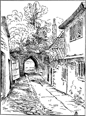
Fig. 91. Natural Perspective.
XXXVII
Application of the Reduced Distance and the Vanishing Scale to Drawing a Lighthouse, &c.
In the drawing of Honfleur (Fig. 92) we divide the base AB as BS measure 40 feet each, and at point O we have 400 feet of distance, but we require 800. So we again reduce the distance to a 16th. We thus multiply the base by 16. Now let us take a base of 50 feet at f and draw line fD to 16th distance; if we multiply 50 feet by 16 we obtain the 800 feet required.
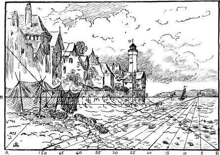
Fig. 92. Honfleur.
The height of the lighthouse is found by means of the vanishing scale, which is 15 feet below and 15 feet above the horizon, or 30 feet from the sea-level. At L we raise a vertical LM, which shows the position of the lighthouse. Then on that vertical measure the height required as shown in the figure.
Perspective of a lighthouse 135 feet high at 800 feet distance.
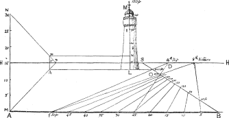
Fig. 93. Key to Fig. 92, Honfleur.
The 800 feet could be obtained at once by drawing line fD, or 50 feet, to 16th distance. The other measurements obtained by 8th distance serve for nearer buildings.
XXXVIII
How to Measure Long Distances such as a Mile or Upwards
The wonderful effect of distance in Turner's pictures is not to be achieved by mere measurement, and indeed can only be properly done by studying Nature and drawing her perspective as she presents it to us. At the same time it is useful to be able to test and to set out distances in arranging a composition. This latter, if neglected, often leads to great difficulties and sometimes to repainting.
To show the method of measuring very long distances we have to work with a very small scale to the foot, and in Fig. 94 I have divided the base AB into eleven parts, each part representing 10 feet. First draw AS and BS to point of sight. A draw AD to ¼ distance, and we obtain at 440 on line BS four times the length of AB, or 110 feet × 4 = 440 feet. Again, taking the whole base and drawing a line from S to 8th distance we obtain eight times 110 feet or 880 feet. If now we use the 16th distance we get sixteen times 110 feet, or 1,760 feet, one-third of a mile; by repeating this process, but by using the base at 1,760, which is the same length in perspective as AB, we obtain 3,520 feet, and then again using the base at 3,520 and proceeding in the same way we obtain 5,280 feet, or one mile to the archway. The flags show their heights at their respective distances from the base. By the scale at the side of the picture, BO, we can measure any height above or any depth below the perspective plane.
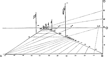
Fig. 94. larger view
Note.—This figure (here much reduced) should be drawn large by the student, so that the numbering, &c., may be made more distinct. Indeed, many of the other figures should be copied large, and worked out with care, as lessons in perspective.
XXXIX
Further Illustration of Long Distances and Extended Views
An extended view is generally taken from an elevated position, so that the principal part of the landscape lies beneath the perspective plane, as already noted, and we shall presently treat of objects and figures on uneven ground. In the previous figure is shown how we can measure heights and depths to any extent. But when we turn to a drawing by Turner, such as the ‘View from Richmond Hill’, we feel that the only way to accomplish such perspective as this, is to go and draw it from nature, and even then to use our judgement, as he did, as to how much we may emphasize or even exaggerate certain features.
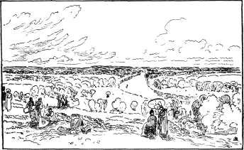
Fig. 95. Turner's View from Richmond Hill.
Note in this view the foreground on which the principal figures stand is on a level with the perspective plane, while the river and surrounding park and woods are hundreds of feet below us
XL
How to Ascertain the Relative Heights of Figures on an Inclined Plane
The three figures to the right marked f, g, b (Fig. 96) are on level ground, and we measure them by the vanishing scale aS, bS. Those to the left, which are repetitions of them, are on an inclined plane, the vanishing point of which is S·; by the side of this plane we have placed another vanishing scale a·S·, b·S·, by which we measure the figures on that incline in the same way as on the level plane. It will be seen that if a horizontal line is drawn from the foot of one of these figures, say G, to point O on the edge of the incline, then dropped vertically to o·, then again carried on to o·· where the other figure g is, we find it is the same height and also that the other vanishing scale is the same width at that distance, so that we can work from either one or the other. In the event of the rising ground being uneven we can make use of the scale on the level plane.
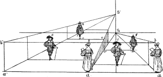
Fig. 96.
XLI
How to Find the Distance of a Given Figure or Point from the Base Line
Let P be the given figure. Form scale ACS, S being the point of sight and D the distance. Draw horizontal do through P. From A draw diagonal AD to distance point, cutting do in o, through o draw SB to base, and we now have a square AdoB on the perspective plane; and as figure P is standing on the far side of that square it must be the distance AB, which is one side of it, from the base line—or picture plane. For figures very far away it might be necessary to make use of half-distance.