Part 3 — CHAPTER XL.
Reading edition
Tesla Direct Current Arc Lighting System.
At one time, soon after his arrival in America, Mr. Tesla was greatly interested in the subject of arc lighting, which then occupied public attention and readily enlisted the support of capital. He therefore worked out a system which was confided to a company formed for its exploitation, and then proceeded to devote his energies to the perfection of the details of his more celebrated "rotary field" motor system. The Tesla arc lighting apparatus appeared at a time when a great many other lamps and machines were in the market, but it commanded notice by its ingenuity. Its chief purpose was to lessen the manufacturing cost and simplify the processes of operation.
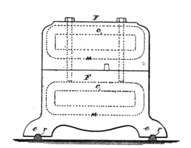
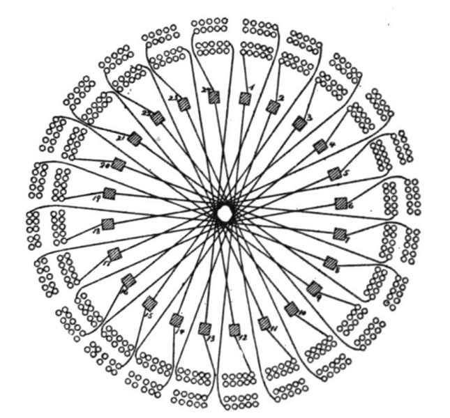
We will take up the dynamo first. Fig. 271 is a longitudinal section, and Fig. 272 a cross section of the machine. Fig. 273 is a top view, and Fig. 274 a side view of the magnetic frame. Fig. 275 is an end view of the commutator bars, and Fig. 276 is a section of the shaft and commutator bars. Fig. 277 is a diagram illustrating the coils of the armature and the connections to the commutator plates.
The cores c c c c of the field-magnets are tapering in both directions, as shown, for the purposes of concentrating the magnetism upon the middle of the pole-pieces.
The connecting-frame F F of the field-magnets is in the form indicated in the side view, Fig. 274, the lower part being provided with the spreading curved cast legs e e, so that the machine will rest firmly upon two base-bars, r r.
To the lower pole, S, of the field-magnet M is fastened, by means of babbitt or other fusible diamagnetic material, the base B, which is provided with bearings b for the armature-shaft H. The base B has a projection, P, which supports the brush-holders and the regulating devices, which are of a special character devised by Mr. Tesla.
The armature is constructed with the view to reduce to a minimum the loss of power due to Foucault currents and to the change of polarity, and also to shorten as much as possible the length of the inactive wire wound upon the armature core.
Fig. 271.
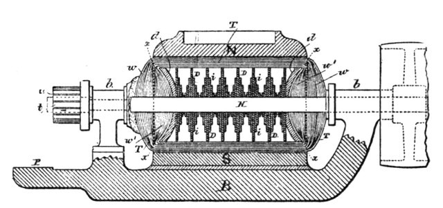
It is well known that when the armature is revolved between the poles of the field-magnets, currents are generated in the iron body of the armature which develop heat, and consequently cause a waste of power. Owing to the mutual action of the lines of force, the magnetic properties of iron, and the speed of the different portions of the armature core, these currents are generated principally on and near the surface of the armature core, diminishing in strength gradually toward the centre of the core. Their quantity is under some conditions proportional to the length of the iron body in the direction in which these currents are generated. By subdividing the iron core electrically in this direction, the generation of these currents can be reduced to a great extent. For instance, if the length of the armature-core is twelve inches, and by a suitable construction it is subdivided electrically, so that there are in the generating direction six inches of iron and six inches of intervening air-spaces or insulating material, the waste currents will be reduced to fifty per cent.
As shown in the diagrams, the armature is constructed of thin iron discs D D D, of various diameters, fastened upon the armature-shaft in a suitable manner and arranged according to their sizes, so that a series of iron bodies, i i i, is formed, each of which diminishes in thickness from the centre toward the periphery. At both ends of the armature the inwardly curved discs d d, of cast iron, are fastened to the armature shaft.
The armature core being constructed as shown, it will be easily seen that on those portions of the armature that are the most remote from the axis, and where the currents are principally developed, the length of iron in the generating direction is only a small fraction of the total length of the armature core, and besides this the iron body is subdivided in the generating direction, and therefore the Foucault currents are greatly reduced. Another cause of heating is the shifting of the poles of the armature core. In consequence of the subdivision of the iron in the armature and the increased surface for radiation, the risk of heating is lessened.
The iron discs D D D are insulated or coated with some insulating-paint, a very careful insulation being unnecessary, as an electrical contact between several discs can only occur at places where the generated currents are comparatively weak. An armature core constructed in the manner described may be revolved between the poles of the field magnets without showing the slightest increase of temperature.
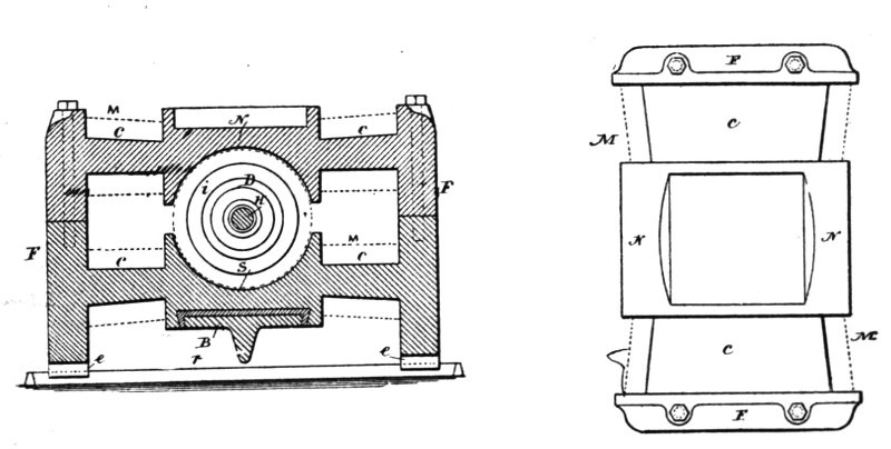
Fig. 272.Fig. 273.
The end discs, d d, which are of sufficient thickness and, for the sake of cheapness, of cast-iron, are curved inwardly, as indicated in the drawings. The extent of the curve is dependent on the amount of wire to be wound upon the armatures. In this machine the wire is wound upon the armature in two superimposed parts, and the curve of the end discs, d d, is so calculated that the first part—that is, practically half of the wire—just fills up the hollow space to the line x x; or, if the wire is wound in any other manner, the curve is such that when the whole of the wire is wound, the outside mass of wires, w, and the inside mass of wires, w', are equal at each side of the plane x x. In this case the passive or electrically-inactive wires are of the smallest length practicable. The arrangement has further the advantage that the total lengths of the crossing wires at the two sides of the plane x x are practically equal.
Fig. 274.
To equalize further the armature coils at both sides of the plates that are in contact with the brushes, the winding and connecting up is effected in the following manner: The whole wire is wound upon the armature-core in two superimposed parts, which are thoroughly insulated from each other. Each of these two parts is composed of three separated groups of coils. The first group of coils of the first part of wire being wound and connected to the commutator-bars in the usual manner, this group is insulated and the second group wound; but the coils of this second group, instead of being connected to the next following commutator bars, are connected to the directly opposite bars of the commutator. The second group is then insulated and the third group wound, the coils of this group being connected to those bars to which they would be connected in the usual way. The wires are then thoroughly insulated and the second part of wire is wound and connected in the same manner.
Suppose, for instance, that there are twenty-four coils—that is, twelve in each part—and consequently twenty-four commutator plates. There will be in each part three groups, each containing four coils, and the coils will be connected as follows:
Groups. Commutator Bars.
First1—5
First part of wireSecond17—21
Third9—13
First13—17
Second part of wire Second 5—9
Third21—1
In constructing the armature core and winding and connecting the coils in the manner indicated, the passive or electrically inactive wire is reduced to a minimum, and the coils at each side of the plates that are in contact with the brushes are practically equal. In this way the electrical efficiency of the machine is increased.
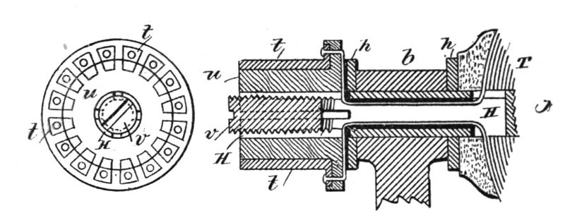
Fig. 275.Fig. 276.
The commutator plates t are shown as outside the bearing b of the armature shaft. The shaft H is tubular and split at the end portion, and the wires are carried through the same in the usual manner and connected to the respective commutator plates. The commutator plates are upon a cylinder, u, and insulated, and this cylinder is properly placed and then secured by expanding the split end of the shaft by a tapering screw plug, v.
Fig. 277.
The arc lamps invented by Mr. Tesla for use on the circuits from the above described dynamo are those in which the separation and feed of the carbon electrodes or their equivalents is accomplished by means of electro-magnets or solenoids in connection with suitable clutch mechanism, and were designed for the purpose of remedying certain faults common to arc lamps.
He proposed to prevent the frequent vibrations of the movable carbon "point" and flickering of the light arising therefrom; to prevent the falling into contact of the carbons; to dispense with the dash pot, clock work, or gearing and similar devices; to render the lamp extremely sensitive, and to feed the carbon almost imperceptibly, and thereby obtain a very steady and uniform light.
In that class of lamps where the regulation of the arc is effected by forces acting in opposition on a free, movable rod or lever directly connected with the electrode, all or some of the forces being dependent on the strength of the current, any change in the electrical condition of the circuit causes a vibration and a corresponding flicker in the light. This difficulty is most apparent when there are only a few lamps in circuit. To lessen this difficulty lamps have been constructed in which the lever or armature, after the establishing of the arc, is kept in a fixed position and cannot vibrate during the feed operation, the feed mechanism acting independently; but in these lamps, when a clamp is employed, it frequently occurs that the carbons come into contact and the light is momentarily extinguished, and frequently parts of the circuit are injured. In both these classes of lamps it has been customary to use dash pot, clock work, or equivalent retarding devices; but these are often unreliable and objectionable, and increase the cost of construction.
Mr. Tesla combines two electro-magnets—one of low resistance in the main or lamp circuit, and the other of comparatively high resistance in a shunt around the arc—a movable armature lever, and a special feed mechanism, the parts being arranged so that in the normal working position of the armature lever the same is kept almost rigidly in one position, and is not affected even by considerable changes in the electric circuit; but if the carbons fall into contact the armature will be actuated by the magnets so as to move the lever and start the arc, and hold the carbons until the arc lengthens and the armature lever returns to the normal position. After this the carbon rod holder is released by the action of the feed mechanism, so as to feed the carbon and restore the arc to its normal length.
Fig. 278 is an elevation of the mechanism made use of in this arc lamp. Fig. 279 is a plan view. Fig. 280 is an elevation of the balancing lever and spring; Fig. 281 is a detached plan view of the pole pieces and armatures upon the friction clamp, and Fig. 282 is a section of the clamping tube.
M is a helix of coarse wire in a circuit from the lower carbon holder to the negative binding screw −. N is a helix of fine wire in a shunt between the positive binding screw + and the negative binding screw −. The upper carbon holder S is a parallel rod sliding through the plates S' S2 of the frame of the lamp, and hence the electric current passes from the positive binding post + through the plate S2, carbon holder S, and upper carbon to the lower carbon, and thence by the holder and a metallic connection to the helix M.
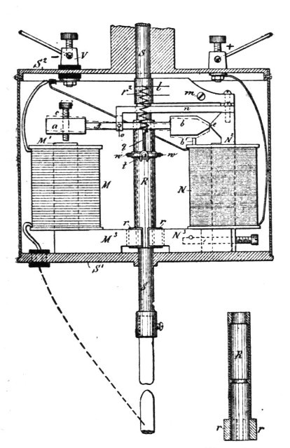
Fig. 278.Fig. 282.
Fig. 279.
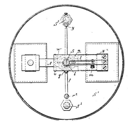
Fig. 280.
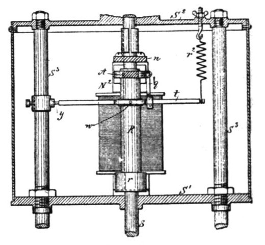
Fig. 281.
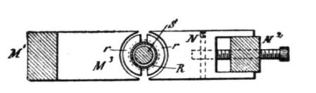
The carbon holders are of the usual character, and to insure electric connections the springs l are made use of to grasp the upper carbon holding rod S, but to allow the rod to slide freely through the same. These springs l may be adjusted in their pressure by the screw m, and the spring l maybe sustained upon any suitable support. They are shown as connected with the upper end of the core of the magnet N.
Around the carbon-holding rod S, between the plates S' S2, there is a tube, R, which forms a clamp. This tube is counter-bored, as seen in the section Fig. 282, so that it bears upon the rod S at its upper end and near the middle, and at the lower end of this tubular clamp R there are armature segments r of soft iron. A frame or arm, n, extending, preferably, from the core N2, supports the lever A by a fulcrum-pin, o. This lever A has a hole, through which the upper end of the tubular clamp R passes freely, and from the lever A is a link, q, to the lever t, which lever is pivoted at y to a ring upon one of the columns S3. This lever t has an opening or bow surrounding the tubular clamp R, and there are pins or pivotal connections w between the lever t and this clamp R, and a spring, r2, serves to support or suspend the weight of the parts and balance them, or nearly so. This spring is adjustable.
At one end of the lever A is a soft-iron armature block, a, over the core M' of the helix M, and there is a limiting screw, c, passing through this armature block a, and at the other end of the lever A is a soft iron armature block, b, with the end tapering or wedge shaped, and the same comes close to and in line with the lateral projection e on the core N2. The lower ends of the cores M' N2 are made with laterally projecting pole-pieces M3 N3, respectively, and these pole-pieces are concave at their outer ends, and are at opposite sides of the armature segments r at the lower end of the tubular clamp R.
The operation of these devices is as follows: In the condition of inaction, the upper carbon rests upon the lower one, and when the electric current is turned on it passes freely, by the frame and spring l, through the rods and carbons to the coarse wire and helix M, and to the negative binding post V and the core M' thereby is energized. The pole piece M3 attracts the armature r, and by the lateral pressure causes the clamp R to grasp the rod S', and the lever A is simultaneously moved from the position shown by dotted lines, Fig. 278, to the normal position shown in full lines, and in so doing the link q and lever t are raised, lifting the clamp R and S, separating the carbons and forming the arc. The magnetism of the pole piece e tends to hold the lever A level, or nearly so, the core N2 being energized by the current in the shunt which contains the helix N. In this position the lever A is not moved by any ordinary variation in the current, because the armature b is strongly attracted by the magnetism of e, and these parts are close to each other, and the magnetism of e acts at right angles to the magnetism of the core M'. If, now, the arc becomes too long, the current through the helix M is lessened, and the magnetism of the core N3 is increased by the greater current passing through the shunt, and this core N3, attracting the segmental armature r, lessens the hold of the clamp R upon the rod S, allowing the latter to slide and lessen the length of the arc, which instantly restores the magnetic equilibrium and causes the clamp R to hold the rod S. If it happens that the carbons fall into contact, then the magnetism of N2 is lessened so much that the attraction of the magnet M will be sufficient to move the armature a and lever A so that the armature b passes above the normal position, so as to separate the carbons instantly; but when the carbons burn away, a greater amount of current will pass through the shunt until the attraction of the core N2 will overcome the attraction of the core M' and bring the armature lever A again into the normal horizontal position, and this occurs before the feed can take place. The segmental armature pieces r are shown as nearly semicircular. They are square or of any other desired shape, the ends of the pole pieces M3, N3 being made to correspond in shape.
In a modification of this lamp, Mr. Tesla provided means for automatically withdrawing a lamp from the circuit, or cutting it out when, from a failure of the feed, the arc reached an abnormal length; and also means for automatically reinserting such lamp in the circuit when the rod drops and the carbons come into contact.
Fig. 283 is an elevation of the lamp with the case in section. Fig. 284 is a sectional plan at the line x x. Fig. 285 is an elevation, partly in section, of the lamp at right angles to Fig. 283. Fig. 286 is a sectional plan at the line y y of Fig. 283. Fig. 287 is a section of the clamp in about full size. Fig. 288 is a detached section illustrating the connection of the spring to the lever that carries the pivots of the clamp, and Fig. 289 is a diagram showing the circuit-connections of the lamp.
In Fig. 283, M represents the main and N the shunt magnet, both securely fastened to the base A, which with its side columns, S S, are cast in one piece of brass or other diamagnetic material. To the magnets are soldered or otherwise fastened the brass washers or discs a a a a. Similar washers, b b, of fibre or other insulating material, serve to insulate the wires from the brass washers.
The magnets M and N are made very flat, so that their width exceeds three times their thickness, or even more. In this way a comparatively small number of convolutions is sufficient to produce the required magnetism, while a greater surface is offered for cooling off the wires.
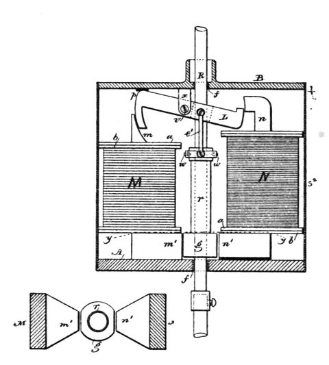
Fig. 286.Fig. 283.
Fig. 285.
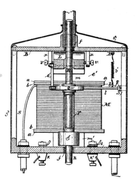
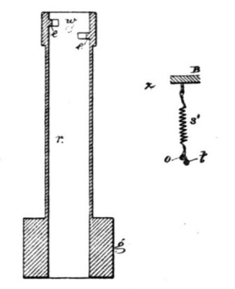
Fig. 287.Fig. 288.
Fig. 284.
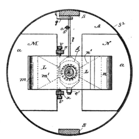
The upper pole pieces, m n, of the magnets are curved, as indicated in the drawings, Fig. 283. The lower pole pieces m' n', are brought near together, tapering toward the armature g, as shown in Figs. 284 and 286. The object of this taper is to concentrate the greatest amount of the developed magnetism upon the armature, and also to allow the pull to be exerted always upon the middle of the armature g. This armature g is a piece of iron in the shape of a hollow cylinder, having on each side a segment cut away, the width of which is equal to the width of the pole pieces m' n'.
The armature is soldered or otherwise fastened to the clamp r, which is formed of a brass tube, provided with gripping-jaws e e, Fig. 287. These jaws are arcs of a circle of the diameter of the rod R, and are made of hardened German silver. The guides f f, through which the carbon-holding rod R slides, are made of the same material. This has the advantage of reducing greatly the wear and corrosion of the parts coming in frictional contact with the rod, which frequently causes trouble. The jaws e e are fastened to the inside of the tube r, so that one is a little lower than the other. The object of this is to provide a greater opening for the passage of the rod when the same is released by the clamp. The clamp r is supported on bearings w w, Figs. 283, 285 and 287, which are just in the middle between the jaws e e. The bearings w w are carried by a lever, t, one end of which rests upon an adjustable support, q, of the side columns, S, the other end being connected by means of the link e' to the armature-lever L. The armature-lever L is a flat piece of iron in N shape, having its ends curved so as to correspond to the form of the upper pole-pieces of the magnets M and N. It is hung upon the pivots v v, Fig. 284, which are in the jaw x of the top plate B. This plate B, with the jaw, is cast in one piece and screwed to the side columns, S S, that extend up from the base A. To partly balance the overweight of the moving parts, a spring, s', Figs. 284 and 288, is fastened to the top plate, B, and hooked to the lever t. The hook o is toward one side of the lever or bent a little sidewise, as seen in Fig. 288. By this means a slight tendency is given to swing the armature toward the pole-piece m' of the main magnet.
The binding-posts K K' are screwed to the base A. A manual switch, for short-circuiting the lamp when the carbons are renewed, is also fastened to the base. This switch is of ordinary character, and is not shown in the drawings.
The rod R is electrically connected to the lamp-frame by means of a flexible conductor or otherwise. The lamp-case receives a removable cover, s2, to inclose the parts.
The electrical connections are as indicated diagrammatically in Fig. 289. The wire in the main magnet consists of two parts, x' and p'. These two parts may be in two separated coils or in one single helix, as shown in the drawings. The part x' being normally in circuit, is, with the fine wire upon the shunt-magnet, wound and traversed by the current in the same direction, so as to tend to produce similar poles, N N or S S, on the corresponding pole-pieces of the magnets M and N. The part p' is only in circuit when the lamp is cut out, and then the current being in the opposite direction produces in the main magnet, magnetism of the opposite polarity.
The operation is as follows: At the start the carbons are to be in contact, and the current passes from the positive binding-post K to the lamp-frame, carbon-holder, upper and lower carbon, insulated return-wire in one of the side rods, and from there through the part x' of the wire on the main magnet to the negative binding-post. Upon the passage of the current the main magnet is energized and attracts the clamping-armature g, swinging the clamp and gripping the rod by means of the gripping jaws e e. At the same time the armature lever L is pulled down and the carbons are separated. In pulling down the armature lever L the main magnet is assisted by the shunt-magnet N, the latter being magnetized by magnetic induction from the magnet M.
Fig. 289.
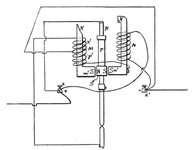
It will be seen that the armatures L and g are practically the keepers for the magnets M and N, and owing to this fact both magnets with either one of the armatures L and g may be considered as one horseshoe magnet, which we might term a "compound magnet." The whole of the soft-iron parts M, m', g, n', N and L form a compound magnet.
The carbons being separated, the fine wire receives a portion of the current. Now, the magnetic induction from the magnet M is such as to produce opposite poles on the corresponding ends of the magnet N; but the current traversing the helices tends to produce similar poles on the corresponding ends of both magnets, and therefore as soon as the fine wire is traversed by sufficient current the magnetism of the whole compound magnet is diminished.
With regard to the armature g and the operation of the lamp, the pole m' may be considered as the "clamping" and the pole n' as the "releasing" pole.
As the carbons burn away, the fine wire receives more current and the magnetism diminishes in proportion. This causes the armature lever L to swing and the armature g to descend gradually under the weight of the moving parts until the end p, Fig. 283, strikes a stop on the top plate, B. The adjustment is such that when this takes place the rod R is yet gripped securely by the jaws e e. The further downward movement of the armature lever being prevented, the arc becomes longer as the carbons are consumed, and the compound magnet is weakened more and more until the clamping armature g releases the hold of the gripping-jaws e e upon the rod R, and the rod is allowed to drop a little, thus shortening the arc. The fine wire now receiving less current, the magnetism increases, and the rod is clamped again and slightly raised, if necessary. This clamping and releasing of the rod continues until the carbons are consumed. In practice the feed is so sensitive that for the greatest part of the time the movement of the rod cannot be detected without some actual measurement. During the normal operation of the lamp the armature lever L remains practically stationary, in the position shown in Fig. 283.
Should it happen that, owing to an imperfection in it, the rod and the carbons drop too far, so as to make the arc too short, or even bring the carbons in contact, a very small amount of current passes through the fine wire, and the compound magnet becomes sufficiently strong to act as at the start in pulling the armature lever L down and separating the carbons to a greater distance.
It occurs often in practical work that the rod sticks in the guides. In this case the are reaches a great length, until it finally breaks. Then the light goes out, and frequently the fine wire is injured. To prevent such an accident Mr. Tesla provides this lamp with an automatic cut-out which operates as follows: When, upon a failure of the feed, the arc reaches a certain predetermined length, such an amount of current is diverted through the fine wire that the polarity of the compound magnet is reversed. The clamping armature g is now moved against the shunt magnet N until it strikes the releasing pole n'. As soon as the contact is established, the current passes from the positive binding post over the clamp r, armature g, insulated shunt magnet, and the helix p' upon the main magnet M to the negative binding post. In this case the current passes in the opposite direction and changes the polarity of the magnet M, at the same time maintaining by magnetic induction in the core of the shunt magnet the required magnetism without reversal of polarity, and the armature g remains against the shunt magnet pole n'. The lamp is thus cut out as long as the carbons are separated. The cut out may be used in this form without any further improvement; but Mr. Tesla arranges it so that if the rod drops and the carbons come in contact the arc is started again. For this purpose he proportions the resistance of part p' and the number of the convolutions of the wire upon the main magnet so that when the carbons come in contact a sufficient amount of current is diverted through the carbons and the part x' to destroy or neutralize the magnetism of the compound magnet. Then the armature g, having a slight tendency to approach to the clamping pole m', comes out of contact with the releasing pole n'. As soon as this happens, the current through the part p' is interrupted, and the whole current passes through the part x. The magnet M is now strongly magnetized, the armature g is attracted, and the rod clamped. At the same time the armature lever L is pulled down out of its normal position and the arc started. In this way the lamp cuts itself out automatically when the arc gets too long, and reinserts itself automatically in the circuit if the carbons drop together.