SUPPLEMENT Models, in the National Museum, of Locomotives Not Included in This Work
Reading edition
Certain of the locomotives, locomotive parts, and models described in the foregoing pages have been noted as being in the collection of the United States National Museum. In addition to these, the collection of the Museum includes 21 models of locomotives that do not fall into the scope of this work, as the originals they represent are either no longer in existence, are of too recent vintage, or were not used in North America. Among them are five operable models—four steam and one electric.
The originals represented by many of these models were involved in notable events in the history of railroading or mark major steps in its progress. For these reasons, and in order to provide the reader with a complete catalog of the locomotive collection of the United States National Museum, a brief description of each will be given on the pages that follow.
76
Trevithick Locomotive, 1804
The National Museum’s nonoperable model shown in figure 61 represents the probable form of the first rail locomotive of Richard Trevithick, the Cornish engineer who was one of the early advocates of the high-pressure steam engine. The Museum’s model (USNM 180058) is about 20 inches in length, and its flywheel is about 10 inches in diameter. It was obtained in 1888 from its builder D. Ballauf, a model maker often employed by the Museum.
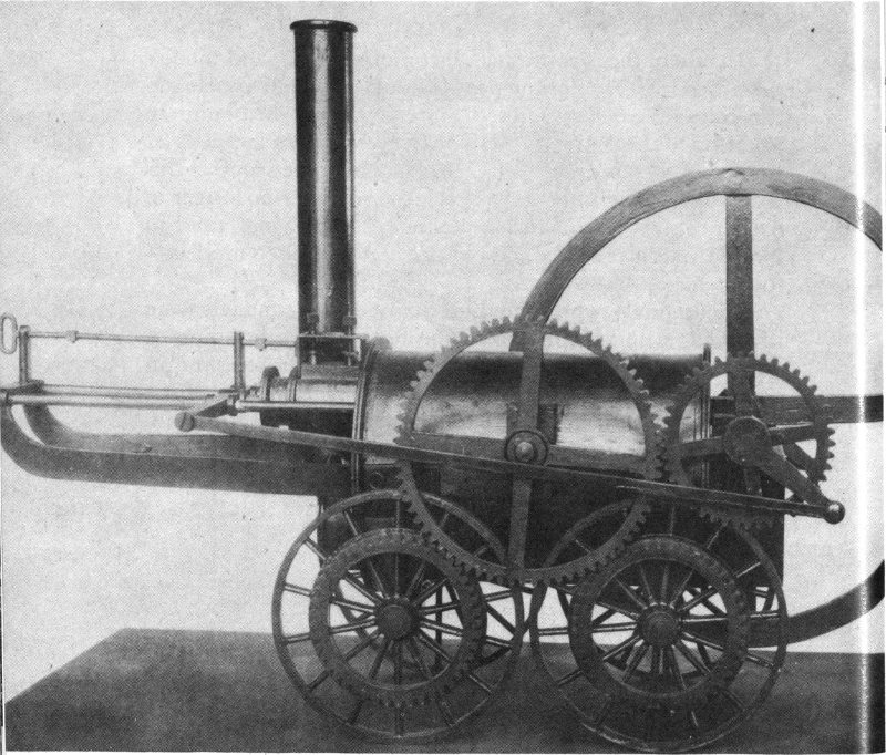
Figure 61.—Model of Trevithick locomotive, 1804.
77
Trevithick, who a few years earlier had constructed several successful steam vehicles for use on the highways, in February 1804 completed the construction of a machine at Pen-y-darran, near Merthyr Tydfil, Glamorganshire, Wales, for use at the Pen-y-darran Iron Works of Samuel Homfray. It is thought to have been the first steam locomotive ever propelled along a railway.
The first trip was made on Monday, February 13, 1804. Among the several trips made by the locomotive was one of 9 miles, between Merthyr Tydfil and Abercynon, drawing 5 cars with a load of 10 tons of iron and 70 men. Although a satisfactory machine, and one that proved that a useful load could be hauled through the adhesion of wheels on smooth track, it was not long in use because of frequent breakage of the primitive railway.
The single horizontal steam cylinder, projecting partly into the end of the boiler, operated a crankshaft fitted with a large-diameter flywheel. The driving wheels were coupled to the crankshaft by gearing. The bore and stroke of the cylinder are said to have been about 8¼ and 54 inches, respectively, and the unflanged wheels were about 45 inches in diameter. Discharge of the exhaust steam into the chimney was utilized with this particular locomotive, as Trevithick appreciated fully the effect it had upon the fire. The date of this early use of exhaust steam to aid the fire greatly antedates those claimed for later locomotive builders.
Trevithick Locomotive Catch-me-who-can, 1808
Trevithick’s next best known locomotive, his Catch-me-who-can, is represented in the national collection by a 9-inch-long nonoperable model (USNM 244889). The model (figure 62) was transferred to the Museum from the U. S. Department of the Interior in 1906. Nothing further is known of its origin.
The original Catch-me-who-can, built for Trevithick by Hazeldine and Rastrick of Bridgnorth, was exhibited in the summer of 1808 in London on a small circular railway laid down on part of the ground now occupied by Euston Square. The public was charged admission to enter a small enclosure 78 to view the demonstration or ride in a small car pulled by the locomotive.
As on his 1804 locomotive, a single cylinder projecting partly within the end of the boiler was used, but it was vertical instead of horizontal. The rear wheels only were driven, actuated by long, return connecting rods attached to the ends of a wide crosshead. Because of the necessary arrangement of the cranks on the ends of the rear axle, it was entirely possible for the engine to stop on dead center. This was likewise a fault of the 1804 locomotive, which had a single crank.
The engine is said to have weighed 8 tons and to have traveled at a speed of 12 miles an hour, but troubles with the track ultimately brought the demonstrations to a halt. No dimensions are known today of the original Catch-me-who-can, which has long since disappeared.
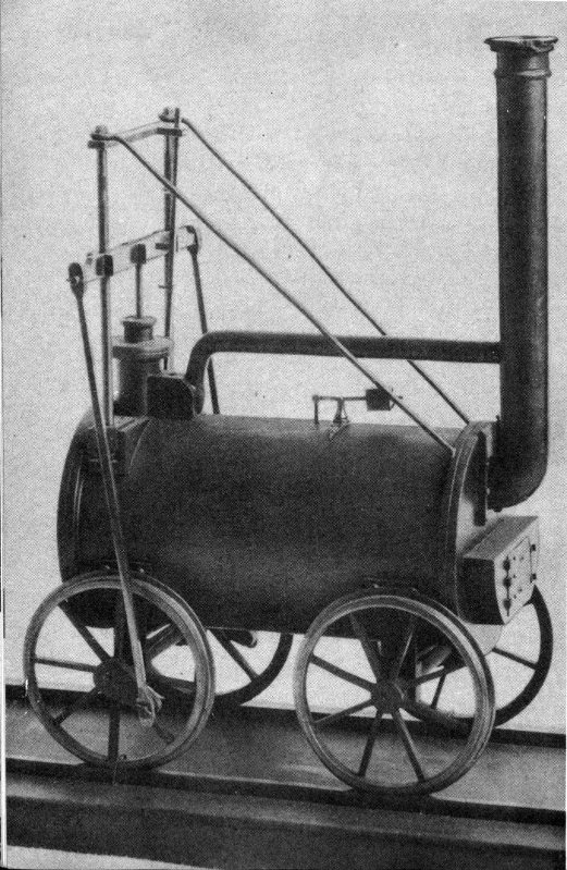
Figure 62.—Model of Trevithick Catch-me-who-can, 1808.
79
Stephenson Locomotive Rocket, 1829
Probably the most famous of Robert Stephenson’s many locomotives, the Rocket, winner of the Rainhill Trials in October 1829, is represented in the Museum collection by a nonoperable model (figure 63) that, with its tender, is a little less than 1½ feet long. The model was transferred to the Museum (USNM 244890) from the U. S. Department of the Interior in 1906.
The original Rocket, the considerably altered remains of which now appear on exhibition in the Science Museum at South Kensington, was constructed by Stephenson at Newcastle-upon-Tyne to compete for the £500 prize offered by the Liverpool and Manchester Railway. The Rocket turned out to be the only one of the five competing machines to finish the trials. Its success was especially important because it showed beyond doubt that steam locomotives were suitable for general railway work, and also because they could attain speeds not previously known. Running with a light load, it reached a speed of 29 miles an hour.
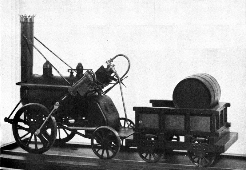
Figure 63.—Model of Stephenson Rocket, 1829.
The locomotive weighed 3¼ tons empty and 4¼ tons in working order. It had two inclined cylinders of 8-inch bore 80 and 17-inch stroke and two 56½-inch-diameter driving wheels at the front. A tubular boiler suggested by Henry Booth, the secretary and treasurer of the Liverpool and Manchester Railway, is said to have contributed greatly to the success of the Rocket during the trials. It must not be forgotten, however, that in America John Stevens had used successfully a tubular boiler in his experimental locomotive in 1825.
The Rocket was used on the Liverpool and Manchester Railway until 1836, and from then until 1844 on the Midgeholme Railway near Carlisle. It was presented to the Science Museum in 1862, where it is now an outstanding exhibit in the railroad collection.
J. G. H. Warren’s history of Robert Stephenson & Co., which contains detailed and well illustrated accounts of the Rocket and of the Rainhill Trials, will interest those seeking further details on either subject.
Baldwin Locomotive Old Ironsides, 1832
The locomotive Old Ironsides is represented in the Museum’s collection by a nonoperable model (figure 64) that, with its tender, is 3 feet long. The model (USNM 180114) was given to the Museum in 1889 by Burnham, Parry, Williams & Co., who were then proprietors of the Baldwin Locomotive Works.
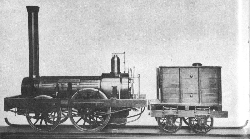
Figure 64.—Model of Baldwin Old Ironsides, 1832.
81
The original Old Ironsides was the first full sized locomotive built by Matthias W. Baldwin, a jeweler turned machinist, of Philadelphia. It was constructed for the Philadelphia, Germantown, and Norristown Rail-Road Co., which had been using horse cars in operating a short line of only 6 miles between Philadelphia and Germantown.
The line’s first locomotive, Old Ironsides, was initially operated on the road on November 23, 1832, and was a success from the start, though a few understandable imperfections were noted during the trials and shortly corrected. The fairly new locomotive John Bull of the Camden and Amboy Rail Road and Transportation Co. had been inspected by Baldwin before he undertook the project. Undoubtedly it furnished helpful suggestions to the man whose locomotive building enterprise was ultimately to eclipse anything possibly dreamed of by him.
The locomotive, contracted for at $4,000 but for which Baldwin was, after some difficulty, able to collect only $3,500, was somewhat similar to the locomotives of the English Planet class quite popular at the time. The two driving wheels, located at the rear, were larger than the carrying ones at the front, the diameters being 54 and 45 inches, respectively. The two cylinders had a bore of 9½ inches and a stroke of 18. The exhaust steam was discharged into the chimney in order to increase the draft. The boiler, 30 inches in diameter, contained 72 copper tubes 1½ inches in diameter and 7 feet long.
A complete description of Old Ironsides and detailed accounts of its first trials are to be found in “History of the Baldwin Locomotive Works, 1831-1923.”
Davis and Gartner Locomotive Arabian, 1834
Davis and Gartner, who built the Atlantic in 1832 for the Baltimore and Ohio Rail Road (see p. 47), built as their next two “grasshoppers” the Traveller and the Arabian. The latter of these was placed in service on the B & O in July 1834. Neither of these two locomotives is extant, but a 2-foot-long nonoperable model of the Arabian (figure 65) is now in 82 the National Museum collection (USNM 233511). It was made in the Museum in about 1900 by C. R. Luscombe.
The Arabian was similar in design to the three “grasshoppers” that have survived, but differed from them in many small ways. Its two cylinders, for example, had a bore and stroke of 12 and 22 inches. This bore was fractionally less than that of the other three. Also, its weight with fuel and water, 7½ tons, was about a ton less than that of any of the others.
The extent to which the Museum’s model represents these slight differences between the Arabian and the “grasshoppers” that followed it cannot now be determined. Most of these differences would be impossible to reproduce on such a small scale. It is entirely possible that the model represented no particular “grasshopper,” and the name Arabian may have been selected by chance.
A detailed description of the construction of the Arabian and a discussion of its performance characteristics appear in the eighth (1834) and ninth (1835) annual reports of the Baltimore and Ohio Rail Road Co.
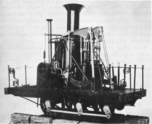
Figure 65.—Model of Davis and Gartner Arabian, 1834.
83
Rogers, Ketchum & Grosvenor Locomotive Sandusky, 1837
The Sandusky, first locomotive built by the firm of Rogers, Ketchum & Grosvenor of Paterson, N. J., is represented in the Museum’s collection by a 2-foot-long nonoperable model (figure 66) of the locomotive and its tender. The model (USNM 180245) was built for the Museum in 1888 by D. Ballauf.
Notice of the firm’s intention to produce locomotives was given in the “American Railroad Journal” for December 24, 1836, and the original Sandusky was constructed during the following year. Intended for the New Jersey Railroad and Transportation Co., it was built to the gauge of that road—58 inches. However, after a trial trip on October 6 between Paterson and New Brunswick, it was purchased for the Mad River and Lake Erie Railroad by that road’s president, J. H. James of Urbana, Ohio.
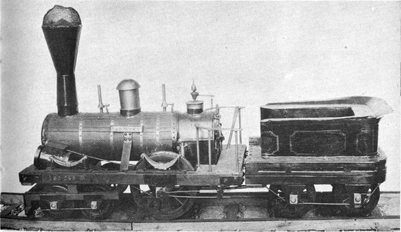
Figure 66.—Model of Rogers, Ketchum & Grosvenor Sandusky, 1837.
It was delivered to Sandusky, Ohio, on November 17, at which time not a foot of track had been laid. The engine was used in the construction of the road, which in consequence 84 was built to the gauge of the engine. This fact has been given as the reason why the legislature of Ohio at one time passed an act requiring all railroads built in Ohio to be of 58-inch gauge. On April 11, 1838, regular trips for the conveyance of passengers commenced between Bellevue and Sandusky, a distance of 16 miles, and the locomotive Sandusky was used.
The Sandusky resembled the early Stephenson engines in some respects, but differed principally in having a 4-wheeled leading truck, the wheels of which were 30 inches in diameter. The two driving wheels, made of cast iron and with hollow spokes and rims, were 54 inches in diameter. The crankshaft throws were counterbalanced by a method of balancing devised by Thomas Rogers, who had filed a patent application on it dated July 12, 1837. This consisted of having the part of the wheel rim opposite the crank throw cast solid, while the rest of the rim was hollow.
The driving wheels and the inclined 11- by 16-inch cylinders were inside the frame, whereas the eccentric rods, working off the outer ends of the driving axle, were outside. The bonnet-type smokestack had a deflecting cone in its center and a wire mesh on the top to prevent the escape of sparks.
Rogers, Ketchum & Grosvenor Locomotive General, 1855
The smallest locomotive model in the National Museum (figure 67) is of the wood-burning locomotive General that figured so prominently in the famous Civil War locomotive chase of April 12, 1862. (In William Pittenger’s “The Great Locomotive Chase” is told the complete story of this epic adventure, which took place when a group of Northern raiders stole the General and its train at Big Shanty, Ga. The Confederates finally recaptured the General minus the cars, which had been cut loose to delay the pursuers, but with most of the raiders, after a thrilling pursuit that led them 90 miles away, to Ringgold, Ga., just south of Chattanooga, Tenn.)
The Museum’s display is constructed from a pair of model kits, to which a great many engineering details have been 85 added. It shows two beautifully made reproductions, scaled ⅛ inch to the foot, passing in opposite directions on a slight curve. Each is 7 inches long. The builder, Adolph H. Schutz of Washington, D. C., in 1955 presented the model to the Museum (USNM 313724), where it had been on exhibit as a loan since 1951.
Built by the Rogers, Ketchum & Grosvenor plant at Paterson, N. J., in 1855, the original General was used on the Western and Atlantic Railroad for many years. It is now on permanent exhibit at Chattanooga in the Union Station of the Nashville, Chattanooga & St. Louis Railway. A 4-4-0, or American type, it is the earliest of this particular type represented in the Museum’s collection of models.
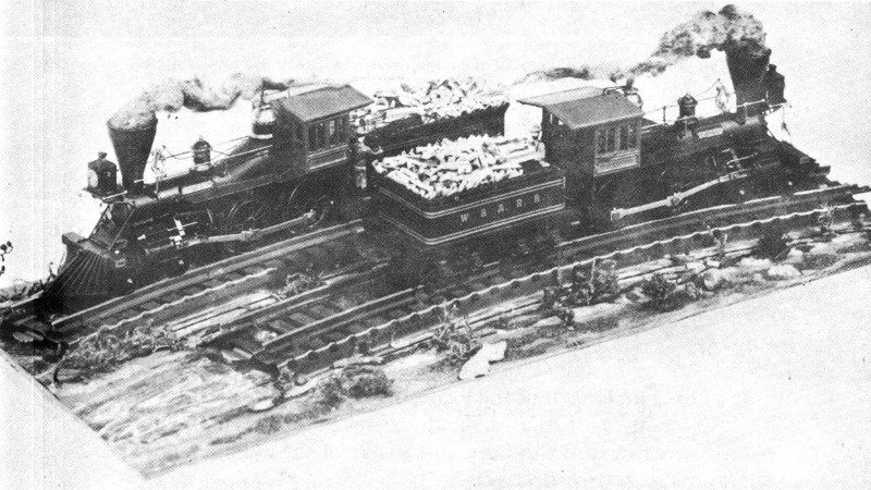
Figure 67.—Model of Rogers, Ketchum & Grosvenor General, 1855.
American-Type Locomotive of about 1890
An operable model (figure 68) in the Museum’s collection (USNM 309515), appears to represent a New York Central and Hudson River Railroad 4-4-0 locomotive of the 86 period of about 1890. This class of locomotive was built by the Schenectady Locomotive Works to the New York Central’s design, and had 78-inch driving wheels, cylinders with a bore of 19 inches and a stroke of 24 inches, and weighed 120,000 pounds.
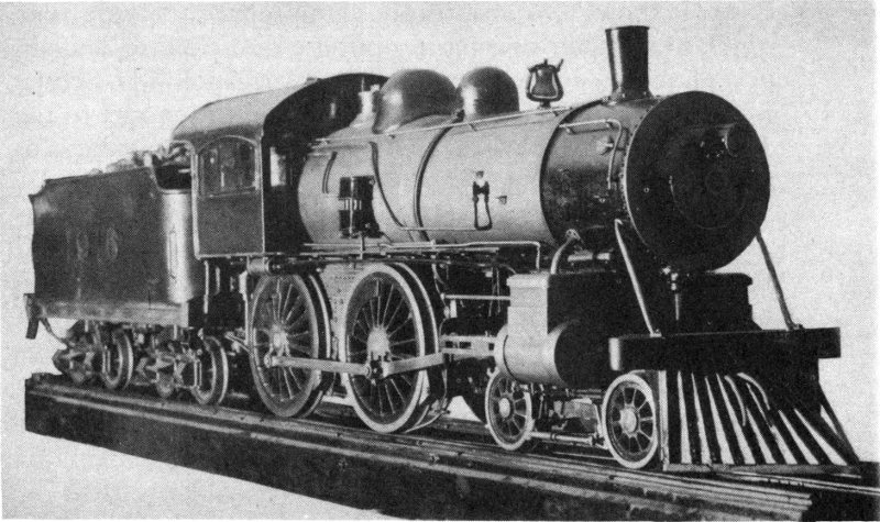
Figure 68.—Operable model of an American-type locomotive of about 1890.
Work on this model was commenced by the donor, the late Robert E. M. Bain, in 1916, and it was completed about three years later, only spare time having been employed in its construction. The model was given to the Museum in 1928. The length of the locomotive and tender is 80 inches, the gauge is 6½ inches, the diameter of the driving wheels is 8⁹/₁₆ inches, and the bore and stroke of the cylinders are 1½ and 3 inches, respectively.
The brakes on the model are inoperative, as the actuating cylinders for the brake system are dummies. On the other hand, such parts as the boiler, firebox, steam gauge, water gauge, throttle, and valve motion are all operable, and the donor has asserted that there is even ring packing in the cylinders. Although capable of being fired and steamed up, using coal as the fuel, the locomotive has never been operated.
87
The number on the locomotive and tender apparently represent the year the donor commenced his work on the model, as there was never a New York Central locomotive of this type bearing that number.
New York Central Locomotive 999, 1893
The Museum’s nonoperable model (figure 69) of the famous 999, long the holder of the world’s speed record, was built especially for the Museum’s collection (USNM 313161), and was the gift in 1947 of the New York Central System. Constructed by Edwin P. Alexander of Yardley, Pa., it is about 15 inches long with tender and is accompanied by a train of four model cars of the period. Locomotive and cars are built to a scale of ¼ inch to the foot.
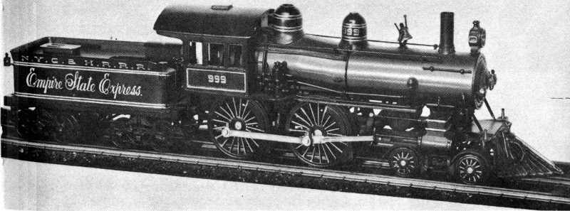
Figure 69.—Model of New York Central American-type locomotive 999, 1893.
One of the best known of all locomotives, the New York Central and Hudson River Railroad’s 999, with engineer Charles H. Hogan at the throttle, reached a speed of 112½ miles an hour over a measured mile on May 10, 1893, while pulling the Empire State Express westward between Batavia and Buffalo, N. Y. This was a new world’s record, and the 999 was shortly withdrawn from active service and placed on exhibition at the World’s Columbian Exposition at Chicago.
88
At the conclusion of the exposition it was again placed in service with the Empire State Express, but was later withdrawn because, although having great speed with a light train, it lacked the pulling power required for the larger and heavier trains then coming into use. Today, the 999, altered somewhat, and with smaller driving wheels than when built, is preserved by the New York Central System as one of its historic relics. It is usually to be seen at the Collinwood shops near Cleveland, Ohio, but it still occasionally appears at fairs and expositions.
Designed by the superintendent of motive power, William Buchanan, and constructed at the West Albany shops of the New York Central, the 999 is of the 4-4-0, or American, type and was fitted originally with 86-inch driving wheels. The bore and stroke of the cylinders are 19 and 24 inches, respectively, and a steam pressure of 180 pounds per square inch was used. The fuel was bituminous coal. The extreme wheelbase is 287 inches, and the distance between the two driving axles is 102 inches. The weight of the locomotive is 124,000 pounds, that of the loaded tender is 80,000.
American-Type Locomotive of about 1900
Through the bequest in 1955 of John Semple Clarke, a model (figure 70) formerly lent by him to the Museum has been added to the collection (USNM 314615). A 4-4-0 of exquisite workmanship in brass and steel, the model is 21 inches long and has a gauge of 2½ inches.
It was constructed during the 7-year period from 1907 to 1914 by George Boshart, a toolmaker of Brookline, near Philadelphia, Pa. All rotating and reciprocating parts are operable, though the boiler is apparently not capable of generating steam. There is no tender with the locomotive, none having been built.
It is not definitely known what, if any, original locomotive the model represents, but some of its details are similar to those of locomotives built at the turn of the century by the Schenectady Locomotive Works. While it has been stated that Boshart patterned the model after a Pennsylvania 89 Railroad locomotive with which he was familiar, in certain of its details the model does not appear to justify this claim. The number on the model represents the year in which its construction was started.
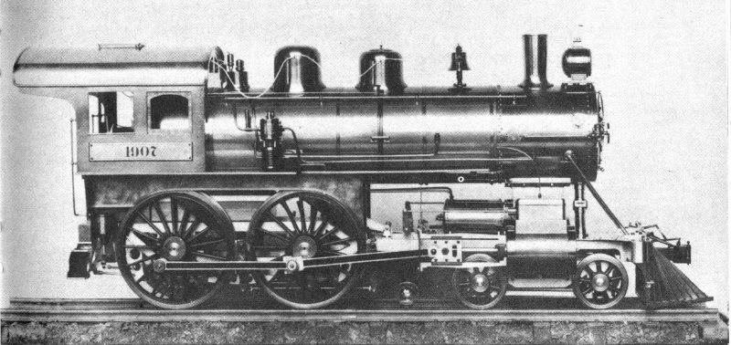
Figure 70.—Model of an American-type locomotive of about 1900.
British Locomotive of about 1905
In the national collection is an operable model (figure 71) of a British locomotive of the period of about 1905. Made by the well known English model makers Carson and Co., and given in 1933 to the Museum by Frank A. Wardlaw and Frank A. Wardlaw, Jr., the model (USNM 310584) represents the Caledonian Railway Co. No. 903, a 4-6-0 with inside cylinders. The length of the locomotive and the 6-wheeled tender is 45 inches and the gauge is 3¼ inches. A locomotive of similar appearance, though not necessarily identical, is described and illustrated in the British technical journal “Engineering” for August 31, 1906 (p. 299).
The elder Wardlaw stated that the model was built by Carson for Sir Henry Lopes, and that he acquired it from Carson when Sir Henry turned it in on a new one. Wardlaw 90 believed this gasoline-fueled model to have been the first model locomotive ever built with a flash boiler.
A letter from James C. Crebbin in the July 27, 1933, issue of the British journal “The Model Engineer and Practical Electrician,” contains the following statement:
When I was chairman of Messrs. Carson and Co., the late Mr. James Carson and I collaborated in the development of flash steam model locomotives.
With the exception of the very small model L. & N. W. “Experiment” loco which had only one coil, and a methylated vaporising burner, the boilers had longitudinal coils running the full length of the boiler, and were fired by means of a Carson Primus type burner. The pressure container was a drum inside the tender, and was surrounded by water in the usual square or oblong tank. This water fed the geared pump, which was driven from the second tender axle.
The most successful of this type was a ¾-inch-scale 4-4-0 Caledonian, built for Sir Henry Lopes. Mr. Carson always declared that this engine was the fastest he had ever seen, and during tests he carried out, on Sir Henry’s track, never dared to give the model more than half-throttle, no matter what load the engine was hauling.
Mr. Wardlaw, of New York, and a “M. E.” Exhibition Championship Cup Holder, has a similar locomotive which, I believe, is destined for exhibition in some museum in U. S. A.
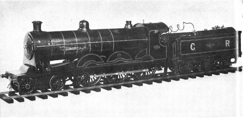
Figure 71.—Operable model of a British locomotive of about 1905.
91
British Locomotive, 1905
An operable model (figure 72) of locomotive No. 146 of the Ferrocarril Oeste of Argentina was presented to the Museum (USNM 310585) in 1933 by Frank A. Wardlaw and Frank A. Wardlaw, Jr. The 22-inch-long model has a gauge of 2½ inches. Gasoline carried in the tender is used as fuel. The builder is not known.
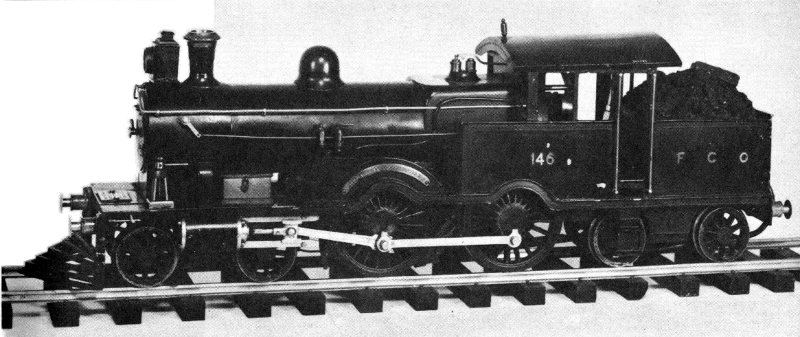
Figure 72.—Operable model of a British locomotive, 1905.
The original locomotive No. 146, a 4-4-4-T type with a cowcatcher and outside cylinders, was built in 1905 by Beyer, Peacock & Co., Ltd., of Manchester, England. The locomotive and tender have a common frame. According to a small plate affixed to the model, the original was the first locomotive to be fitted with “Wardlaw’s composite clackvalve.” This invention of the elder Wardlaw was installed at Buenos Aires in January 1908, according to the legend on the plate.
92
The original Greyhound was locomotive No. 302 of the London and North-Western Railway Co., built in 1905 at the Crewe works of the company. Of the 4-4-0 type, the locomotive had inside cylinders and was the first in Europe to be fitted with “Wardlaw’s composite clackvalve.” This was done in August 1910.
The model of the locomotive and its 6-wheeled tender (figure 73) is 29 inches long and has a gauge of 2½ inches. It is operable, using gasoline carried in the tender as fuel. The builder is not known.
The donors, Frank A. Wardlaw and Frank A. Wardlaw, Jr., presented the model (USNM 310586) to the Museum in 1933.
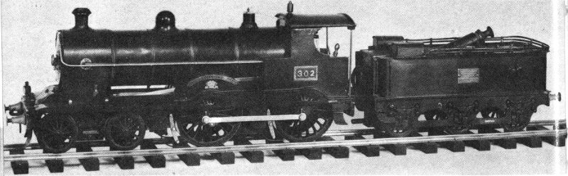
Figure 73.—Operable model of British locomotive Greyhound, 1905.
Pennsylvania Atlantic-Type Locomotive, 1907
The Atlantic-type steam locomotive is represented in the Museum collection by a nonoperable model (figure 74) lent to the Museum in 1922 by E. Howard Askew of Baltimore, Md. Constructed by the lender, the model (USNM 307949) is 32 inches long and has a gauge of 2½ inches.
It represents the Pennsylvania Railroad class E3sd No. 5127, a 4-4-2 steam locomotive with Walschaert valve gear. 93 The original locomotive was built at the railroad’s Juniata shops, Altoona, Pa., in August 1907, construction No. 1734. Originally a class E3d locomotive, it was converted to an E3sd in June 1913 by the addition of a superheater in the Wilmington, Del., shops of the road.
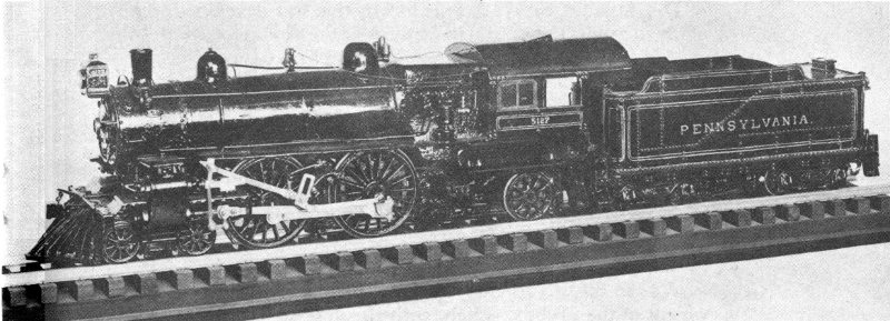
Figure 74.—Model of Pennsylvania Atlantic-type locomotive, 1907.
In a letter to Askew (Dec. 14, 1922) the chief of motive power of the Pennsylvania System, J. T. Wallis, stated that the cylinders of the original had a bore and stroke of 22 and 26 inches. The drivers were 80 inches in diameter and the boiler carried a steam pressure of 205 pounds. The boiler had a minimum (internal) diameter of 65½ inches, and it contained 170 2-inch flues and 24 5½-inch flues, while the superheater consisted of 96 1½-inch flues. The distance between flue sheets was 180 inches and the total heating surface was 2,571 square feet. The grate was 111 inches long and 72 wide.
The total weight on the drivers was 127,200 pounds, on the engine truck 35,500 pounds, and on the trailer truck 33,900 pounds—or a total of 196,600 pounds in working order. The weight of the tender in working order was 134,000 pounds. The tractive force of the locomotive was 27,409 pounds.
In his letter Wallis also made the following statement to explain the significance of the modification of this class of locomotive:
94
The Atlantic, or 4-4-2, type locomotive was developed in an effort to retain the desirable features of the American, or 4-4-0, type of locomotive and at the same time to produce a locomotive in answer to the demand for greater power. To do this, the firebox was increased in area by making it considerably wider, so that a greater amount of soft coal could be burned. The diameter of the barrel of the boiler was increased to allow for greater heating surface, which, of course, increased the weight on the drivers.
To make room for the driving wheels without unduly increasing the length of the tubes in the boiler, the driving wheels were moved forward, the main driver being in the rear instead of in front as in the American type locomotive. In order to carry the weight of the firebox, which, with the new driving wheel location, overhangs the rear driver too much to be properly supported, a two-wheel trailer truck was used. This trailer truck, which is fulcrumed a short distance back of the main driver, is so designed that it has lateral motion, and provision is made for ash pan as well as firebox clearance.
By the use of higher steam pressure, larger heating surface and grate area, the use of passenger locomotives of the three-coupled type, with the troubles incident to the use of long parallel rods, was put off for a decade.
General Electric Locomotive, 1926
A detailed and exquisitely made operable model of the New York Central class T-3A electric locomotive No. 1173, now No. 273, was constructed by W. Howard R. Parsons, and was donated by him in 1952 to the Museum (USNM 314237).
The model (figure 75) is powered by eight electric motors, as is the full sized original, one for each axle, but because of space limitations and power requirements the model’s drive is through gears rather than direct. The model operates on 12-volt direct current. Its length is 43 inches and its gauge is 3½ inches.
The New York Central System purchased 10 class T-3A locomotives in late 1926 at a cost of $100,000 each. These supplemented an earlier group of 10 T-1’s and 16 T-2’s built for the New York Central from 1913 to 1917 at the Erie, Pa., plant of the General Electric Co. Of this total of 95 36 locomotives only one, No. 270 (formerly No. 1170), had been stricken from the records as of December 1954. The remaining 35 still perform routine passenger service between New York and Harmon, and New York and North White Plains. The numbers in the group now run from 247 to 282 (formerly 1147 to 1182), with the exception of the scrapped No. 270.
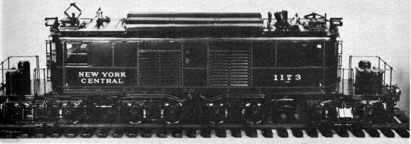
Figure 75.—Operable model of General Electric locomotive, 1926.
With an operating weight of 292,600 pounds, the locomotives of the T-3A class develop 1,908 horsepower continuously, with a tractive force of 12,750 pounds, and they can develop 2,488 horsepower for 1 hour, with a tractive force of 18,440 pounds. The maximum speed of a T-3A is 75 miles an hour. These locomotives operate on 660-volt direct current, usually obtained from a third rail. The pantographs are used only when crossing certain complicated crossover switches. Each of the eight axles is driven by its individual gearless motor. The overall wheelbase is 46 feet, 5 inches, the overall length 56 feet, 10 inches.
B & O Hudson-Type Locomotive Lord Baltimore, 1935
During the winter of 1936-1937, The Baltimore and Ohio Railroad Co. conducted in conjunction with the magazine “The Model Craftsman” a contest among model builders for the construction of a model of the railroad’s Washington-to-Jersey 96 City lightweight, streamlined train, the “Royal Blue,” first placed in operation on June 24, 1935.
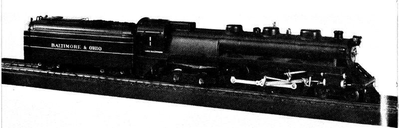
Figure 76.—Model of B & O Hudson-type locomotive Lord Baltimore, 1935.
The contest, with a first prize of $500, was won by Fletcher G. Speed of New Rochelle, N. Y., and his prize-winning train (figure 76) was presented by the Baltimore and Ohio in 1937 to the National Museum (USNM 311191). The train consists of the Hudson-type, or 4-6-4, steam locomotive Lord Baltimore and tender, together 2 feet long, plus five cars. Beautiful in workmanship, and powered with a small electric motor, the model is built to a scale of ¼ inch to the foot.
The original locomotive Lord Baltimore was designed by the Baltimore and Ohio, and was constructed at the company’s Mount Clare shops in Baltimore. The weight of the locomotive and tender in working order was 527,000 pounds, and the tractive force was 38,000 pounds. The driving wheels were 84 inches in diameter, and the driving wheelbase was 178 inches. The bore and stroke of the cylinders were 20 and 28 inches, respectively, Walschaert valve gear was used, and a steam pressure of 350 pounds per square inch was employed. The fuel was bituminous coal.
On September 11, 1935, an average speed of 59.28 miles an hour was obtained between Washington and Jersey City while pulling a dynamometer car and five other cars. Although designated as No. 2 when built in 1935, the locomotive was changed to No. 5340 in 1942. As it was not designed to handle standard weight trains, the locomotive was later removed from service, and after being in storage for several years was scrapped on July 19, 1949.
97
Lima Northern-Type Locomotive, 1937
A black, red, and orange nonoperable model (figure 77) in the collection represents the Southern Pacific Co. No. 4410, the first of the many such streamlined 4-8-4, or Northern-type, steam locomotives built for that line. This model of No. 4410 and its tender, about 27 inches long, is built to the scale of ¼ inch to the foot. The gift of the Southern Pacific Co. in 1937, it was made early in that year especially for the Museum’s collection (USNM 311340).
The first group of this type of streamliner, which was the conception of George McCormick and Frank E. Russell of the Southern Pacific, was completed by the Lima Locomotive Works in January 1937. The first run with one of these streamliners was made on March 21 with the “Coast Daylight” passenger train between San Francisco and Los Angeles.
Of the total of 50 essentially similar locomotives of this streamlined class, the Southern Pacific still had 49 in November 1954, only No. 4414 having been authorized for scrapping. At that time, these locomotives had averaged approximately 13,000 miles a month since being placed in service, although many had completed over 15,000 miles in particularly productive months. The earlier ones, represented by this model, developed 4,500 horsepower at 55 miles an hour and had a top speed of 90 miles an hour, although 75 was the highest allowable operating speed. They were able to maintain a 9¾-hour schedule between San Francisco and Los Angeles.
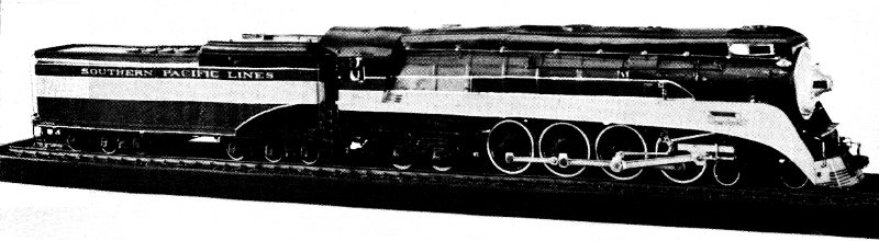
Figure 77.—Model of Lima Northern-type locomotive, 1937.
98
The locomotive and tender are 108 feet long, and weigh 835,000 pounds in operating condition. The fuel is bunker type C oil. A boiler pressure of 250 pounds per square inch is employed. The cylinder bore is 27 inches, the stroke 30. The eight drivers are 73 inches in diameter, and the driving wheelbase is 20 feet. The later streamlined 4-8-4’s of the Southern Pacific develop 5,500 horsepower at 55 miles an hour, and operate on a boiler pressure of 300 pounds per square inch.
General Electric Locomotive, 1938
A nonoperable model (figure 78) of the first of six 2-C+C-2 streamlined electric locomotives built by the General Electric Co. for The New York, New Haven and Hartford Railroad Co. was made especially for the Museum collection (USNM 311880) by the builder of these locomotives. The model, constructed in the Bridgeport, Conn., plant of the General Electric Co. and presented to the Museum in 1940, is of plaster painted green and black, with gold trim. It is 31 inches long and has a gauge of 1¾ inches.
The electric locomotives represented by this model were built in 1938 at the Erie, Pa., plant of the General Electric Co. for passenger service between New Haven and New York. Originally numbered from 0361 to 0366, they are now numbered from 360 to 365.
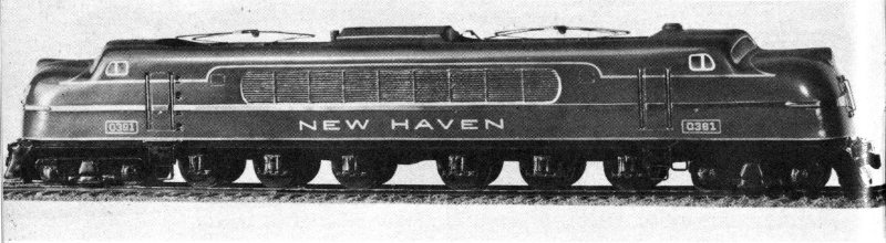
Figure 78.—Model of General Electric locomotive, 1938.
99
On the New Haven tracks these 77-foot-long locomotives operate on 11,000-volt, single-phase, 25-cycle, alternating current obtained from an overhead trolley system. On the New York Central tracks they operate on 660-volt direct current obtained usually from a third rail, but occasionally from an overhead supply at some crossover switches. For this latter purpose a small auxiliary pantograph is used. Control equipment is, of course, provided for both types of power supply.
The fully loaded weight is 433,200 pounds, of which 272,400 pounds is on the twelve 56-inch drivers. While operating on alternating current, the continuous tractive force is 24,100 pounds, and the continuously available horsepower 3,600. The maximum available horsepower from the six twin-armature, 12-pole motors is 7,600. Slightly different results are obtained while operating on direct current. The maximum safe speed is 93 miles an hour.
American Locomotive Co. Hudson-Type Locomotive, 1938
Development of the original Hudson-type locomotives began in 1926 when the New York Central System decided it needed a new type of passenger locomotive to meet the demands of high-speed, long-distance runs. The type was named after the river along which it would run. In late 1937 and in 1938, 50 Hudsons of an improved design, built by the American Locomotive Co., were placed on the New York Central. These locomotives, Nos. 5405 to 5454, had larger boilers than their predecessors, had greater tractive force, and were fitted with roller bearings. In addition, Nos. 5445 to 5454 were streamlined.
A nonoperable model (figure 79) in the Museum collection (USNM 313162), gift of the New York Central System in 1947, represents No. 5429. The model locomotive and tender are 2 feet long and are accompanied by a train of six streamlined cars. The entire train is painted silver, with black trimming on the locomotive and tender. Built to a scale of ¼ inch to the foot, it was especially made for the 100 Museum, the builder being Edwin P. Alexander of Yardley, Pa.
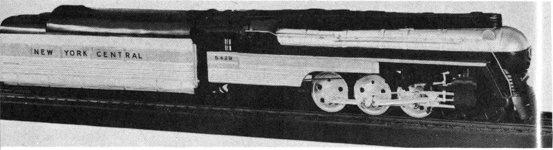
Figure 79.—Model of American Locomotive Co. Hudson-type locomotive, 1938.
The original No. 5429, constructed in 1938, was streamlined in 1941 in the West Albany shops of the New York Central, and in December of that year was placed back in service on the Empire State Express with an entirely new streamlined train of specially designed stainless-steel cars. When the Empire State Express was ultimately dieselized in 1945, No. 5429 was put to other uses, and the streamlining was removed in 1950. As of October 1955 it was still in service.
In streamlined condition, as represented by the model, the locomotive and tender together weighed 681,900 pounds and their length was a few inches over 97 feet. The diameter of the driving wheels was 79 inches, the bore and stroke of the cylinders were 22½ and 29 inches, respectively, and the total tractive force was 53,960 pounds. A steam pressure of 265 pounds per square inch was used.
Baldwin-Westinghouse Geared Steam-Turbine Locomotive, 1944
A radical departure from the usual design for a coal-burning steam locomotive, and the first of its type built in this country, was the noncondensing geared steam-turbine locomotive built jointly by The Baldwin Locomotive Works and the Westinghouse Electric and Manufacturing Co. Constructed in 1944 at Baldwin’s Eddystone plant (Westinghouse 101 manufactured the turbines and gears), it was designated Pennsylvania Railroad Co. class S-2 locomotive No. 6200.
This locomotive, combining the work of two pioneers in the railroad equipment field, is represented in the Museum collection by a nonoperable model (figure 80) made especially for the Museum (USNM 312935) and presented to it by The Baldwin Locomotive Works early in 1946. The locomotive and tender, together 30 inches long, were built to a scale of ¼ inch to the foot by Minton Cronkhite of Pasadena, Calif.
Two steam turbines, similar to the type that drive the larger fighting ships of the U.S. Navy, powered the original locomotive. The more complex and powerful of the two, the forward-drive turbine, developed a maximum of 7,250 horsepower and was at all times engaged with the wheels. (Although 6,500 horsepower has usually been the quoted figure for the forward-drive turbine, 7,250 was actually developed on October 22, 1946, at the Altoona Locomotive Testing Plant.) The simpler one, for reverse only, developed 1,500 horsepower and was normally disengaged from the driving wheels except while actually being used.
The boiler, frame, trucks, and driving wheels were of the conventional type, the most notable visible difference between the locomotive and those of other types being the absence of cylinders, valve motion, and their accompanying parts. Because of the elimination of piston rods and other reciprocating parts it was possible to balance almost perfectly the driving wheels, thus permitting a higher operating speed than normally practical with a conventional locomotive.
The weight of the locomotive alone was 580,000 pounds, and its forward tractive force was 70,500 pounds. A 6-8-6 wheel arrangement was employed, the driving wheel diameter was 68 inches, and a speed of 100 miles an hour was possible. The working steam pressure was 310 pounds per square inch. Bituminous coal served as the fuel. A detailed and well illustrated description of this locomotive appears in the magazine “Baldwin” (for the fourth quarter of 1944).
The locomotive covered 103,050 miles in passenger service, 102 and was then set aside on June 11, 1949, because it was in need of repairs to the firebox and flues, and also to the turbines, oil pumps, and gears. At that time all passenger service on the Pennsylvania was being changed to diesel-electric operation, so the locomotive was ultimately scrapped on May 29, 1952.
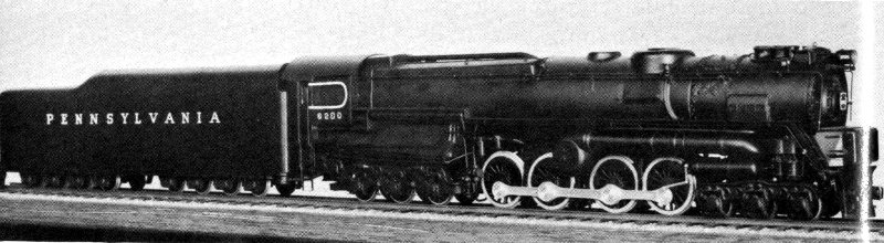
Figure 80.—Model of Baldwin-Westinghouse geared steam-turbine locomotive, 1944.
General Motors Diesel-Electric Locomotive, 1945
A nonoperable model of a diesel-electric locomotive (figure 81) was given to the Museum (USNM 313163) by the New York Central System in 1947. This gray and black model, which is 33 inches long and is built to a scale of ¼ inch to the foot, represents the General Motors 2-unit diesel-electric No. 4000-4001 of the New York Central, a type placed in service with the Empire State Express in 1945 to replace the Hudson-type steam locomotives described on page 99. The model was especially built for the Museum’s collection, the builder being Edwin P. Alexander of Yardley, Pa.
The overall length of the two full sized units is just over 140 feet and their combined weight is 646,000 pounds. Each end of each unit is supported by a 6-wheeled truck, and the wheel diameter is 36 inches throughout.
Each unit is equipped with two General Motors 12-cylinder V-type 2-cycle diesel engines having a bore of 8½ inches and a stroke of 10 inches, and developing 1,000 horsepower 103 at 800 revolutions per minute, a total of 4,000 horsepower for the two units combined. Each engine is directly coupled to a generator that supplies direct current to the two traction motors, geared, respectively, to the front and rear axles of its corresponding truck. No power is applied to the center axle, which is for weight distribution only. The joint tractive force of the two units is 108,950 pounds.
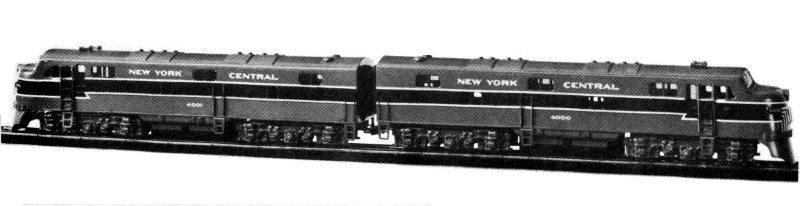
Figure 81.—Model of General Motors diesel-electric locomotive, 1945.
104