Chapter III
Reading edition
STEAM ENGINE DETAILS
Some of the most important details of a steam engine are those of its valve gear. The simplest form of valve is that known as the plain slide valve, and as nearly all others are a modification of this, it is essential that the designer should first familiarize himself with this particular type of valve in all its details of operation. After this has been done, a study of other forms of valves will be found a comparatively easy matter. The so called Corliss valve differs radically from the slide valve, but the results to be obtained and the terms used in its design are practically the same. The valve gear of a steam engine is made up of the valve or valves which admit steam to and exhaust it from the cylinder, and of the mechanism which governs the valve movements, the latter usually consisting of one or more eccentrics attached to the main shaft.
The Slide Valve
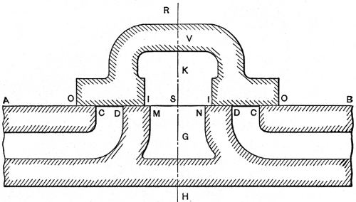
Fig. 8. Longitudinal Section of Slide Valve with Ports
Fig. 8 shows a longitudinal section of a slide valve with the ports, bridges, etc. The valve is shown in mid-position in order that certain points relating to it may be more easily understood. The valve, V, consists of a hollow casting, with ends projecting beyond the ports as shown; the lower face is smoothly finished and fitted to the valve seat AB. In operation it slides back and forth, opening and closing the ports which connect the steam chest with the cylinder. Steam is admitted to the cylinder when either port CD or DC is opened, and is released when the ports are brought into communication with the exhaust port MN. This is accomplished by the movement of the valve, which brings one of the cylinder ports and the exhaust port both under the hollow arch K. The portions DM and ND of the valve seat are called the bridges.
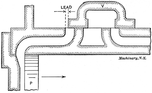
Fig. 9. Illustration showing Lead of Slide Valve
It will be seen by reference to Fig. 8 that the portions OI and IO are wider than the ports which they cover. This extra width is called the lap, OC being the outside lap and DI the inside or exhaust lap. The object of outside lap is that the steam may be shut off after the piston has moved forward a certain distance, and be expanded during the remainder of the stroke. If there were no outside lap, steam would be admitted throughout the entire stroke and there would be no expansion. If there were no inside lap, exhaust would take place throughout the whole stroke, and the advantages of premature release and compression would be lost. Hence, outside lap affects the cut-off, and inside lap affects release and compression. A valve has lead when it begins to uncover the steam port before the end of the return stroke of the piston. This is shown in Fig. 9, where the piston P is just ready to start on its forward stroke as indicated by the arrow. The valve has already opened a distance equal to the lead, and the steam has had an opportunity to enter and fill the clearance space before the beginning of the stroke. The lead varies in different engines, being greater in high-speed than in low-speed types.
The Eccentric
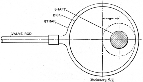
Fig. 10. Diagrammatical View of Eccentric
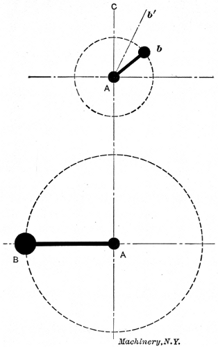
Fig. 11. Relations of Crank and Eccentric
The slide valve is usually driven by an eccentric attached to the main shaft. A diagram of an eccentric is shown in Fig. 10. An eccentric is, in reality, a short crank with a crank-pin of such size that it surrounds the shaft. The arm of a crank is the distance between the center of the shaft, and the center of the crank-pin. The throw of an eccentric corresponds to this, and is the distance between the center of the shaft and the center of the eccentric disk, as shown at a in Fig. 10. The disk is keyed to the shaft, and as the shaft revolves, the center of the disk rotates about it as shown by the dotted line, and gives a forward and backward movement to the valve rod equal to twice the throw a.
In Fig. 11 let A represent the center of the main shaft, B the crank-pin to which the connecting-rod is attached (see H, 1), and the dotted circle through B the path of the crank-pin around the shaft. For simplicity, let the eccentric be represented in a similar manner by the crank Ab, and its path by the dotted circle through b. Fig. 12 shows a similar diagram with the piston P and the valve in the positions corresponding to the positions of the crank and eccentric in Fig. 11, and in the diagram at the right in Fig. 12. The piston is at the extreme left, ready to start on its forward stroke toward the right. The crank-pin B is at its extreme inner position. When the valve is at its mid-position, as in Fig. 8, the eccentric arm Ab will coincide with the line AC, Fig. 11. If the eccentric is turned on the shaft sufficiently to bring the left-hand edge O, Fig. 8, of the valve in line with the edge C of the port, the arm of the eccentric will have moved from its vertical position to that shown by the line Ab´ in Fig. 11. The angle through which the eccentric has been turned from the vertical to bring about this result is called the angular advance, and is shown by angle CAb´ in Fig. 11. The angular advance evidently depends upon the amount of lap.
If the valve is to be given a lead, as indicated in Fig. 12, the eccentric must be turned still further on the shaft to open the valve slightly before the piston starts on its forward movement. This brings the eccentric to the position Ab shown in Fig. 11. The angle through which the eccentric is turned to give the necessary lead opening to the valve is called the angle of lead, and is shown by angle b´Ab. By reference to Fig. 11, it is seen that the total angle between the crank and the eccentric is 90 degrees, plus the angular advance, plus the angle of lead. This is the total angle of advance.
The relative positions of the piston and valve at different periods of the stroke are illustrated in Figs. 12 to 16. Fig. 12 shows the piston just beginning the forward stroke, the valve having uncovered the admission port an amount equal to the lead. The crank is in a horizontal position, and the eccentric has moved from the vertical an amount sufficient to move the valve toward the right a distance equal to the outside lap plus the lead. The arrows show that steam is entering the left-hand port and is being exhausted through the right-hand port.
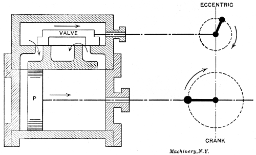
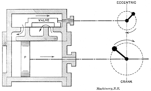
Fig. 12. Piston just beginning Forward Stroke Fig. 13. Steam Port fully Opened
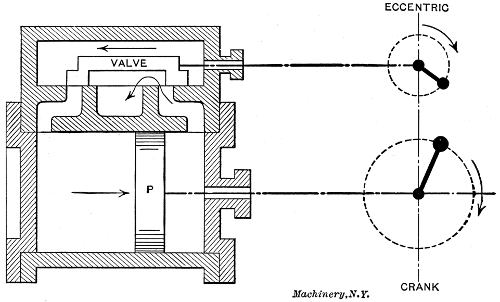
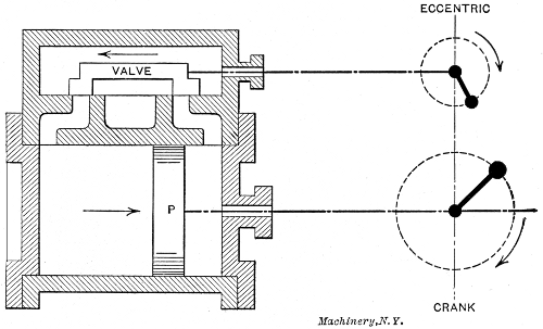
Fig. 14. Valve has started on Backward Stroke Fig. 15. Both Steam Ports Closed
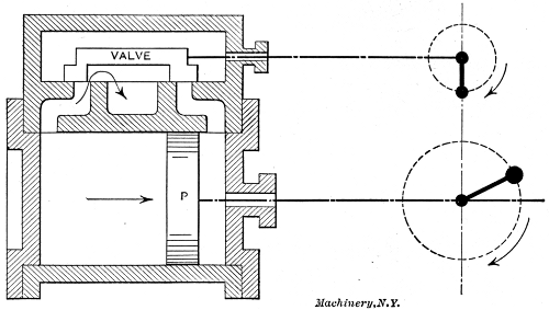
Fig. 16. Exhaust Begins
In Fig. 13 it is seen that the valve has traveled forward sufficiently to open the steam port to its fullest extent, and the piston has moved to the point indicated. The exhaust port is still wide open, and the relative positions of the crank and eccentric are shown in the diagram at the right. In Fig. 14 the eccentric has passed the horizontal position and the valve has started on its backward stroke, while the piston is still moving forward. The admission port is closed, cut-off having taken place, and the steam is expanding. The exhaust port is still partially open.
In Fig. 15 both ports are closed and compression is taking place in front of the piston while expansion continues back of it. Release occurs in Fig. 16 just before the piston reaches the end of its stroke. The eccentric crank is now in a vertical position, pointing downward, and exhaust is just beginning to take place through the left-hand port. This completes the different stages of a single stroke, the same features being repeated upon the return of the piston to its original position. The conditions of lap, lead, angular advance, etc., pertain to practically all valves, whatever their design.
Different Types of Valves
In the following are shown some of the valves in common use, being, with the exception of the Corliss, modifications of the plain slide valve, and similar in their action.
Double-Ported Balanced Valve.—A valve of this type has already been shown in Fig. 2. This valve is flat in form, with two finished surfaces, and works between the valve-seat and a plate, the latter being prevented from pressing against the valve by special bearing surfaces which hold it about 0.002 inch away. The construction of the valve is such that when open the steam reaches the port through two openings as indicated by the arrows at the left. The object of this is to reduce the motion of the valve and quicken its action in admitting and cutting off steam.
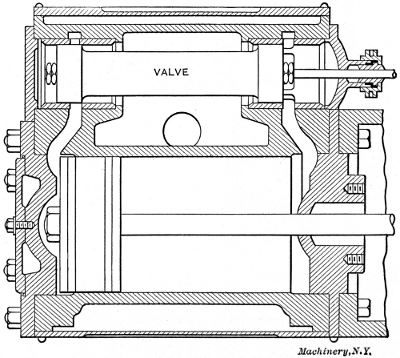
Fig. 17. Engine with Piston Valve
Piston Valve.—The piston valve shown in Fig. 17 is identical in its action with the plain slide valve shown in Fig. 8, except that it is circular in section instead of being flat or rectangular. The advantage claimed for this type of valve is the greater ease in fitting cylindrical surfaces as compared with flat ones. The valve slides in special bushings which may be renewed when worn. Piston valves are also made with double ports.
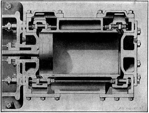
Fig. 18. Section through Cylinder of Engine of the Four-valve Type
Four-Valve Type.—Fig. 18 shows a horizontal section through the cylinder and valves of an engine of the four-valve type. The admission valves are shown at the top of the illustration and the exhaust valves at the bottom, although, in reality, they are at the sides of the cylinder. The advantage of an arrangement of this kind is that the valves may be set independently of each other and the work done by the two ends of the cylinder equalized. The various events, such as cut-off, compression, etc., may be adjusted without regard to each other, and in such a manner as to give the best results, a condition which is not possible with a single valve.
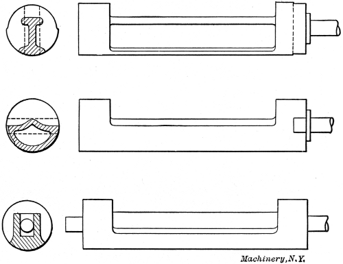
Fig. 19. Different Types of Corliss Valves
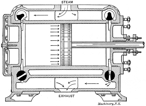
Fig. 20. Longitudinal Section through Corliss Engine
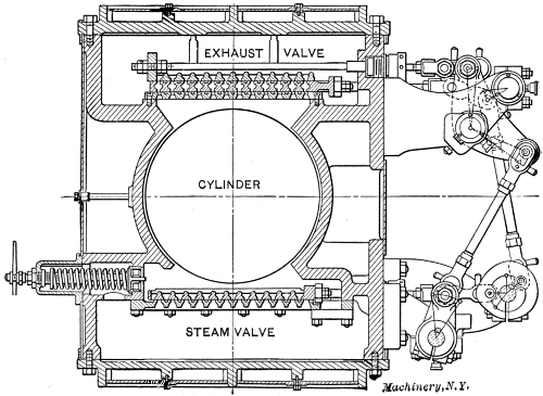
Fig. 21. The Gridiron Valve
Gridiron Valve.—One of the principal objects sought in the design of a valve is quick action at the points of admission and cut-off. This requires the uncovering of a large port opening with a comparatively small travel of the valve. The gridiron valve shown in Fig. 21 is constructed especially for this purpose. This valve is of the four-valve type, one steam valve and one exhaust valve being shown in the section. Both the valve and its seat contain a number of narrow openings or ports, so that a short movement of the valve will open or close a comparatively large opening. For example, the steam valve in the illustration has 12 openings, so that if they are 1⁄4 inch in width each, a movement of 1⁄4 inch of the valve will open a space 12 × 1⁄4 = 3 inches in length.
Corliss Valve.—A section through an engine cylinder equipped with Corliss valves is shown in Fig. 20. There are four cylindrical valves in this type of engine, two steam valves at the top and two exhaust valves at the bottom. This arrangement is used to secure proper drainage. The action of the admission and exhaust valves is indicated by the arrows, the upper left-hand and the lower right-hand valve being open and the other two closed.
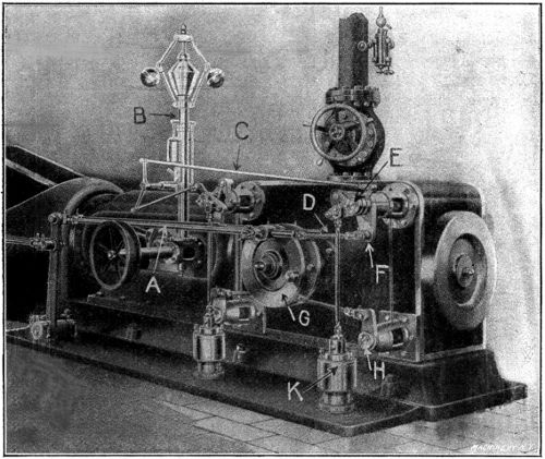
Fig. 22. The Monarch Engine with Corliss Valve Gear.—A, Rod to Eccentric; B, Governor; C, Reach Rod; D, Radial Arm; E, Steam Valve; F, Bell-crank; G, Wrist Plate; H, Exhaust Valve; K, Dash-pot
Side and sectional views of different forms of this type of valve are shown in Fig. 19. They are operated by means of short crank-arms which are attached to a wrist-plate by means of radial arms or rods, as shown in Fig. 22. The wrist-plate, in turn, is given a partial backward and forward rotation by means of an eccentric attached to the main shaft and connected to the upper part of the wrist-plate by a rod as indicated. The exhaust valves are both opened and closed by the action of the wrist-plate and connecting rods. The steam valves are opened in this manner, but are closed by the suction of dash pots attached to the drop levers on the valve stems by means of vertical rods, as shown.
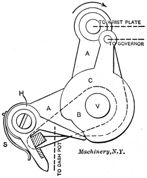
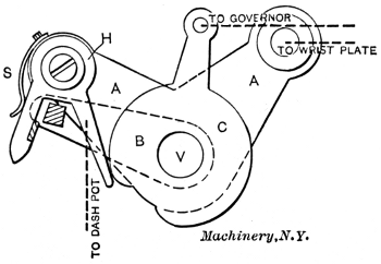
Fig. 23 Fig. 24
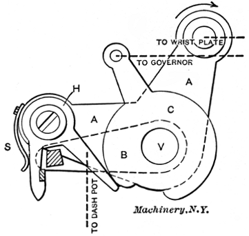
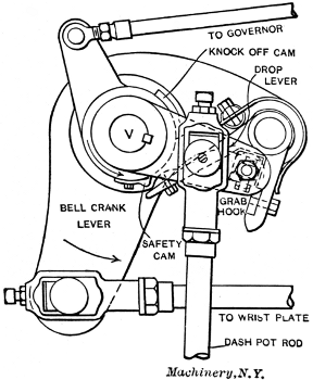
Fig. 25 Fig. 26
Figs. 23 to 26. Action of Corliss Valve Gear
The action of the steam or admission valves is best explained by reference to Figs. 23 to 26. Referring to Fig. 23, A is a bell-crank which turns loosely upon the valve stem V. The lower left-hand extension of A carries the grab hook H, while the upper extension is connected with the wrist-plate as indicated. Ordinarily the hook H is pressed inward by the spring S, so that the longer arm of the hook is always pressed against the knock-off cam C. The cam C also turns upon the valve stem V and is connected with the governor by means of a reach rod as indicated in Fig. 23 and shown in Fig. 22. The drop lever B is keyed to the valve stem V, and is connected with the dash pot by a rod as indicated by the dotted line. This is also shown in Fig. 22. The end of the drop lever carries a steel block (shown shaded in Fig. 23), which engages with the grab hook H.
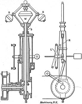
Fig. 27. Governor for Corliss Engine
When in operation, the bell-crank is rotated in the direction of the arrow by the action of the wrist-plate and connecting-rod. As the bell-crank rotates, the grab hook engages the steel block at the end of the drop lever B and lifts it, thus causing the valve to open, and to remain so until the bell-crank has advanced so far that the longer arm of the grab hook H is pressed outward by the projection on the knock-off cam, as shown in Fig. 24. The drop lever now being released, the valve is quickly closed by the suction of the dash pot, which pulls the lever down to its original position by means of the rod previously mentioned.
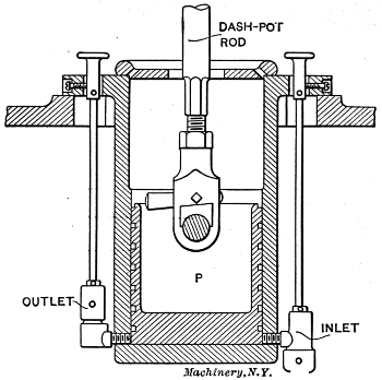
Fig. 28. Dash-pot for Corliss Engine
The governor operates by changing the point of cut-off through the action of the cam C. With the cam in the position shown in Fig. 25, cut-off occurs earlier than in Fig. 24. Should the cam be turned in the opposite direction (clockwise), cut-off would take place later. A detailed view of the complete valve mechanism described is shown assembled in Fig. 26, with each part properly named. A detail of the governor is shown in Fig. 27. An increase in speed causes the revolving balls BB to swing outward, thus raising the weight W and the sleeve S. This in turn operates the lever L through rod R and a bell-crank attachment, as shown in the right-hand view. An upward and downward movement of the balls, due to a change in speed of the engine, swings the lever L backward and forward as shown by the full and dotted lines. The ends of this lever are attached by means of reach-rods to the knock-off cams, this being shown more clearly in Fig. 22. The connections between the lever L and cam C are such that a raising of the balls, due to increased speed, will reduce the cut-off and thus slow down the engine. On the other hand, a falling of the balls will lengthen the cut-off through the same mechanism.
Mention has already been made of the dash pot which is used to close the valve suddenly after being released from the grab hook. The dash-pot rod is shown in Fig. 26, and indicated by dotted lines in Figs. 23 to 25. A detailed view of one form of dash pot is shown in Fig. 28. When the valve is opened, the rod attached to lever B, Figs. 23 and 24, raises the piston P, Fig. 28, and a partial vacuum is formed beneath it which draws the piston and connecting rod down by suction as soon as the lever B is released, and thus closes the valve suddenly and without shock. The strength of the suction and the air cushion for this piston are regulated by the inlet and outlet valves shown on the sides of the dash pot.
Engine Details
Figs. 29 to 37 show various engine details, and illustrate in a simple way some of the more important principles involved in steam engine design.
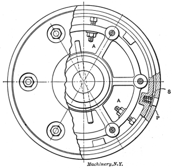
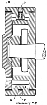
Figs. 29 and 30. Plan and Longitudinal Section of Adjustable Piston
A partial cross-section of an adjustable piston is shown in Fig. 29, and a longitudinal section of the same piston in Fig. 30. The principal feature to be emphasized is the method of automatic expansion employed to take up any wear and keep the piston tight. In setting up the piston a hand adjustment is made of the outer sleeve or ring R by means of the set-screws AA. Ring R is made in several sections, so that it may be expanded in the form of a true circle. Further tightness is secured without undue friction by means of the packing ring P which fits in a groove in R and is forced lightly against the walls of the cylinder by a number of coil springs, one of which is shown at S. As the cylinder and piston become worn, screws A are adjusted from time to time, and the fine adjustment for tightness is cared for by the packing ring P and the coil springs S.
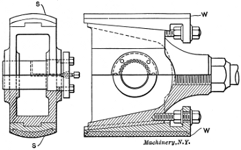
Fig. 31. A Typical Cross-head
The points to be brought out in connection with the cross-head are the methods of alignment and adjustment. A typical cross-head is shown in cross and longitudinal sections in Fig. 31. Alignment in a straight line, longitudinally, is secured by the cylindrical form of the bearing surfaces or shoes, shown at S. These are sometimes made V-shaped in order to secure the same result. The wear on a cross-head comes on the surfaces S, and is taken up by the use of screw wedges W, shown in the longitudinal section. As the sliding surfaces become worn, the wedges are forced in slightly by screwing in the set-screws and clamping them in place by means of the check-nuts.
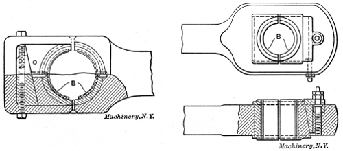
Figs. 32 and 33. Methods Commonly Used for Taking Up Wear in a Connecting-rod
The method commonly employed in taking up the wear in a connecting-rod is shown in Figs. 32 and 33. The wear at the wrist-pin is taken by the so called brasses, shown at B in the illustrations. The inner brass, in both cases, fits in a suitable groove, and is held stationary when once in place. The outer brass is adjustable, being forced toward the wrist-pin by a sliding wedge which is operated by one or more set-screws. In Fig. 32 the wedge is held in a vertical position, and is adjusted by two screws as shown. The arrangement made use of in Fig. 33 has the wedge passing through the rod in a horizontal position, and adjusted by means of a single screw, as shown in the lower view. With the arrangements shown, tightening up the brasses shortens the length of the rod. In practice the wedges at each end of the rod are so placed that tightening one shortens the rod, and tightening the other lengthens it, the total effect being to keep the connecting-rod at its original length.
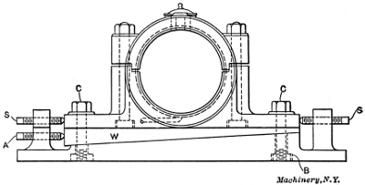
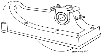
Fig. 34. Outboard Bearing for Corliss Type Engine Fig. 35. Inner Bearing and Bed of Corliss Engine
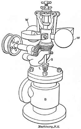
Fig. 36. Common Form of Throttling Governor
A common form of outboard bearing for an engine of the slow-speed or Corliss type is illustrated in Fig. 34. The various adjustments for alignment and for taking up wear are the important points considered in this case. The plate B is fastened to the stone foundation by anchor bolts not shown. Sidewise movement is secured by loosening the bolts C, which pass through slots in the bearing, and adjusting by means of the screws S. Vertical adjustment is obtained by use of the wedge W, which is forced in by the screw A, as required. The inner bearing and bed piece of a heavy duty Corliss engine is shown in Fig. 35. The bearing in this case is made up of four sections, so arranged that either horizontal or vertical adjustment may be secured by the use of adjusting screws and check-nuts.
Engines of the slide-valve type are usually provided either with a fly-ball throttling governor, or a shaft governor. A common form of throttling governor is shown in Fig. 36. As the speed increases the balls W are thrown outward by the action of the centrifugal force, and being attached to arms hinged above them, any outward movement causes them to rise. This operates the spindle S, which, in turn, partially closes the balanced valve in body B, thus cutting down the steam supply delivered to the engine. The action of a throttling governor upon the work diagram of an engine is shown in Fig. 38. Let the full line represent the form of the diagram with the engine working at full load. Now, if a part of the load be thrown off, the engine will speed up slightly, causing the governor to act as described, thus bringing the admission and expansion lines into the lower positions, as shown in dotted lines.
The shaft governor is used almost universally on high-speed engines, and is shown in one form in Fig. 37. It consists, in this case, of two weights W, hinged to the spokes of the wheel near the circumference by means of suitable arms. Attached to the arms, as shown, are coil springs C. The ends of the arms beyond the weights are connected by means of levers L to the eccentric disk. When the engine speeds up, the weights tend to swing outward toward the rim of the wheel, the amount of the movement being regulated by the tension of the springs C. As the arms move outward, the levers at the ends turn the eccentric disk on the shaft, the effect of which is to change the angle of advance and shorten the cut-off. When the speed falls below the normal, the weights move toward the center and the cut-off is lengthened. The effect of this form of governor on the diagram is shown in Fig. 39. The full line represents the diagram at full load, and the dotted line when the engine is under-loaded.
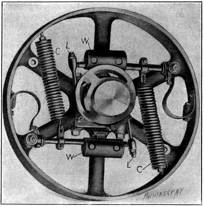
Fig. 37. Shaft Governor for High-speed Engine
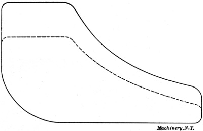
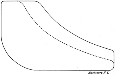
Fig. 38. Action of Throttling Governor on Indicator Diagram Fig. 39. Effect of Shaft Governor on Indicator Diagram
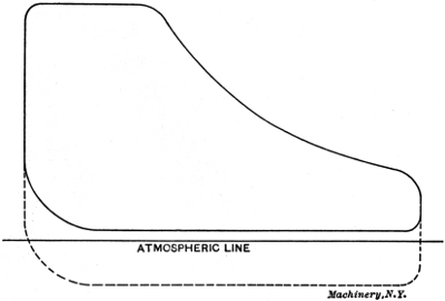
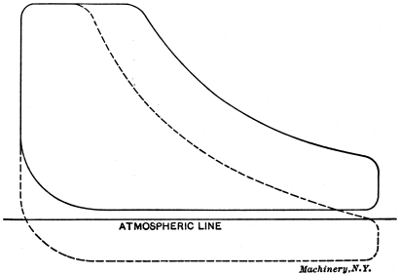
Fig. 40. Increasing Power of Engine by Condensing Fig. 41. Decreasing Steam Consumption by Condensing