DISCUSSION (continued 2)
Reading edition
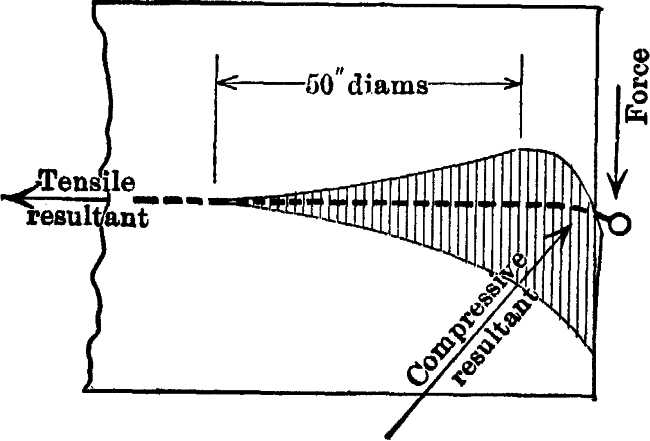
The distribution of the stress from the steel rod to the concrete can be represented by a cone, the base of which is at the outer face of the block, as the stresses will be zero at a point 50 diameters back, and will increase in a certain ratio out toward the face of the block, and will also, at all intermediate points, decrease radially outward from the rod.
The intensity of the maximum stress exerted on the concrete is represented by the shaded area in Fig. 10, the ordinates, measured perpendicularly to the rod, indicating the maximum resistance offered by the concrete at any point.
If the concrete had a constant modulus of elasticity under varying stress, and if the two materials had the same modulus, the stress triangle would be bounded by straight lines (shown as dotted lines in Fig. 10); but as this is not true, the variable moduli will modify the stress triangle in a manner which will tend to make the boundary lines resemble parabolic curves.
A triangle thus constructed will represent by scale the intensity of the stress in the concrete, and if the ordinates indicate stresses greater than that which the concrete will stand, a portion will be destroyed, broken off, and nothing more serious will happen than that this stress triangle will adjust itself, and grip the rod farther back. This process keeps on until the end of the rod has been reached, when the triangle will assume a much greater maximum depth as it shortens; or, in other words, the disintegration of the concrete will take place here very rapidly, and the rod will be pulled out.
In the author's fourth point he belittles the use of shear rods, and states: "No hint is given as to whether these bars are in shear or in tension." As a matter of fact, they are neither in shear nor wholly in tension, they are simply in bending between the centers of the compressive resultants, as indicated in Fig. 12, and are, besides, stressed slightly in tension between these two points.
Fig. 11.
In Fig. 10 the stress triangle indicates the distribution and the intensity of the resistance in the concrete to a force acting parallel to the rod. A similar triangle may be drawn, Fig. 11, showing the resistance of the rod and the resultant distribution in the concrete to a force perpendicular to the rod. Here the original force would cause plain shear in the rod, were the latter fixed in position. Since this cannot be the case, the force will be resolved into two components, one of which will cause a tensile stress in the rod and the other will pass through the centroid of the compressive stress area. This is indicated in Fig. 11, which, otherwise, is self-explanatory.
Fig. 12.
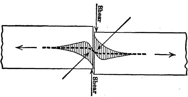
Rods are not very often placed in such a position, but where it is unavoidable, as in construction joints in the middle of slabs or beams, they serve a very good purpose; but, to obtain the best effect from them, they should be placed near the center of the slab, as in Fig. 12, and not near the top, as advocated by some writers.
If the concrete be overstressed at the points where the rod tends to bend, that is, if the rods are spaced too far apart, disintegration will follow; and, for this reason, they should be long enough to have more than 50 diameters gripped by the concrete.
This leads up to the author's seventh point, as to the overstressing of the concrete at the junction of the diagonal tension rods, or stirrups, and the bottom reinforcement.
Fig. 13.
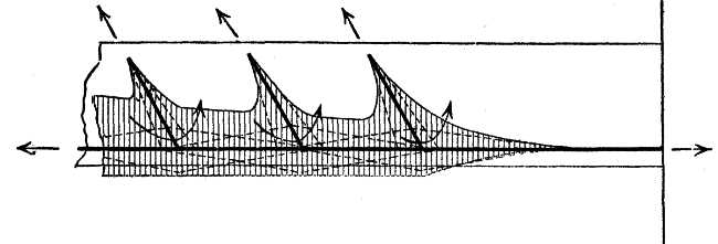
Analogous with the foregoing, it is easy to lay off the stress triangles and to find the intensity of stress at the maximum points, in fact at any point, along the tension rods and the bottom chord. This is indicated in Fig. 13. These stress triangles will start on the rod 50 diameters back from the point in question and, although the author has indicated in Fig. 1 that only two of the three rods are stressed, there must of necessity also be some stress in the bottom rod to the left of the junction, on account of the deformation which takes place in any beam due to bending. Therefore, all three rods at the point where they are joined, are under stress, and the triangles can be laid off accordingly.
It will be noticed that the concrete will resist the compressive components, not at any specific point, but all along the various rods, and with the intensities shown by the stress triangles; also, that some of these triangles will overlap, and, hence, a certain readjustment, or superimposition, of stresses takes place.
The portion which is laid off below the bottom rods will probably not act unless there is sufficient concrete below the reinforcing bars and on the sides, and, as that is not the case in ordinary construction, it is very probable, as Mr. Goodrich has pointed out, that the concrete below the rods plays an unimportant part, and that the triangle which is now shown below the rod should be partially omitted.
The triangles in Fig. 13 show the intensity of stress in the concrete at any point, or at any section where it is wanted. They show conclusively where the components are located in the concrete, their relation to the tensile stresses in the rods, and, furthermore, that they act only in a general way at right angles to one another. This is in accordance with the theory of beams, that at any point in the web there are tensile and compressive stresses of equal intensity, and at right angles to one another, although in a non-homogeneous web the distribution is somewhat different.
After having found at the point of junction the intensity of stress, it is possible to tell whether or not a bond between the stirrups and the bottom rods is necessary, and it would not seem to be where the stirrups are vertical.
It would also seem possible to tell in what direction, if any, the bend in the inclined stirrups should be made. It is to be assumed, although not expressly stated, that the bends should curve from the center up toward the end of the beam, but an inspection of the stress triangles, Fig. 13, will show that the intensity of stress is just as great on the opposite side, and it is probable that, if any bends were required to reduce the maximum stress in the concrete, they should as likely be made on the side nearest the abutment.
From the stress triangles it may also be shown that, if the stirrups were vertical instead of inclined, the stress in the concrete on both sides would be practically equal, and that, in consequence, vertical stirrups are preferable.
The next issue raised by the author is covered in his seventh point, and relates to bending moments. He states: "* * * bending moments in so-called continuous beams are juggled to reduce them to what the designer would like to have them. This has come to be almost a matter of taste, * * *."
The author seems to imply that such juggling is wrong. As a matter of fact, it is perfectly allowable and legitimate in every instance of beam or truss design, that is, from the standpoint of stress distribution, although this "juggling" is limited in practice by economical considerations.
In a series of beams supported at the ends, bending moments range from (w l2)/8 at the center of each span to zero at the supports, and, in a series of cantilevers, from zero at the center of the span to (w l2)/8 at the supports. Between these two extremes, the designer can divide, adjust, or juggle them to his heart's content, provided that in his design he makes the proper provision for the corresponding shifting of the points of contra-flexure. If that were not the case, how could ordinary bridge trusses, which have their maximum bending at the center, compare with those which, like arches, are assumed to have no bending at that point?
In his tenth point, the author proposes a method of simple designing by doing away with the complicated formulas which take account of the actual co-operation of the two materials. He states that an ideal design can be obtained in the same manner, that is, with the same formulas, as for ordinary rectangular beams; but, when he does so, he evidently fails to remember that the neutral axis is not near the center of a reinforced concrete beam under stress; in fact, with the percentage of reinforcement ordinarily used in designing—varying between three-fourths of 1% to 1-1/2%—the neutral axis, when the beam is loaded, is shifted from 26 to 10% of the beam depth above the center. Hence, a low percentage of steel reinforcement will produce a great shifting of the neutral axis, so that a design based on the formulas advocated by the author would contain either a waste of materials, an overstress of the concrete, or an understress of the steel; in fact, an error in the design of from 10 to 26 per cent. Such errors, indeed, are not to be recommended by good engineers.
The last point which the speaker will discuss is that of the elastic arch. The theory of the elastic arch is now so well understood, and it offers such a simple and, it might be said, elegant and self-checking solution of the arch design, that it has a great many advantages, and practically none of the disadvantages of other methods.
The author's statement that the segments of an arch could be made up of loose blocks and afterward cemented together, cannot be endorsed by the speaker, for, upon such cementing together, a shifting of the lines of resistance will take place when the load is applied. The speaker does not claim that arches are maintained by the cement or mortar joining the voussoirs together, but that the lines of pressure will be materially changed, and the same calculations are not applicable to both the unloaded and the loaded arch.
It is quite true, as the author states, that a few cubic yards of concrete placed in the ring will strengthen the arch more than a like amount added to the abutments, provided, however, that this material be placed properly. No good can result from an attempt to strengthen a structure by placing the reinforcing material promiscuously. This has been tried by amateurs in bridge construction, and, in such cases, the material either increased the distance from the neutral axis to the extreme fibers, thereby reducing the original section modulus, or caused a shifting of the neutral axis followed by a large bending moment; either method weakening the members it had tried to reinforce. In other words, the mere addition of material does not always strengthen a structure, unless it is placed in the proper position, and, if so placed, it should be placed all over commensurately with the stresses, that is, the unit stresses should be reduced.
The author has criticized reinforced concrete construction on the ground that the formulas and theories concerning it are not as yet fully developed. This is quite true, for the simple reason that there are so many uncertain elements which form their basis: First, the variable quantity of the modulus of elasticity, which, in the concrete, varies inversely as the stress; and, second, the fact that the neutral axis in a reinforced concrete beam under changing stress is migratory. There are also many other elements of evaluation, which, though of importance, are uncertain.
Because the formulas are established on certain assumptions is no reason for condemning them. There are, the speaker might add, few formulas in the subject of theoretical mechanics which are not based on some assumption, and as long as the variations are such that their range is known, perfectly reliable formulas can be deduced and perfectly safe structures can be built from them.
There are a great many theorists who have recently complained about the design of reinforced concrete. It seems to the speaker that such complaints can serve no useful purpose. Reinforced concrete structures are being built in steadily increasing numbers; they are filling a long needed place; they are at present rendering great service to mankind; and they are destined to cover a field of still greater usefulness. Reinforced concrete will undoubtedly show in the future that the confidence which most engineers and others now place in it is fully merited.
Harry F. Porter, Jun. Am. Soc. C. E. (by letter).—Mr. Godfrey has brought forward some interesting and pertinent points, which, in the main, are well taken; but, in his zealousness, he has fallen into the error of overpersuading himself of the gravity of some of the points he would make; on the other hand, he fails to go deeply enough into others, and some fallacies he leaves untouched. Incidentally, he seems somewhat unfair to the Profession in general, in which many earnest, able men are at work on this problem, men who are not mere theorists, but have been reared in the hard school of practical experience, where refinements of theory count for little, but common sense in design counts for much—not to mention those self-sacrificing devotees to the advancement of the art, the collegiate and laboratory investigators.
Engineers will all agree with Mr. Godfrey that there is much in the average current practice that is erroneous, much in textbooks that is misleading if not fallacious, and that there are still many designers who are unable to think in terms of the new material apart from the vestures of timber and structural steel, and whose designs, therefore, are cumbersome and impractical. The writer, however, cannot agree with the author that the practice is as radically wrong as he seems to think. Nor is he entirely in accord with Mr. Godfrey in his "constructive criticism" of those practices in which he concurs, that they are erroneous.
That Mr. Godfrey can see no use in vertical stirrups or U-bars is surprising in a practical engineer. One is prompted to ask: "Can the holder of this opinion ever have gone through the experience of placing steel in a job, or at least have watched the operation?" If so, he must have found some use for those little members which he professes to ignore utterly.
As a matter of fact, U-bars perform the following very useful and indispensable services:
(1).—If properly made and placed, they serve as a saddle in which to rest the horizontal steel, thereby insuring the correct placing of the latter during the operation of concreting, not a mean function in a type of construction so essentially practical. To serve this purpose, stirrups should be made as shown in Plate III. They should be restrained in some manner from moving when the concrete strikes them. A very good way of accomplishing this is to string them on a longitudinal rod, nested in the bend at the upper end. Mr. Godfrey, in his advocacy of bowstring bars anchored with washers and nuts at the ends, fails to indicate how they shall be placed. The writer, from experience in placing steel, thinks that it would be very difficult, if not impractical, to place them in this manner; but let a saddle of U-bars be provided, and the problem is easy.
(2).—Stirrups serve also as a tie, to knit the stem of the beam to its flange—the superimposed slab. The latter, at best, is not too well attached to the stem by the adhesion of the concrete alone, unassisted by the steel. T-beams are used very generally, because their construction has the sanction of common sense, it being impossible to cast stem and slab so that there will be the same strength in the plane at the junction of the two as elsewhere, on account of the certainty of unevenness in settlement, due to the disproportion in their depth. There is also the likelihood that, in spite of specifications to the contrary, there will be a time interval between the pouring of the two parts, and thus a plane of weakness, where, unfortunately, the forces tending to produce sliding of the upper part of the beam on the lower (horizontal shear) are a maximum. To offset this tendency, therefore, it is necessary to have a certain amount of vertical steel, disposed so as to pass around and under the main reinforcing members and reach well up into the flange (the slab), thus getting a grip therein of no mean security. The hooking of the U-bars, as shown in Plate III, affords a very effective grip in the concrete of the slab, and this is still further enhanced by the distributing or anchoring effect of the longitudinal stringing rods. Thus these longitudinals, besides serving to hold the U-bars in position, also increase their effectiveness. They serve a still further purpose as a most convenient support for the slab bars, compelling them to take the correct position over the supports, thus automatically ensuring full and proper provision for reversed stresses. More than that, they act in compression within the middle half, and assist in tension toward the ends of the span.
Thus, by using U-bars of the type indicated, in combination with longitudinal bars as described, tying together thoroughly the component parts of the beam in a vertical plane, a marked increase in stiffness, if not strength, is secured. This being the case, who can gainsay the utility of the U-bar?
Of course, near the ends, in case continuity of action is realized, whereupon the stresses are reversed, the U-bars need to be inverted, although frequently inversion is not imperative with the type of U-bar described, the simple hooking of the upper ends over the upper horizontal steel being sufficient.
As to whether or not the U-bars act with the horizontal and diagonal steel to form truss systems is relatively unessential; in all probability there is some such action, which contributes somewhat to the total strength, but at most it is of minor importance. Mr. Godfrey's points as to fallacy of truss action seem to be well taken, but his conclusions in consequence—that U-bars serve no purpose—are impractical.
The number of U-bars needed is also largely a matter of practice, although subject to calculation. Practice indicates that they should be spaced no farther apart than the effective depth of the member, and spaced closer or made heavier toward the ends, in order to keep pace with cumulating shear. They need this close spacing in order to serve as an adequate saddle for the main bars, as well as to furnish, with the lighter "stringing" rods, an adequate support to the slab bars. They should have the requisite stiffness in the bends to carry their burden without appreciable sagging; it will be found that 5/16 in. is about the minimum practical size, and that 1/2 in. is as large as will be necessary, even for very deep beams with heavy reinforcement.
If the size and number of U-bars were to be assigned by theory, there should be enough of them to care for fully 75% of the horizontal shear, the adhesion of the concrete being assumed as adequate for the remainder.
Near the ends, of course, the inclined steel, resulting from bending up some of the horizontal bars, if it is carried well across the support to secure an adequate anchorage, or other equivalent anchorage is provided, assists in taking the horizontal shear.
The embedment, too, of large stone in the body of the beam, straddling, as it were, the neutral plane, and thus forming a lock between the flange and the stem, may be considered as assisting materially in taking horizontal shear, thus relieving the U-bars. This is a factor in the strength of actual work which theory does not take into account, and by the author, no doubt, it would be regarded as insignificant; nevertheless it is being done every day, with excellent results.
The action of these various agencies—the U-bars, diagonal steel, and embedded stone—in a concrete beam, is analogous to that of bolts or keys in the case of deepened timber beams. A concrete beam may be assumed, for the purposes of illustration, to be composed of a series of superimposed layers; in this case the function of the rigid material crossing these several layers normally, and being well anchored above and below, as a unifier of the member, is obvious—it acts as so many bolts joining superimposed planks forming a beam. Of course, no such lamination actually exists, although there are always incipient forces tending to produce it; these may and do manifest themselves on occasion as an actual separation in a horizontal plane at the junction of slab and stem, ordinarily the plane of greatest weakness—owing to the method of casting—as well as of maximum horizontal shear. Beams tested to destruction almost invariably develop cracks in this region. The question then naturally arises: If U-bars serve no purpose, what will counteract these horizontal cleaving forces? On the contrary, T-beams, adequately reinforced with U-bars, seem to be safeguarded in this respect; consequently, the U-bars, while perhaps adding little to the strength, as estimated by the ultimate carrying capacity, actually must be of considerable assistance, within the limit of working loads, by enhancing the stiffness and ensuring against incipient cracking along the plane of weakness, such as impact or vibratory loads might induce. Therefore, U-bars, far from being superfluous or fallacious, are, practically, if not theoretically, indispensable.
At present there seems to be considerable diversity of opinion as to the exact nature of the stress action in a reinforced concrete beam. Unquestionably, the action in the monolithic members of a concrete structure is different from that in the simple-acting, unrestrained parts of timber or structural steel construction; because in monolithic members, by the law of continuity, reverse stresses must come into play. To offset these stresses reinforcement must be provided, or cracking will ensue where they occur, to the detriment of the structure in appearance, if not in utility. Monolithic concrete construction should be tied together so well across the supports as to make cracking under working loads impossible, and, when tested to destruction, failure should occur by the gradual sagging of the member, like the sagging of an old basket. Then, and then only, can the structure be said to be adequately reinforced.
In his advocacy of placing steel to simulate a catenary curve, with end anchorage, the author is more nearly correct than in other issues he makes. Undoubtedly, an attempt should be made in every concrete structure to approximate this alignment. In slabs it may be secured simply by elevating the bars over the supports, when, if pliable enough, they will assume a natural droop which is practically ideal; or, if too stiff, they may be bent to conform approximately to this position. In slabs, too, the reinforcement may be made practically continuous, by using lengths covering several spans, and, where ends occur, by generous lapping. In beams the problem is somewhat more complicated, as it is impossible, except rarely, to bow the steel and to extend it continuously over several supports; but all or part of the horizontal steel can be bent up at about the quarter point, carried across the supports into the adjacent spans, and anchored there by bending it down at about the same angle as it is bent up on the approach, and then hooking the ends.
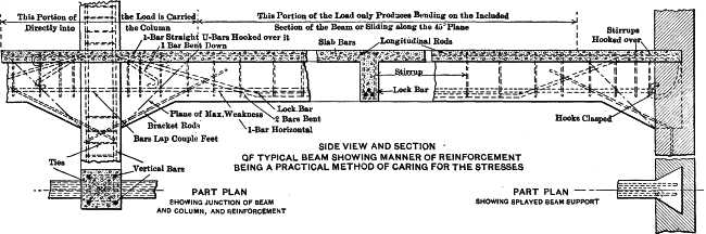
Plate III.—Junction of Beam and Wall Column. Reinforcement in Place in Beam, Lintel, and Slab up to Beam. Note End Anchorage of Beam Bars.
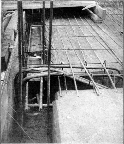
It is seldom necessary to adopt the scheme proposed by the author, namely, a threaded end with a bearing washer and a nut to hold the washer in place, although it is sometimes expedient, but not absolutely necessary, in end spans, where prolongation into an adjacent span is out of the question. In end spans it is ordinarily sufficient to give the bars a double reverse bend, as shown in Plate III, and possibly to clasp hooks with the horizontal steel. If steel be placed in this manner, the catenary curve will be practically approximated, the steel will be fairly developed throughout its length of embedment, and the structure will be proof against cracking. In this case, also, there is much less dependence on the integrity of the bond; in fact, if there were no bond, the structure would still develop most of its strength, although the deflection under heavy loading might be relatively greater.
The writer once had an experience which sustains this point. On peeling off the forms from a beam reinforced according to the method indicated, it was found that, because of the crowding together of the bars in the bottom, coupled with a little too stiff a mixture, the beam had hardly any concrete on the underside to grip the steel in the portion between the points of bending up, or for about the middle half of the member; consequently, it was decided to test this beam. The actual working load was first applied and no deflection, cracking, or slippage of the bars was apparent; but, as the loading was continued, deflection set in and increased rapidly for small increments of loading, a number of fine cracks opened up near the mid-section, which extended to the neutral plane, and the steel slipped just enough, when drawn taut, to destroy what bond there was originally, owing to the contact of the concrete above. At three times the live load, or 450 lb. per sq. ft., the deflection apparently reached a maximum, being about 5/16 in. for a clear distance, between the supports, of 20 ft.; and, as the load was increased to 600 lb. per sq. ft., there was no appreciable increase either in deflection or cracking; whereupon, the owner being satisfied, the loading was discontinued. The load was reduced in amount to three times the working load (450 lb.) and left on over night; the next morning, there being no detectable change, the beam was declared to be sound. When the load was removed the beam recovered all but about 1/8 in. of its deflection, and then repairs were made by attaching light expanded metal to the exposed bars and plastering up to form. Although nearly three years have elapsed, there have been no unfavorable indications, and the owner, no doubt, has eased his mind entirely in regard to the matter. This truly remarkable showing can only be explained by the catenary action of the main steel, and some truss action by the steel which was horizontal, in conjunction with the U-bars, of which there were plenty. As before noted, the clear span was 20 ft., the width of the bay, 8 ft., and the size under the slab (which was 5 in. thick) 8 by 18 in. The reinforcement consisted of three 1-1/8-in. round medium-steel bars, with 3/8-in. U-bars placed the effective depth of the member apart and closer toward the supports, the first two or three being 6 in. apart, the next two or three, 9 in., the next, 12 in., etc., up to a maximum, throughout the mid-section, of 15 in. Each U-bar was provided with a hook at its upper end, as shown in Plate III, and engaged the slab reinforcement, which in this case was expanded metal. Two of the 1-1/8-in. bars were bent up and carried across the support. At the point of bending up, where they passed the single horizontal bar, which was superimposed, a lock-bar was inserted, by which the pressure of the bent-up steel against the concrete, in the region of the bend, was taken up and distributed along the horizontal bar. This feature is also shown in Fig. 14. The bars, after being carried across the support, were inclined into the adjacent span and provided with a liberal, well-rounded hook, furnishing efficient anchorage and provision for reverse stresses. This was at one end only, for—to make matters worse—the other end was a wall bearing; consequently, the benefit of continuity was denied. The bent-up bars were given a double reverse bend, as already described, carrying them around, down, in, and up, and ending finally by clasping them in the hook of the horizontal bar. This apparently stiffened up the free end, for, under the test load, its action was similar to that of the completely restrained end, thus attesting the value of this method of end-fixing.
The writer has consistently followed this method of reinforcement, with unvaryingly good results, and believes that, in some measure, it approximates the truth of the situation. Moreover, it is economical, for with the bars bent up over the supports in this manner, and positively anchored, plenty of U-bars being provided, it is possible to remove the forms with entire safety much sooner than with the ordinary methods which are not as well stirruped and only partially tied across the supports. It is also possible to put the structure into use at an earlier date. Failure, too, by the premature removal of the centers, is almost impossible with this method. These considerations more than compensate for the trouble and expense involved in connection with such reinforcement. The writer will not attempt here a theoretical analysis of the stresses incurred in the different parts of this beam, although it might be interesting and instructive.
Fig. 14.
The concrete, with the reinforcement disposed as described, may be regarded as reposing on the steel as a saddle, furnishing it with a rigid jacket in which to work, and itself acting only as a stiff floor and a protecting envelope. Bond, in this case, while, of course, an adjunct, is by no means vitally important, as is generally the case with beams unrestrained in any way and in which the reinforcement is not provided with adequate end anchorage, in which case a continuous bond is apparently—at any rate, theoretically—indispensable.
An example of the opposite extreme in reinforced concrete design, where provision for reverse stresses was almost wholly lacking, is shown in the Bridgeman Brothers' Building, in Philadelphia, which collapsed while the operation of casting the roof was in progress, in the summer of 1907. The engineering world is fairly familiar with the details of this disaster, as they were noted both in the lay and technical press. In this structure, not only were U-bars almost entirely absent, but the few main bars which were bent up, were stopped short over the support. The result was that the ties between the rib and the slab, and also across the support, being lacking, some of the beams, the forms of which had been removed prematurely, cracked of their own dead weight, and, later, when the roof collapsed, owing to the deficient bracing of the centers, it carried with it each of the four floors to the basement, the beams giving way abruptly over the supports. Had an adequate tie of steel been provided across the supports, the collapse, undoubtedly, would have stopped at the fourth floor. So many faults were apparent in this structure, that, although only half of it had fallen, it was ordered to be entirely demolished and reconstructed.
The cracks in the beams, due to the action of the dead weight alone, were most interesting, and illuminative of the action which takes place in a concrete beam. They were in every case on the diagonal, at an angle of approximately 45°, and extended upward and outward from the edge of the support to the bottom side of the slab. Never was the necessity for diagonal steel, crossing this plane of weakness, more emphatically demonstrated. To the writer—an eye-witness—the following line of thought was suggested:
Should not the concrete in the region above the supports and for a distance on either side, as encompassed by the opposed 45° lines (Fig. 14), be regarded as abundantly able, of and by itself, and without reinforcing, to convey all its load into the column, leaving only the bending to be considered in the truncated portion intersected? Not even the bending should be considered, except in the case of relatively shallow members, but simply the tendency on the part of the wedge-shaped section to slip out on the 45° planes, thereby requiring sufficient reinforcement at the crossing of these planes of principal weakness to take the component of the load on this portion, tending to shove it out. This reinforcement, of course, should be anchored securely both ways; in mid-span by extending it clear through, forming a suspensory, and, in the other direction, by prolonging it past the supports, the concrete, in this case, along these planes, being assumed to assist partly or not at all.
This would seem to be a fair assumption. In all events, beams designed in this manner and checked by comparison with the usual methods of calculation, allowing continuity of action, are found to agree fairly well. Hence, the following statement seems to be warranted: If enough steel is provided, crossing normally or nearly so the 45° planes from the edge of the support upward and outward, to care for the component of the load on the portion included within a pair of these planes, tending to produce sliding along the same, and this steel is adequately anchored both ways, there will be enough reinforcement for every other purpose. In addition, U-bars should be provided for practical reasons.
The weak point of beams, and slabs also, fully reinforced for continuity of action, is on the under side adjacent to the edge of the support, where the concrete is in compression. Here, too, the amount of concrete available is small, having no slab to assist it, as is the case within the middle section, where the compression is in the top. Over the supports, for the width of the column, there is abundant strength, for here the steel has a leverage equal to the depth of the column; but at the very edge and for at least one-tenth of the span out, conditions are serious. The usual method of strengthening this region is to subpose brackets, suitably proportioned, to increase the available compressive area to a safe figure, as well as the leverage of the steel, at the same time diminishing the intensity of compression. Brackets, however, are frequently objectionable, and are therefore very generally omitted by careless or ignorant designers, no especial compensation being made for their absence. In Europe, especially in Germany, engineers are much more careful in this respect, brackets being nearly always included. True, if brackets are omitted, some compensation is provided by the strengthening which horizontal bars may give by extending through this region, but sufficient additional compressive resistance is rarely afforded thereby. Perhaps the best way to overcome the difficulty, without resorting to brackets, is to increase the compressive resistance of the concrete, in addition to extending horizontal steel through it. This may be done by hooping or by intermingling scraps of iron or bits of expanded metal with the concrete, thereby greatly increasing its resistance. The experiments made by the Department of Bridges of the City of New York, on the value of nails in concrete, in which results as high as 18,000 lb. per sq. in. were obtained, indicate the availability of this device; the writer has not used it, nor does he know that it has been used, but it seems to be entirely rational, and to offer possibilities.
Another practical test, which indicates the value of proper reinforcement, may be mentioned. In a storage warehouse in Canada, the floor was designed, according to the building laws of the town, for a live load of 150 lb. per sq. ft., but the restrictions being more severe than the standard American practice, limiting the lever arm of the steel to 75% of the effective depth, this was about equivalent to a 200-lb. load in the United States. The structure was to be loaded up to 400 or 500 lb. per sq. ft. steadily, but the writer felt so confident of the excess strength provided by his method of reinforcing that he was willing to guarantee the structure, designed for 150 lb., according to the Canadian laws, to be good for the actual working load. Plain, round, medium-steel bars were used. A 10-ft. panel, with a beam of 14-ft. span, and a slab 6 in. thick (not including the top coat), with 1/2-in. round bars, 4 in. on centers, was loaded to 900 lb. per sq. ft., at which load no measurable deflection was apparent. The writer wished to test it still further, but there was not enough cement—the material used for loading. The load, however, was left on for 48 hours, after which, no sign of deflection appearing, not even an incipient crack, it was removed. The total area of loading was 14 by 20 ft. The beam was continuous at one end only, and the slab only on one side. In other parts of the structure conditions were better, square panels being possible, with reinforcement both ways, and with continuity, both of beams and slabs, virtually in every direction, end spans being compensated by shortening. The method of reinforcing was as before indicated. The enormous strength of the structure, as proved by this test, and as further demonstrated by its use for nearly two years, can only be explained on the basis of the continuity of action developed and the great stiffness secured by liberal stirruping. Steel was provided in the middle section according to the rule, (w l)/8, the span being taken as the clear distance between the supports; two-thirds of the steel was bent up and carried across the supports, in the case of the beams, and three-fourths of the slab steel was elevated; this, with the lap, really gave, on the average, four-thirds as much steel over the supports as in the center, which, of course, was excessive, but usually an excess has to be tolerated in order to allow for adequate anchorage. Brackets were not used, but extra horizontal reinforcement, in addition to the regular horizontal steel, was laid in the bottom across the supports, which, seemingly, was satisfactory. The columns, it should be added, were calculated for a very low value, something like 350 lb. per sq. in., in order to compensate for the excess of actual live load over and above the calculated load.
This piece of work was done during the winter, with the temperature almost constantly at +10° and dropping below zero over night. The precautions observed were to heat the sand and water, thaw out the concrete with live steam, if it froze in transporting or before it was settled in place, and as soon as it was placed, it was decked over and salamanders were started underneath. Thus, a job equal in every respect to warm-weather installation was obtained, it being possible to remove the forms in a fortnight.
Plate IV, Fig. 1.—Slab and Beam Reinforcement Continuous Over Supports. Span of Beams = 14 Ft. Span of Slabs = 12 Ft. Slab, 6 In. Thick.
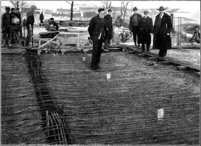
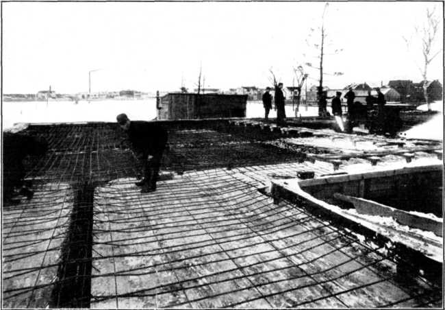
Plate IV, Fig. 2.—Reinforcement in Place Over One Complete Floor of Storage Warehouse. Slabs, 14 Ft. Square. Reinforced Two Ways. Note Continuity of Reinforcement and Elevation Over Supports. Floor Designed for 150 Lb. per Sq. Ft. Live Load. Tested to 900 Lb. per Sq. Ft.
In another part of this job (the factory annex) where, owing to the open nature of the structure, it was impossible to house it in as well as the warehouse which had bearing walls to curtain off the sides, less fortunate results were obtained. A temperature drop over night of nearly 50°, followed by a spell of alternate freezing and thawing, effected the ruin of at least the upper 2 in. of a 6-in. slab spanning 12 ft. (which was reinforced with 1/2-in. round bars, 4 in. on centers), and the remaining 4 in. was by no means of the best quality. It was thought that this particular bay would have to be replaced. Before deciding, however, a test was arranged, supports being provided underneath to prevent absolute failure. But as the load was piled up, to the extent of nearly 400 lb. per sq. ft., there was no sign of giving (over this span) other than an insignificant deflection of less than 1/4 in., which disappeared on removing the load. This slab still performs its share of the duty, without visible defect, hence it must be safe. The question naturally arises: if 4 in. of inferior concrete could make this showing, what must have been the value of the 6 in. of good concrete in the other slabs? The reinforcing in the slab, it should be stated, was continuous over several supports, was proportioned for (w l)/8 for the clear span (about 11 ft.), and three-fourths of it was raised over the supports. This shows the value of the continuous method of reinforcing, and the enormous excess of strength in concrete structures, as proportioned by existing methods, when the reverse stresses are provided for fully and properly, though building codes may make no concession therefor.
Another point may be raised, although the author has not mentioned it, namely, the absurdity of the stresses commonly considered as occurring in tensile steel, 16,000 lb. per sq. in. for medium steel being used almost everywhere, while some zealots, using steel with a high elastic limit, are advocating stresses up to 22,000 lb. and more; even the National Association of Cement Users has adopted a report of the Committee on Reinforced Concrete, which includes a clause recommending the use of 20,000 lb. on high steel. As theory indicates, and as F.E. Turneaure, Assoc. M. Am. Soc. C. E., of the University of Wisconsin, has proven by experiment, failure of the concrete encircling the steel under tension occurs when the stress in the steel is about 5,000 lb. per sq. in. It is evident, therefore, that if a stress of even 16,000 lb. were actually developed, not to speak of 20,000 lb. or more, the concrete would be so replete with minute cracks on the tension side as to expose the embedded metal in innumerable places. Such cracks do not occur in work because, under ordinary working loads, the concrete is able to carry the load so well, by arch and dome action, as to require very little assistance from the steel, which, consequently, is never stressed to a point where cracking of the concrete will be induced. This being the case, why not recognize it, modify methods of design, and not go on assuming stresses which have no real existence?
The point made by Mr. Godfrey in regard to the fallacy of sharp bends is patent, and must meet with the agreement of all who pause to think of the action really occurring. This is also true of his points as to the width of the stem of T-beams, and the spacing of bars in the same. As to elastic arches, the writer is not sufficiently versed in designs of this class to express an opinion, but he agrees entirely with the author in his criticism of retaining-wall design. What the author proposes is rational, and it is hard to see how the problem could logically be analyzed otherwise. His point about chimneys, however, is not as clear.
As to columns, the writer agrees with Mr. Godfrey in many, but not in all, of his points. Certainly, the fallacy of counting on vertical steel to carry load, in addition to the concrete, has been abundantly shown. The writer believes that the sole legitimate function of vertical steel, as ordinarily used, is to reinforce the member against flexure, and that its very presence in the column, unless well tied across by loops of steel at frequent intervals, so far from increasing the direct carrying capacity, is a source of weakness. However, the case is different when a large amount of rigid vertical steel is used; then the steel may be assumed to carry all the load, at the value customary in structural steel practice, the concrete being considered only in the light of fire-proofing and as affording lateral support to the steel, increasing its effective radius of gyration and thus its safe carrying capacity. In any event the load should be assumed to be carried either by the concrete or by the steel, and, if by the former, the longitudinal and transverse steel which is introduced should be regarded as auxiliary only. Vertical steel, if not counted in the strength, however, may on occasion serve a very useful practical purpose; for instance, the writer once had a job where, owing to the collection of ice and snow on a floor, which melted when the salamanders were started, the lower ends of several of the superimposed columns were eaten away, with the result that when the forms were withdrawn, these columns were found to be standing on stilts. Only four 1-in. bars were present, looped at intervals of about 1 ft., in a column 12 ft. in length and having a girth of 14 in., yet they were adequate to carry both the load of the floor above and the load incidental to construction. If no such reinforcement had been provided, however, failure would have been inevitable. Thus, again, it is shown that, where theory and experiment may fail to justify certain practices, actual experience does, and emphatically.
Mr. Godfrey is absolutely right in his indictment of hooping as usually done, for hoops can serve no purpose until the concrete contained therein is stressed to incipient rupture; then they will begin to act, to furnish restraint which will postpone ultimate failure. Mr. Godfrey states that, in his opinion, the lamina of concrete between each hoop is not assisted; but, as a matter of fact, practically regarded, it is, the coarse particles of the aggregate bridging across from hoop to hoop; and if—as is the practice of some—considerable longitudinal steel is also used, and the hoops are very heavy, so that when the bridging action of the concrete is taken into account, there is in effect a very considerable restraining of the concrete core, and the safe carrying capacity of the column is undoubtedly increased. However, in the latter case, it would be more logical to consider that the vertical steel carried all the load, and that the concrete core, with the hoops, simply constituted its rigidity and the medium of getting the load into the same, ignoring, in this event, the direct resistance of the concrete.
What seems to the writer to be the most logical method of reinforcing concrete columns remains to be developed; it follows along the lines of supplying tensile resistance to the mass here and there throughout, thus creating a condition of homogeneity of strength. It is precisely the method indicated by the experiments already noted, made by the Department of Bridges of the City of New York, whereby the compressive resistance of concrete was enormously increased by intermingling wire nails with it. Of course, it is manifestly out of the question, practically and economically, to reinforce column concrete in this manner, but no doubt a practical and an economical method will be developed which will serve the same purpose. The writer knows of one prominent reinforced concrete engineer, of acknowledged judgment, who has applied for a patent in which expanded metal is used to effect this very purpose; how well this method will succeed remains to be seen. At any rate, reinforcement of this description seems to be entirely rational, which is more than can be said for most of the current standard types.
Mr. Godfrey's sixteenth point, as to the action in square panels, seems also to the writer to be well taken; he recollects analyzing Mr. Godfrey's narrow-strip method at the time it appeared in print, and found it rational, and he has since had the pleasure of observing actual tests which sustained this view. Reinforcement can only be efficient in two ways, if the span both ways is the same or nearly so; a very little difference tends to throw the bulk of the load the short way, for stresses know only one law, namely, to follow the shortest line. In square panels the maximum bending comes on the mid-strips; those adjacent to the margin beams have very little bending parallel to the beam, practically all the action being the other way; and there are all gradations between. The reinforcing, therefore, should be spaced the minimum distance only in the mid-region, and from there on constantly widened, until, at about the quarter point, practically none is necessary, the slab arching across on the diagonal from beam to beam. The practice of spacing the bars at the minimum distance throughout is common, extending the bars to the very edge of the beams. In this case about half the steel is simply wasted.
In conclusion, the writer wishes to thank Mr. Godfrey for his very able paper, which to him has been exceedingly illuminative and fully appreciated, even though he has been obliged to differ from its contentions in some respects. On the other hand, perhaps, the writer is wrong and Mr. Godfrey right; in any event, if, through the medium of this contribution to the discussion, the writer has assisted in emphasizing a few of the fundamental truths; or if, in his points of non-concordance, he is in coincidence with the views of a sufficient number of engineers to convince Mr. Godfrey of any mistaken stands; or, finally, if he has added anything new to the discussion which may help along the solution, he will feel amply repaid for his time and labor. The least that can be said is that reform all along the line, in matters of reinforced concrete design, is insistent.
John Stephen Sewell, M. Am. Soc. C. E. (by letter).—The author is rather severe on the state of the art of designing reinforced concrete. It appears to the writer that, to a part of the indictment, at least, a plea of not guilty may properly be entered; and that some of the other charges may not be crimes, after all. There is still room for a wide difference of opinion on many points involved in the design of reinforced concrete, and too much zeal for conviction, combined with such skill in special pleading as this paper exhibits, may possibly serve to obscure the truth, rather than to bring it out clearly.
Point 1.—This is one to which the proper plea is "not guilty." The writer does not remember ever to have seen just the type of construction shown in Fig. 1, either used or recommended. The angle at which the bars are bent up is rarely as great as 45°, much less 60 degrees. The writer has never heard of "sharp bends" being insisted on, and has never seen them used; it is simply recommended or required that some of the bars be bent up and, in practice, the bend is always a gentle one. The stress to be carried by the concrete as a queen-post is never as great as that assumed by the author, and, in practice, the queen-post has a much greater bearing on the bars than is indicated in Fig. 1.
Point 2.—The writer, in a rather extensive experience, has never seen this point exemplified.
Point 3.—It is probable that as far as Point 3 relates to retaining walls, it touches a weak spot sometimes seen in actual practice, but necessity for adequate anchorage is discussed at great length in accepted literature, and the fault should be charged to the individual designer, for correct information has been within his reach for at least ten years.
Point 4.—In this case it would seem that the author has put a wrong interpretation on what is generally meant by shear. However, it is undoubtedly true that actual shear in reinforcing steel is sometimes figured and relied on. Under some conditions it is good practice, and under others it is not. Transverse rods, properly placed, can surely act in transmitting stress from the stem to the flange of a T-beam, and could properly be so used. There are other conditions under which the concrete may hold the rods so rigidly that their shearing strength may be utilized; where such conditions do not obtain, it is not ordinarily necessary to count on the shearing strength of the rods.
Point 5.—Even if vertical stirrups do not act until the concrete has cracked, they are still desirable, as insuring a gradual failure and, generally, greater ultimate carrying capacity. It would seem that the point where their full strength should be developed is rather at the neutral axis than at the centroid of compression stresses. As they are usually quite light, this generally enables them to secure the requisite anchorage in the compressed part of the concrete. Applied to a riveted truss, the author's reasoning would require that all the rivets by which web members are attached to the top chord should be above the center of gravity of the chord section.
Point 6.—There are many engineers who, accepting the common theory of diagonal tension and compression in a solid beam, believe that, in a reinforced concrete beam with stirrups, the concrete can carry the diagonal compression, and the stirrups the tension. If these web stresses are adequately cared for, shear can be neglected.
The writer cannot escape the conclusion that tests which have been made support the above belief. He believes that stirrups should be inclined at an angle of 45° or less, and that they should be fastened rigidly to the horizontal bars; but that is merely the most efficient way to use them—not the only way to secure the desired action, at least, in some degree.
The author's proposed method of bending up some of the main bars is good, but he should not overlook the fact that he is taking them away from the bottom of the beam just as surely as in the case of a sharp bend, and this is one of his objections to the ordinary method of bending them up. Moreover, with long spans and varying distances of the load, the curve which he adopts for his bars cannot possibly be always the true equilibrium curve. His concrete must then act as a stiffening truss, and will almost inevitably crack before his cable can come into action as such.
Bulletin No. 29 of the University of Illinois contains nothing to indicate that the bars bent up in the tests reported were bent up in any other than the ordinary way; certainly they could not be considered as equivalent to the cables of a suspension bridge. These beams behaved pretty well, but the loads were applied so as to make them practically queen-post trusses, symmetrically loaded. While the bends in the bars were apparently not very sharp, and the angle of inclination was much less than 60°, or even 45°, it is not easy to find adequate bearings for the concrete posts on theoretical grounds, yet it is evident that the bearing was there just the same. The last four beams of the series, 521-1, 521-2, 521-5, 521-6, were about as nearly like Fig. 1 as anything the writer has ever seen in actual practice, yet they seem to have been the best of all. To be sure, the ends of the bent-up bars had a rather better anchorage, but they seem to have managed the shear question pretty much according to the expectation of their designer, and it is almost certain that the latter's assumptions would come under some part of the author's general indictment. These beams would seem to justify the art in certain practices condemned by the author. Perhaps he overlooked them.
Point 7.—The writer does not believe that the "general" practice as to continuity is on the basis charged. In fact, the general practice seems to him to be rather in the reverse direction. Personally, the writer believes in accepting continuity and designing for it, with moments at both center and supports equal to two-thirds of the center movement for a single span, uniformly loaded. He believes that the design of reinforced concrete should not be placed on the same footing as that of structural steel, because there is a fundamental difference, calling for different treatment. The basis should be sound, in both cases; but what is sound for one is not necessarily so for the other. In the author's plan for a series of spans designed as simple beams, with a reasonable amount of top reinforcement, he might get excessive stress and cracks in the concrete entirely outside of the supports. The shear would then become a serious matter, but no doubt the direct reinforcement would come into play as a suspension bridge, with further cracking of the concrete as a necessary preliminary.
Unfortunately, the writer is unable to refer to records, but he is quite sure that, in the early days, the rivets and bolts in the upper part of steel and iron bridge stringer connections gave some trouble by failing in tension due to continuous action, where the stringers were of moderate depth compared to the span. Possibly some members of the Society may know of such instances. The writer's instructors in structural design warned him against shallow stringers on that account, and told him that such things had happened.
Is it certain that structural steel design is on such a sound basis after all? Recent experiences seem to cast some doubt on it, and we may yet discover that we have escaped trouble, especially in buildings, because we almost invariably provide for loads much greater than are ever actually applied, and not because our knowledge and practice are especially exact.
Point 8.—The writer believes that this point is well taken, as to a great deal of current practice; but, if the author's ideas are carried out, reinforced concrete will be limited to a narrow field of usefulness, because of weight and cost. With attached web members, the writer believes that steel can be concentrated in heavy members in a way that is not safe with plain bars, and that, in this way, much greater latitude of design may be safely allowed.
Point 9.—The writer is largely in accord with the author's ideas on the subject of T-beams, but thinks he must have overlooked a very careful and able analysis of this kind of member, made by A.L. Johnson, M. Am. Soc. C. E., a number of years ago. While too much of the floor slab is still counted on for flange duty, it seems to the writer that, within the last few years, practice has greatly improved in this respect.
Point 10.—The author's statement regarding the beam and slab formulas in common use is well grounded. The modulus of elasticity of concrete is so variable that any formulas containing it and pretending to determine the stress in the concrete are unreliable, but the author's proposed method is equally so. We can determine by experiment limiting percentages of steel which a concrete of given quality can safely carry as reinforcement, and then use empirical formulas based on the stress in the steel and an assumed percentage of its depth in the concrete as a lever arm with more ease and just as much accuracy. The common methods result in designs which are safe enough, but they pretend to determine the stress in concrete; the writer does not believe that that is possible within 30% of the truth, and can see no profit in making laborious calculations leading to such unreliable results.
Point 11.—The writer has never designed a reinforced concrete chimney, but if he ever has to do so, he will surely not use any formula that is dependent on the modulus of elasticity of concrete.
Points 12, 13, and 14.—The writer has never had to consider these points to any extent in his own work, and will leave discussion to those better qualified.
Point 15.—There is much questionable practice in regard to reinforced concrete columns; but the matter is hardly disposed of as easily as indicated by the author. Other engineers draw different conclusions from the tests cited by the author, and from some to which he does not refer. To the writer it appears that here is a problem still awaiting solution on a really satisfactory basis. It seems incredible that the author would use plain concrete in columns, yet that seems to be the inference. The tests seem to indicate that there is much merit in both hooping and longitudinal reinforcement, if properly designed; that the fire-resisting covering should not be integral with the columns proper; that the high results obtained by M. Considère in testing small specimens cannot be depended on in practice, but that the reinforcement is of great value, nevertheless. The writer believes that when load-carrying capacity, stresses due to eccentricity, and fire-resisting qualities are all given due consideration, a type of column with close hooping and longitudinal reinforcement provided with shear members, will finally be developed, which will more than justify itself.
Point 16.—The writer has not gone as deeply into this question, from a theoretical point of view, as he would like; but he has had one experience that is pertinent. Some years ago, he built a plain slab floor supported by brick walls. The span was about 16 ft. The dimensions of the slab at right angles to the reinforcement was 100 ft. or more. Plain round bars, 1/2 in. in diameter, were run at right angles to the reinforcement about 2 ft. on centers, the object being to lessen cracks. The reinforcement consisted of Kahn bars, reaching from wall to wall. The rounds were laid on top of the Kahn bars. The concrete was frozen and undeniably damaged, but the floors stood up, without noticeable deflection, after the removal of the forms. The concrete was so soft, however, that a test was decided on. An area about 4 ft. wide, and extending to within about 1 ft. of each bearing wall, was loaded with bricks piled in small piers not in contact with each other, so as to constitute practically a uniformly distributed load. When the total load amounted to much less than the desired working load for the 4-ft. strip, considerable deflection had developed. As the load increased, the deflection increased, and extended for probably 15 or 20 ft. on either side of the loaded area. Finally, under about three-fourths of the desired breaking load for the 4-ft. strip, it became evident that collapse would soon occur. The load was left undisturbed and, in 3 or 4 min., an area about 16 ft. square tore loose from the remainder of the floor and fell. The first noticeable deflection in the above test extended for 8 or 10 ft. on either side of the loaded strip. It would seem that this test indicated considerable distributing power in the round rods, although they were not counted as reinforcement for load-carrying purposes at all. The concrete was extremely poor, and none of the steel was stressed beyond the elastic limit. While this test may not justify the designer in using lighter reinforcement for the short way of the slab, it at least indicates a very real value for some reinforcement in the other direction. It would seem to indicate, also, that light steel members in a concrete slab might resist a small amount of shear. The slab in this case was about 6 in. thick.
Sanford E. Thompson, M. Am. Soc. C. E. (by letter).—Mr. Godfrey's sweeping condemnation of reinforced concrete columns, referred to in his fifteenth point, should not be passed over without serious criticism. The columns in a building, as he states, are the most vital portion of the structure, and for this very reason their design should be governed by theoretical and practical considerations based on the most comprehensive tests available.
The quotation by Mr. Godfrey from a writer on hooped columns is certainly more radical than is endorsed by conservative engineers, but the best practice in column reinforcement, as recommended by the Joint Committee on Concrete and Reinforced Concrete, which assumes that the longitudinal bars assist in taking stress in accordance with the ratio of elasticity of steel to concrete, and that the hooping serves to increase the toughness of the column, is founded on the most substantial basis of theory and test.
In preparing the second edition of "Concrete, Plain and Reinforced," the writer examined critically the various tests of concrete columns in order to establish a definite basis for his conclusions. Referring more particularly to columns reinforced with vertical steel bars, an examination of all the tests of full-sized columns made in the United States appears to bear out the fact very clearly that longitudinal steel bars embedded in concrete increase the strength of the column, and, further, to confirm the theory by which the strength of the combination of steel and concrete may be computed and is computed in practice.
Tests of large columns have been made at the Watertown Arsenal, the Massachusetts Institute of Technology, the University of Illinois, by the City of Minneapolis, and at the University of Wisconsin. The results of these various tests were recently summarized by the writer in a paper presented at the January, 1910, meeting of the National Association of Cement Users[O]. Reference may be made to this paper for fuller particulars, but the averages of the tests of each series are worth repeating here.
In comparing the averages of reinforced columns, specimens with spiral or other hooping designed to increase the strength, or with horizontal reinforcement placed so closely together as to prevent proper placing of the concrete, are omitted. For the Watertown Arsenal tests the averages given are made up from fair representative tests on selected proportions of concrete, given in detail in the paper referred to, while in other cases all the corresponding specimens of the two types are averaged. The results are given in Table 1.
The comparison of these tests must be made, of course, independently in each series, because the materials and proportions of the concrete and the amounts of reinforcement are different in the different series. The averages are given simply to bring out the point, very definitely and distinctly, that longitudinally reinforced columns are stronger than columns of plain concrete.
A more careful analysis of the tests shows that the reinforced columns are not only stronger, but that the increase in strength due to the reinforcement averages greater than the ordinary theory, using a ratio of elasticity of 15, would predicate.
Certain of the results given are diametrically opposed to Mr. Godfrey's conclusions from the same sets of tests. Reference is made by him, for example (page 69), to a plain column tested at the University of Illinois, which crushed at 2,001 lb. per sq. in., while a reinforced column of similar size crushed at 1,557 lb. per sq. in.,[P] and the author suggests that "This is not an isolated case, but appears to be the rule." Examination of this series of tests shows that it is somewhat more erratic than most of those made at the University of Illinois, but, even from the table referred to by Mr. Godfrey, pursuing his method of reasoning, the reverse conclusion might be reached, for if, instead of selecting, as he has done, the weakest reinforced column in the entire lot and the strongest plain column, a reverse selection had been made, the strength of the plain column would have been stated as 1,079 lb. per sq. in. and that of the reinforced column as 3,335 lb. per sq. in. If extremes are to be selected at all, the weakest reinforced column should be compared with the weakest plain column, and the strongest reinforced column with the strongest plain column; and the results would show that while an occasional reinforced column may be low in strength, an occasional plain column will be still lower, so that the reinforcement, even by this comparison, is of marked advantage in increasing strength. In such cases, however, comparisons should be made by averages. The average strength of the reinforced columns, even in this series, as given in Table 1, is considerably higher than that of the plain columns.
TABLE 1.—Average Results of Tests of Plain vs. Longitudinally Reinforced Columns.
Location of test. Average strength of plain columns. Average strength of longitudinally reinforced columns. Reference.
Watertown Arsenal. 1,781 2,992 Taylor and Thompson's "Concrete, Plain and Reinforced" (2nd edition), p. 493.
Massachusetts Institute of Technology. 1,750 2,370 Transactions, Am. Soc. C. E., Vol. L, p. 487.
University of Illinois. 1,550 1,750 Bulletin No. 10. University of Illinois, 1907.
City of Minneapolis. 2,020 2,300 Engineering News, Dec. 3d, 1908, p. 608.
University of Wisconsin. 2,033 2,438 Proceedings, Am. Soc. for Testing Materials, Vol. IX, 1909, p. 477.
In referring, in the next paragraph, to Mr. Withey's tests at the University of Wisconsin, Mr. Godfrey selects for his comparison two groups of concrete which are not comparable. Mr. Withey, in the paper describing the tests, refers to two groups of plain concrete columns, A1 to A4, and W1 to W3. He speaks of the uniformity in the tests of the former group, the maximum variation in the four specimens being only 2%, but states, with reference to columns, W1 to W3, that:
"As these 3 columns were made of a concrete much superior to that in any of the other columns made from 1:2:4 or 1:2:3-1/2 mix, they cannot satisfactorily be compared with them. Failures of all plain columns were sudden and without any warning."
Now, Mr. Godfrey, instead of taking columns A1 to A3, selects for his comparison W1 to W3, made, as Mr. Withey distinctly states, with an especially superior concrete. Taking columns, A1 to A3, for comparison with the reinforced columns, E1 to E3, the result shows an average of 2,033 for the plain columns and 2,438 for the reinforced columns.
Again, taking the third series of tests referred to by Mr. Godfrey, those at Minneapolis, Minn., it is to be noticed that he selects for his criticism a column which has this note as to the manner of failure: "Bending at center (bad batch of concrete at this point)." Furthermore, the column is only 9 by 9 in., and square, and the stress referred to is calculated on the full section of the column instead of on the strength within the hooping, although the latter method is the general practice in a hooped column. The inaccuracy of this is shown by the fact that, with this small size of square column, more than half the area is outside the hooping and never taken into account in theoretical computations. A fair comparison, as far as longitudinal reinforcement is concerned, is always between the two plain columns and the six columns, E, D, and F. The results are so instructive that a letter[Q] by the writer is quoted in full as follows:
"Sir:—
"In view of the fact that the column tests at Minneapolis, as reported in your paper of December 3, 1908, p. 608, are liable because of the small size of the specimens to lead to divergent conclusions, a few remarks with reference to them may not be out of place at this time.
"1. It is evident that the columns were all smaller, being only 9 in. square, than is considered good practice in practical construction, because of the difficulty of properly placing the concrete around the reinforcement.
"2. The tests of columns with flat bands, A, B, and C, in comparison with the columns E, D and F, indicate that the wide bands affected the placing of the concrete, separating the internal core from the outside shell so that it would have been nearly as accurate to base the strength upon the material within the bands, that is, upon a section of 38 sq. in., instead of upon the total area of 81 sq. in. This set of tests, A, B and C, is therefore inconclusive except as showing the practical difficulty in the use of bands in small columns, and the necessity for disregarding all concrete outside of the bands when computing the strength.
"3. The six columns E, D and F, each of which contained eight 5/8-in. rods, are the only ones which are a fair test of columns longitudinally reinforced, since they are the only specimens except the plain columns in which the small sectional area was not cut by bands or hoops. Taking these columns, we find an average strength 38% in excess of the plain columns, whereas, with the percentage of reinforcement used, the ordinary formula for vertical steel (using a ratio of elasticity of steel to concrete of 15) gives 34% as the increase which might be expected. In other words, the actual strength of this set of columns was in excess of the theoretical strength. The wire bands on these columns could not be considered even by the advocates of hooped columns as appreciably adding to the strength, because they were square instead of circular. It may be noted further in connection with these longitudinally reinforced columns that the results were very uniform and, further, that the strength of every specimen was much greater than the strength of the plain columns, being in every case except one at least 40% greater. In these columns the rods buckled between the bands, but they evidently did not do so until their elastic limit was passed, at which time of course they would be expected to fail.
"4. With reference to columns, A, B, C and L, which were essentially hooped columns, the failure appears to have been caused by the greater deformation which is always found in hooped columns, and which in the earlier stages of the loading is apparently due to lack of homogeneity caused by the difficulty in placing the concrete around the hooping, and in the later stage of the loading to the excessive expansion of the concrete. This greater deformation in a hooped column causes any vertical steel to pass its elastic limit at an earlier stage than in a column where the deformation is less, and therefore produces the buckling between the bands which is noted in these two sets of columns. This excessive deformation is a strong argument against the use of high working stresses in hooped columns.
"In conclusion, then, it may be said that the columns reinforced with vertical round rods showed all the strength that would be expected of them by theoretical computation. The hooped columns, on the other hand, that is, the columns reinforced with circular bands and hoops, gave in all cases comparatively low results, but no conclusions can be drawn from them because the unit-strength would have been greatly increased if the columns had been larger so that the relative area of the internal core to the total area of the column had been greater."
From this letter, it will be seen that every one of Mr. Godfrey's comparisons of plain versus reinforced columns requires explanations which decidedly reduce, if they do not entirely destroy, the force of his criticism.
This discussion can scarcely be considered complete without brief reference to the theory of longitudinal steel reinforcement for columns. The principle[R] is comparatively simple. When a load is placed on a column of any material it is shortened in proportion, within working limits, to the load placed upon it; that is, with a column of homogeneous material, if the load is doubled, the amount of shortening or deformation is also doubled. If vertical steel bars are embedded in concrete, they must shorten when the load is applied, and consequently relieve the concrete of a portion of its load. It is therefore physically impossible to prevent such vertical steel from taking a portion of the load unless the steel slips or buckles.
As to the possible danger of the bars in the concrete slipping or buckling, to which Mr. Godfrey also refers, again must tests be cited. If the ends are securely held—and this is always the case when bars are properly butted or are lapped for a sufficient length—they cannot slip. With reference to buckling, tests have proved conclusively that vertical bars such as are used in columns, when embedded in concrete, will not buckle until the elastic limit of the steel is reached, or until the concrete actually crushes. Beyond these points, of course, neither steel nor concrete nor any other material is expected to do service.
As proof of this statement, it will be seen, by reference to tests at the Watertown Arsenal, as recorded in "Tests of Metals," that many of the columns were made with vertical bar reinforcement having absolutely no hoops or horizontal steel placed around them. That is, the bars, 8 ft. long, were placed in the four corners of the column—in some tests only 2 in. from the surface—and held in place simply by the concrete itself.[S] There was no sign whatever of buckling until the compression was so great that the elastic limit of the steel was passed, when, of course, no further strength could be expected from it.
To recapitulate the conclusions reached as a result of a study of the tests: It is evident that, not only does theory permit the use of longitudinal bar reinforcement for increasing the strength of concrete columns, whenever such reinforcement is considered advisable, but that all the important series of column tests made in the United States to date show a decisive increase in strength of columns reinforced with longitudinal steel bars over those which are not reinforced. Furthermore, as has already been mentioned, without treating the details of the proof, it can be shown that the tests bear out conclusively the conservatism of computing the value of the vertical steel bars in compression by the ordinary formulas based on the ratio of the moduli of elasticity of steel to concrete.
Edward Godfrey, M. Am. Soc. C. E. (by letter).—As was to be expected, this paper has brought out discussion, some of which is favorable and flattering; some is in the nature of dust-throwing to obscure the force of the points made; some would attempt to belittle the importance of these points; and some simply brings out the old and over-worked argument which can be paraphrased about as follows: "The structures stand up and perform their duty, is this not enough?"
The last-mentioned argument is as old as Engineering; it is the "practical man's" mainstay, his "unanswerable argument." The so-called practical man will construct a building, and test it either with loads or by practical use. Then he will modify the design somewhere, and the resulting construction will be tested. If it passes through this modifying process and still does service, he has something which, in his mind, is unassailable. Imagine the freaks which would be erected in the iron bridge line, if the capacity to stand up were all the designer had to guide him, analysis of stresses being unknown. Tests are essential, but analysis is just as essential. The fact that a structure carries the bare load for which it is computed, is in no sense a test of its correct design; it is not even a test of its safety. In Pittsburg, some years ago, a plate-girder span collapsed under the weight of a locomotive which it had carried many times. This bridge was, perhaps, thirty years old. Some reinforced concrete bridges have failed under loads which they have carried many times. Others have fallen under no extraneous load, and after being in service many months. If a large number of the columns of a structure fall shortly after the forms are removed, what is the factor of safety of the remainder, which are identical, but have not quite reached their limit of strength? Or what is the factor of safety of columns in other buildings in which the concrete was a little better or the forms have been left in a little longer, both sets of columns being similarly designed?
There are highway bridges of moderately long spans standing and doing service, which have 2-in. chord pins; laterals attached to swinging floor-beams in such a way that they could not possibly receive their full stress; eye-bars with welded-on heads; and many other equally absurd and foolish details, some of which were no doubt patented in their day. Would any engineer with any knowledge whatever of bridge design accept such details? They often stand the test of actual service for years; in pins, particularly, the calculated stress is sometimes very great. These details do not stand the test of analysis and of common sense, and, therefore, no reputable engineer would accept them.
Mr. Turner, in the first and second paragraphs of his discussion, would convey the impression that the writer was in doubt as to his "personal opinions" and wanted some free advice. He intimates that he is too busy to go fully into a treatise in order to set them right. He further tries to throw discredit on the paper by saying that the writer has adduced no clean-cut statement of fact or tests in support of his views. If Mr. Turner had read the paper carefully, he would not have had the idea that in it the hooped column is condemned. As to this more will be said later. The paper is simply and solely a collection of statements of facts and tests, whereas his discussion teems with his "personal opinion," and such statements as "These values * * * are regarded by the writer as having at least double the factor of safety used in ordinary designs of structural steel"; "On a basis not far from that which the writer considers reasonable practice." Do these sound like clean-cut statements of fact, or are they personal opinions? It is a fact, pure and simple, that a sharp bend in a reinforcing rod in concrete violates the simplest principles of mechanics; also that the queen-post and Pratt and Howe truss analogies applied to reinforcing steel in concrete are fallacies; that a few inches of embedment will not anchor a rod for its value; that concrete shrinks in setting in air and puts initial stress in both the concrete and the steel, making assumed unstressed initial conditions non-existent. It is a fact that longitudinal rods alone cannot be relied on to reinforce a concrete column. Contrary to Mr. Turner's statement, tests have been adduced to demonstrate this fact. Further, it is a fact that the faults and errors in reinforced concrete design to which attention is called, are very common in current design, and are held up as models in nearly all books on the subject.
The writer has not asked any one to believe a single thing because he thinks it is so, or to change a single feature of design because in his judgment that feature is faulty. The facts given are exemplifications of elementary mechanical principles overlooked by other writers, just as early bridge designers and writers on bridge design overlooked the importance of calculating bridge pins and other details which would carry the stress of the members.
A careful reading of the paper will show that the writer does not accept the opinions of others, when they are not backed by sound reason, and does not urge his own opinion.
Instead of being a statement of personal opinion for which confirmation is desired, the paper is a simple statement of facts and tests which demonstrate the error of practices exhibited in a large majority of reinforced concrete work and held up in the literature on the subject as examples to follow. Mr. Turner has made no attempt to deny or refute any one of these facts, but he speaks of the burden of proof resting on the writer. Further, he makes statements which show that he fails entirely to understand the facts given or to grasp their meaning. He says that the writer's idea is "that the entire pull of the main reinforcing rod should be taken up apparently at the end." He adds that the soundness of this position may be questioned, because, in slabs, the steel frequently breaks at the center. Compare this with the writer's statement, as follows:
"In shallow beams there is little need of provision for taking shear by any other means than the concrete itself. The writer has seen a reinforced slab support a very heavy load by simple friction, for the slab was cracked close to the supports. In slabs, shear is seldom provided for in the steel reinforcement. It is only when beams begin to have a depth approximating one-tenth of the span that the shear in the concrete becomes excessive and provision is necessary in the steel reinforcement. Years ago, the writer recommended that, in such beams, some of the rods be curved up toward the ends of the span and anchored over the support."
It is solely in providing for shear that the steel reinforcement should be anchored for its full value over the support. The shear must ultimately reach the support, and that part which the concrete is not capable of carrying should be taken to it solely by the steel, as far as tensile and shear stresses are concerned. It should not be thrown back on the concrete again, as a system of stirrups must necessarily do.
The following is another loose assertion by Mr. Turner:
"Mr. Godfrey appears to consider that the hooping and vertical reinforcement of columns is of little value. He, however, presents for consideration nothing but his opinion of the matter, which appears to be based on an almost total lack of familiarity with such construction."
There is no excuse for statements like this. If Mr. Turner did not read the paper, he should not have attempted to criticize it. What the writer presented for consideration was more than his opinion of the matter. In fact, no opinion at all was presented. What was presented was tests which prove absolutely that longitudinal rods without hoops may actually reduce the strength of a column, and that a column containing longitudinal rods and "hoops which are not close enough to stiffen the rods" may be of less strength than a plain concrete column. A properly hooped column was not mentioned, except by inference, in the quotation given in the foregoing sentence. The column tests which Mr. Turner presents have no bearing whatever on the paper, for they relate to columns with bands and close spirals. Columns are sometimes built like these, but there is a vast amount of work in which hooping and bands are omitted or are reduced to a practical nullity by being spaced a foot or so apart.
A steel column made up of several pieces latticed together derives a large part of its stiffness and ability to carry compressive stresses from the latticing, which should be of a strength commensurate with the size of the column. If it were weak, the column would suffer in strength. The latticing might be very much stronger than necessary, but it would not add anything to the strength of the column to resist compression. A formula for the compressive strength of a column could not include an element varying with the size of the lattice. If the lattice is weak, the column is simply deficient; so a formula for a hooped column is incorrect if it shows that the strength of the column varies with the section of the hoops, and, on this account, the common formula is incorrect. The hoops might be ever so strong, beyond a certain limit, and yet not an iota would be added to the compressive strength of the column, for the concrete between the hoops might crush long before their full strength was brought into play. Also, the hoops might be too far apart to be of much or any benefit, just as the lattice in a steel column might be too widely spaced. There is no element of personal opinion in these matters. They are simply incontrovertible facts. The strength of a hooped column, disregarding for the time the longitudinal steel, is dependent on the fact that thin discs of concrete are capable of carrying much more load than shafts or cubes. The hoops divide the column into thin discs, if they are closely spaced; widely spaced hoops do not effect this. Thin joints of lime mortar are known to be many times stronger than the same mortar in cubes. Why, in the many books on the subject of reinforced concrete, is there no mention of this simple principle? Why do writers on this subject practically ignore the importance of toughness or tensile strength in columns? The trouble seems to be in the tendency to interpret concrete in terms of steel. Steel at failure in short blocks will begin to spread and flow, and a short column has nearly the same unit strength as a short block. The action of concrete under compression is quite different, because of the weakness of concrete in tension. The concrete spalls off or cracks apart and does not flow under compression, and the unit strength of a shaft of concrete under compression has little relation to that of a flat block. Some years ago the writer pointed out that the weakness of cast-iron columns in compression is due to the lack of tensile strength or toughness in cast iron. Compare 7,600 lb. per sq. in. as the base of a column formula for cast iron with 100,000 lb. per sq. in. as the compressive strength of short blocks of cast iron. Then compare 750 lb. per sq. in., sometimes used in concrete columns, with 2,000 lb. per sq. in., the ultimate strength in blocks. A material one-fiftieth as strong in compression and one-hundredth as strong in tension with a "safe" unit one-tenth as great! The greater tensile strength of rich mixtures of concrete accounts fully for the greater showing in compression in tests of columns of such mixtures. A few weeks ago, an investigator in this line remarked, in a discussion at a meeting of engineers, that "the failure of concrete in compression may in cases be due to lack of tensile strength." This remark was considered of sufficient novelty and importance by an engineering periodical to make a special news item of it. This is a good illustration of the state of knowledge of the elementary principles in this branch of engineering.
Mr. Turner states, "Again, concrete is a material which shows to the best advantage as a monolith, and, as such, the simple beam seems to be decidedly out of date to the experienced constructor." Similar things could be said of steelwork, and with more force. Riveted trusses are preferable to articulated ones for rigidity. The stringers of a bridge could readily be made continuous; in fact, the very riveting of the ends to a floor-beam gives them a large capacity to carry reverse moments. This strength is frequently taken advantage of at the end floor-beam, where a tie is made to rest on a bracket having the same riveted connection as the stringer. A small splice-plate across the top flanges of the stringers would greatly increase this strength to resist reverse moments. A steel truss span is ideally conditioned for continuity in the stringers, since the various supports are practically relatively immovable. This is not true in a reinforced concrete building where each support may settle independently and entirely vitiate calculated continuous stresses. Bridge engineers ignore continuity absolutely in calculating the stringers; they do not argue that a simple beam is out of date. Reinforced concrete engineers would do vastly better work if they would do likewise, adding top reinforcement over supports to forestall cracking only. Failure could not occur in a system of beams properly designed as simple spans, even if the negative moments over the supports exceeded those for which the steel reinforcement was provided, for the reason that the deflection or curving over the supports can only be a small amount, and the simple-beam reinforcement will immediately come into play.
Mr. Turner speaks of the absurdity of any method of calculating a multiple-way reinforcement in slabs by endeavoring to separate the construction into elementary beam strips, referring, of course, to the writer's method. This is misleading. The writer does not endeavor to "separate the construction into elementary beam strips" in the sense of disregarding the effect of cross-strips. The "separation" is analogous to that of considering the tension and compression portions of a beam separately in proportioning their size or reinforcement, but unitedly in calculating their moment. As stated in the paper, "strips are taken across the slab and the moment in them is found, considering the limitations of the several strips in deflection imposed by those running at right angles therewith." It is a sound and rational assumption that each strip, 1 ft. wide through the middle of the slab, carries its half of the middle square foot of the slab load. It is a necessary limitation that the other strips which intersect one of these critical strips across the middle of the slab, cannot carry half of the intercepted square foot, because the deflection of these other strips must diminish to zero as they approach the side of the rectangle. Thus, the nearer the support a strip parallel to that support is located, the less load it can take, for the reason that it cannot deflect as much as the middle strip. In the oblong slab the condition imposed is equal deflection of two strips of unequal span intersecting at the middle of the slab, as well as diminished deflection of the parallel strips.
In this method of treating the rectangular slab, the concrete in tension is not considered to be of any value, as is the case in all accepted methods.
Some years ago the writer tested a number of slabs in a building, with a load of 250 lb. per sq. ft. These slabs were 3 in. thick and had a clear span of 44 in. between beams. They were totally without reinforcement. Some had cracked from shrinkage, the cracks running through them and practically the full length of the beams. They all carried this load without any apparent distress. If these slabs had been reinforced with some special reinforcement of very small cross-section, the strength which was manifestly in the concrete itself, might have been made to appear to be in the reinforcement. Magic properties could be thus conjured up for some special brand of reinforcement. An energetic proprietor could capitalize tension in concrete in this way and "prove" by tests his claims to the magic properties of his reinforcement.
To say that Poisson's ratio has anything to do with the reinforcement of a slab is to consider the tensile strength of concrete as having a positive value in the bottom of that slab. It means to reinforce for the stretch in the concrete and not for the tensile stress. If the tensile strength of concrete is not accepted as an element in the strength of a slab having one-way reinforcement, why should it be accepted in one having reinforcement in two or more directions? The tensile strength of concrete in a slab of any kind is of course real, when the slab is without cracks; it has a large influence in the deflection; but what about a slab that is cracked from shrinkage or otherwise?