FURTHER DEVELOPMENTS IN THE TELEGRAPHIC DIRECTION.
Reading edition
SYNTONIC TELEGRAPHY.
In the present state of the law in this country it appears to be necessary for a scientific man whose investigations may have any practical bearing to refrain from communicating his work to any scientific society, or publishing it in any journal until he has registered it and paid a fee to the Government under the so-called Patent Law. This unfortunate system is well calculated to prevent scientific men in general from giving any attention to practical applications, and to deter them from an attempt to make their researches useful to the community. If a scientific worker publishes in the natural way, no one has any rights in the thing published; it is given away and lies useless, for no one will care to expend capital upon a thing over which he has no effective control. In this case practical developments generally wait until some outsider steps in and either patents some slight addition or modification, or else, as sometimes happens, patents the whole thing, with some slight addition. If a scientific worker refrains from publishing and himself takes out a patent, there are innumerable troubles and possible litigation ahead of him, at least if the thing turns out at all remunerative; but the probability is that, in his otherwise occupied hands, it will not so turn out until the period of his patent right has expired.
Pending a much-to-be-desired emendation of the law, whereby the courts can take cognisance of discoveries or fundamental steps in an invention communicated to and officially dated by a responsible scientific society, and can thereafter award to the discoverer such due and moderate recompense as shall seem appropriate when a great industry has risen on the basis of that same discovery or fundamental invention—pending this much-to-be-desired modification of the law, it appears to be necessary to go through the inappropriate and repulsive form of registering a claim to an attempt at a monopoly. The instinct of the scientific worker is to publish everything, to hope that any useful aspect of it may be as quickly as possible utilised, and to trust to the instinct for fair play that he shall not be the loser when the thing becomes commercially profitable. To grant him a monopoly is to grant him a more than doubtful boon; to grant him the privilege of fighting for his monopoly is to grant him a pernicious privilege, which will sap his energy, waste his time, and destroy his power of future production.
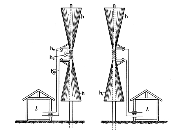
Fig. 24
(Fig. 5 of Specification 11,575/97).—Syntonic Radiator, adapted for sending and for receiving.
However, the author, in consultation with friends, decided that registration was, under present conditions, necessary, and, accordingly, for his attempt at syntony and other improvements in the Hertz wave method of signalling, he can refer here to certain patents taken out, in conjunction chiefly with Dr. Alexander Muirhead, his co-worker, which are numbered respectively as follows:—
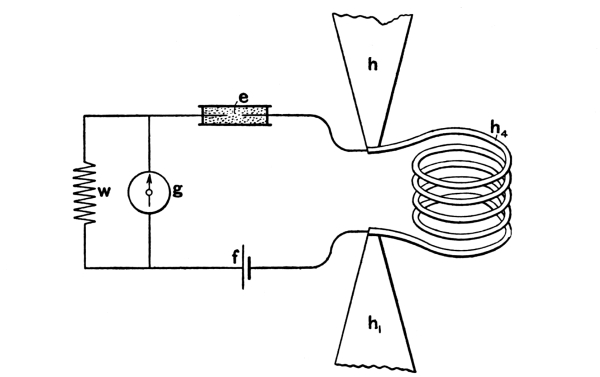
Fig. 25
(Fig. 13 of Specification 11,575/97).—Diagram of connections for Syntonic Receiver; e being coherer and w a non-inductive conducting or capacity shunt, to eliminate the self-induction of the receiving instrument.
(1) 11,575 of 1897, wherein is described the general syntonic principle and the mode of prolonging the duration of the vibrations emitted by a radiator or by a receiver. This is done by adding to it electromagnetic inertia (that is, a self-induction coil) in such a way as to lessen its radiating power, converting its type of emission from something like a whip-crack into something more like that of a struck string. (Not pushing it so far as to make it like a fork, though that could be done if desired: see Journal Inst.E.E., December, 1898.) But too prolonged a duration of vibration is not desirable, for it can only be obtained at the expense of radiating power. For the most distant signalling the single pulse or whip-crack is the best, and this is what in practice has hitherto always been employed; but, with it, tuning is of course impossible. A radiator with several swings is less violent at its first impulse than is a momentary emitter; but then the lessened emitting power of a radiator is to be compensated by a correspondingly prolonged duration of vibration on the part of the receiver or absorber, thus rendering the radiator susceptible of tuning to a special similarly-tuned receiver or resonator. The tuned resonator is then to respond, not to the first impulse of the radiator, but to a rapidly worked up succession of properly timed impulses; so that at length, after an accumulation of two or three, or perhaps four, swings, the electrostatic charges in its terminal plates become sufficient to overflow and spit off into the coherer, thereby effecting its stimulation and giving the signal. A resonator not properly tuned—i.e., one tuned to some different frequency of vibration—would not be able to accumulate impulses, and hence would not respond, unless of course it were so much too near the radiator that the very first swing stimulated it sufficiently to disturb the coherer; in which case, again, there is no room for tuning. The two points to attend to for syntonic discrimination are: (a) that the receiver shall not be so near the emitter as to feel its impulses too easily, i.e., without accumulation; (b) that the properly tuned receiver shall be so arranged that it can work up and accumulate the impulses of the radiator, and before attaining its maximum swing can overflow into the coherer associated with it and thus give the signal.
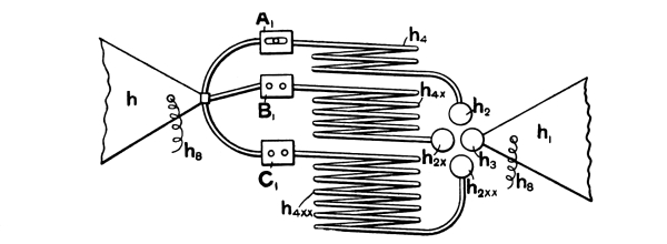
Fig. 26
(Fig. 10 of Specification 11,575/97).—Interchangeable Self-Induction Coils for signalling to different stations.
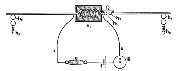
Fig. 27
(Fig. 3 of Specification 11,575/97).—Diagrammatic representation of Syntonic Radiator and Receiver. The middle spark gap h2 h3 is unnecessary, though sometimes helpful. The main charging is done by impulsive rush at the outside knobs.
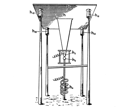
Fig. 28
(Fig. 7 of Specification 11,575/97).—Syntonic Radiator with earth connection arranged for sending.
The general appearance of a pair of signalling stations on this plan is shown in Fig. 24, where the huts contain the sending and receiving instruments. The self-induction coil joining the two capacity-areas is better depicted in Fig. 25, which also shows one mode of joining up the coherer to a syntonic receiver. (The galvanometer and shunt are, of course, merely typical of any kind of telegraphic instrument whatever.) Fig. 26 indicates one form of sender with three alternative syntonising coils for speaking to three distant attuned stations. Fig. 27 shows a radiator arranged for receiving, but illustrates another method of charging, and one frequently employed by the author, viz., the method by impulsive rush (compare Figs. 11, 12 and 19, on pp. 14 and 25 of this book). The terminals of the Ruhmkorff coil are here connected, not to the capacity-areas direct, but to a pair of knobs near the centre of gravity of each area, so that when the discharge occurs each area is suddenly charged oppositely, and the two opposite charges are left to surge into one another and set up the oscillations. This impulsive method of charging is essentially that adopted in the spherical whip-crack emitter depicted in Fig. 19 (p. 25, ante), the two poles of the sphere having but small capacity and being joined by as thick a conductor as the equator of the sphere. But for such a radiator as is indicated in Fig. 24 or Fig. 27 the author commonly found that a third short spark gap in the middle was an improvement, and so, as is well known, did Prof. Righi find it, and embodied it in his well-known double-sphere double-knob emitter.
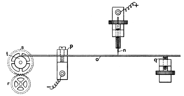
Fig. 29
(Fig. 12 of Specification 11,575/97).—Single-point Coherer, with clockwork Tapper-back operating on the projecting end of the spring clamped at P and lightly touching a needle point n.
The specification also contains figures of earth-connected forms of radiators, with or without self-induction coils, of which Fig. 28 may be here reproduced; and likewise a modification of the point coherer depicted in Fig. 17, on page 22 (see Fig. 29, and also fig. on page 27), where the spiral wire spring is replaced by a piece of straight watch-spring, clamped at one end, adjusted by a screw at the other, and lightly touched by a needle point at its middle; a very gentle tapping back stimulus being provided in the form of a clockwork or other mechanically-driven motor grazing lightly against one end of the spring protruding beyond the clamp for the purpose.
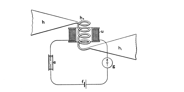
Fig. 30
(Fig. 14 of Specification 11,575/97).—Another diagram of connections for Syntonic Receiver, with Coherer in a secondary or transformer circuit; a conducting or a capacity shunt for the telegraphic instrument being applicable as before.
Figs. 31 and 32
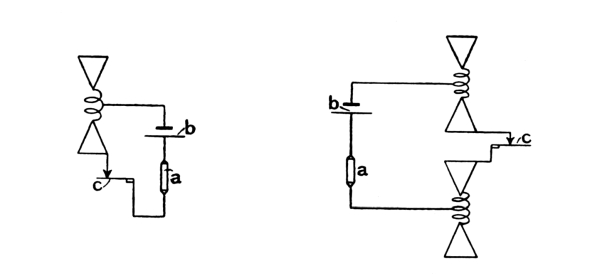
(Figs. 5 and 6 of Specification 18,644/97).—Modes of connecting a Coherer to one or to a pair of Syntonic Radiators so that it may feel their electrostatic disturbance.
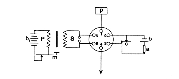
Fig. 33
(Fig. 11 of Specification 18,644/97).—Actual connections for a Sending and Receiving Station on the plan shown in Fig. 37. Left-hand side shows spark sending, right-hand side shows Coherer receiving.
Fig. 30 shows a coherer inserted in a secondary or transformer circuit, and operated inductively by the oscillations of the receiver, which are thus transformed up and raised in potential.
(2) No. 16,405, 1897, wherein are described chiefly various practical methods of decohering, by means of cams and otherwise, which are appropriate when working rapidly with automatic transmitter and siphon recorder.
(3) No. 18,644, 1897, represents different ways of connecting up a coherer to a syntonic resonator, so as to get the benefit of its overflow without interfering with the working up of the electric oscillations, e.g., Figs. 31, 32 and 33. It also shows a plan for constantly decohering by a rapidly revolving cam a number of coherers in parallel, so that one at least is always ready to receive an impulse (Fig. 34). Further, it arranges to utilise the earth or a cable sheath, or other uninsulated conductor, for the purpose of conveying electric impulses to a distance (Figs. 35, 36, 37 and 38). And next it is arranged to assist the coherer to feel the full effect of any electric jerk by shunting out the battery and galvanometer, which are necessarily in series with it, by means of a condenser of moderate capacity (Fig. 35), which also shows a self-induction mode of sending a stimulus along an uninsulated line. This condenser obstructs all steady currents, such as give the signal, but it transmits freely any momentary electric impulses, such as stimulate a coherer.
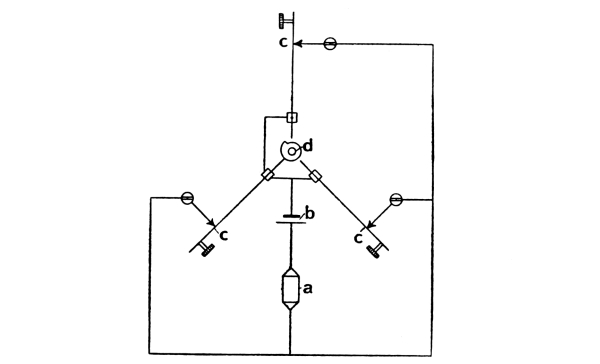
Fig. 34
(Fig. 1 of Specification 18,644/97).—Single-point Coherers in parallel, with successive decoherence.
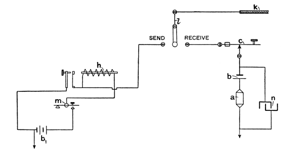
Fig. 35
(Fig. 3 of Specification 18,644/97).—A self-induction method of sending jerks into a badly insulated line, and arrangement for detecting such jerks by a single-point Coherer.
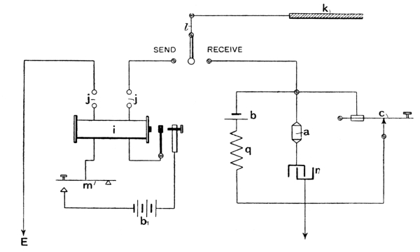
Fig. 36
(Fig. 4 of Specification 18,644/97).—Another arrangement for sending jerks into a bare or badly insulated line, and connections for Coherer detection.
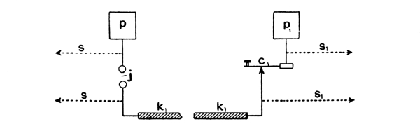
Fig. 37
(Fig. 10 of Specification 18,644/97).—Another mode of sending a jerk from a spark gap at j into a badly insulated cable or other conductor, which is connected at the other end to a Coherer, the circuit being completed inductively through the air by means of the areas p, p1. The dotted lines s represent the switch connection of Fig. 33.
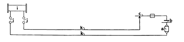
38
(Fig. 13 of Specification 18,644/97).—Another method of signalling through a pair of imperfect conductors, such as gas and water pipes i, without the above elevated inductive connection.
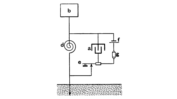
Fig. 39
(Fig. 3 of Specification 29,069/97).—Diagram of Coherer connection to Syntonic Collector, with capacity shunt for telegraphic instrument.
(4) No. 29,069, 1897. In this patent various methods of connecting up the shunting condenser, whose object it is to transmit all jerks undiluted to the coherer, are shown, all adapted to work with a syntonic resonator (Fig. 39). There is also shown a complete switch (Fig. 40) for effecting the transition from “sending” to “receiving,” exposing the coherer to the full effect of the distant radiator, and completely protecting and isolating it from its home radiator; the switch being so arranged that signalling is impossible unless the home coherer is protected. A rotating commutator is also shown, whose object is to expose the coherer to the full influence of a receiver, especially of a non-syntonic receiver or simple collector, without its being shunted or otherwise interfered with by the telegraphic apparatus; to which, however, immediately afterwards the rotating commutator connects it, and then effects the tapping back.
Connections are shown (Fig. 41) for a complete sending and receiving station on this plan with a syntonic radiator and resonator indicated (though not to scale). But with syntonic resonators the revolving commutator method is not found to be necessary; the sending and receiving switch, together with the closed box for protecting the coherer in an instantly accessible manner is therefore the chief feature of this diagram.
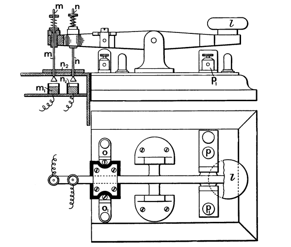
Fig. 40
(Fig. 6 of Specification 29,069/97).—Switch at a Sending and Receiving Station, to change all the connections with a protected Coherer from receiving to sending by depressing the knob l.
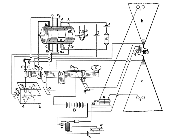
Fig. 41
(Fig. 7 of Specification 29,069/97).—Diagram of connections at a protected Coherer Station with Syntonic Radiator and Collector.
Earlier Telegraphic Advances.
In April, 1895, a communication was made to the Russian Physical Society by Prof. A. Popoff, of the Torpedo School, Cronstadt, Russia, and appears in the Journal of that Society for January, 1896. In this communication the use of an elevated wire and of a tapper-back worked through a relay by the coherer current are clearly described, and signalling was effected for a distance of 5 kilometres (3½ miles).
An extract from this communication is given in The Electrician for December, 1897, Vol. XL., page 235, and from it we reproduce Fig. 42, illustrating the tapping back arrangement.
The following extracts from this paper may also be quoted:—
“On using a sensitive relay in the circuit with the coherer tube, and an ordinary electric bell in the other circuit of the relay, for sound signals and as an automatic tapper for the coherer, I obtain an apparatus which exactly answers every electric wave by a short ring, and by rhythmical strokes if electric vibrations be excited continuously.”
“On connecting an electromagnetic recorder in parallel with the bell, tracing a straight line along the paper band which is moved by a 12-hour clockwork cylinder, I obtain an instrument registering by a cross line on the moving band every electric wave that reaches the coherer from across the atmosphere. Such an apparatus was placed at the Meteorological Observatory at St. Petersburg in July, 1895, one of the electrodes of the coherer being connected by an insulated wire with an ordinary lightning conductor, the other electrode of the tube-coherer being connected with the ground.”
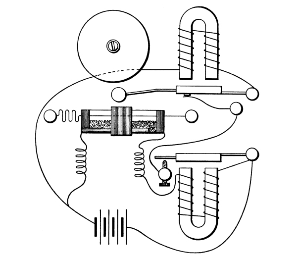
Fig. 42
(Fig. 2 on p. 235 of The Electrician, Vol. XL.).—Method of automatic tapping back by relay current employed for telegraphy by Prof. Popoff in 1895.
Prof. Popoff then goes on to say that his apparatus works well as a lightning recorder, and that he hopes it can be used for signalling to great distances. He says:—
“I can detect waves at the distance of one kilometre if I employ as sender a Hertz vibrator with 30 centimetre spheres, and if I use the ordinary Siemens relay; but with a Bjerknes vibrator 90 centimetres diameter, and a more sensitive relay, I reach five kilometres of good working.”
Thus it is plain that Prof. Popoff employed the elevated wire as receiver in 1895, but did not employ it as sender.
In 1897 Prof. Slaby, of Berlin, published (in German) a book called “Spark Telegraphy,” in which he described his success in signalling from 3 to 13 miles across land. From this book we take the following illustrations of the coherer and its connections:—
Fig. 43 shows the coherer tied on to a glass tube, by which it is supported.
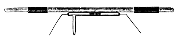
Fig. 43 (Fig. 7 of Slaby’s book).
Fig. 44 shows the simplest form of its connection to a one-cell battery A and a polarised relay B, which switches on another battery of several cells a operating the Morse instrument or electric bell or sounder b and also the tapper-back c, the hammer of which raps gently on the coherer tube at every signal.
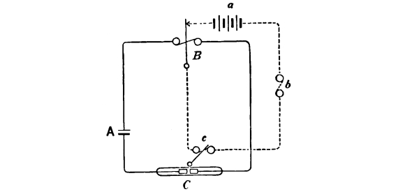
Fig. 44 (Fig. 8 of Slaby’s book).—
Slaby’s arrangement of Coherer and of tapper-back and relay connections.
The actual apparatus is depicted in two views, Figs. 45 and 46, where will be recognised on the left-hand side the coherer and tapper-back; in the middle the batteries, both for relay and for coherer circuits; and on the right-hand side a relay and the signalling or calling instrument, in this case shown as an ordinary electric bell.
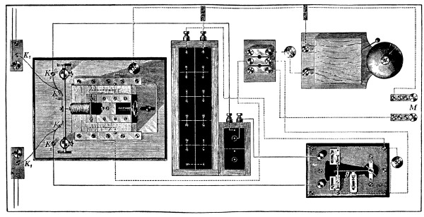
Fig. 45 (Fig. 16 of Slaby’s book).—
View of Slaby’s Receiving Apparatus, with call-bell rung by relay, or with Morse instrument joined on to terminals M, and switch to change from Calling to Signalling. K K are the terminals of elevated wire and earth, and the Coherer and Tapper-back are close to them.
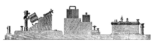
Fig. 46 (Fig. 17 of Prof. Slaby’s book).—
An elevation view of Prof. Slaby’s same Apparatus, showing the electromagnet and hammer of the tapper-back worked by relay current from local battery, as in Popoff’s plan of 1895.
A Morse instrument is to be connected to the terminals M, and either it or the bell can be switched into the circuit at pleasure. The form of relay depicted is special to Slaby, but the rest of the arrangements are practically identical with those shown by Marconi at Dover.
Fig. 47 gives a diagram of the actual connections.
Fig. 48 is a picture of one of Slaby’s signalling stations, showing the way the elevated wire enters the building.
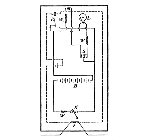
Fig. 47 (Fig. 19 of “Spark Telegraphy”).—
Diagram of Slaby’s connections in the above apparatus. F is the coherer and K the tapper-back.
During September, 1899, the Marconi method of signalling to long distances was demonstrated before the British Association at Dover. The chief feature of the installation was the elevated wire supported by a mast, and terminating at the top in a small conductor, which is usually made of wire netting, and is suspended from an insulating rod. The lower end of this elevated wire passed into the building through an aperture, and was connected to one terminal of the usual Ruhmkorff coil, the other terminal of which was earthed. The signalling key was of the simplest description, being nothing more than a well-insulated Morse key worked by hand and causing a make-and-break in the primary circuit of the coil. The ordinary trembling break of the induction coil was at work in the usual way, so that while the signalling key was depressed continuously there was a torrent of sparks between the knobs of the secondary. This method of signalling was identical with that employed by everyone since the time of Hertz, except that, instead of connecting the secondary terminals to two insulated plates, one was now connected to earth and the other to a small insulated conductor at considerable elevation.
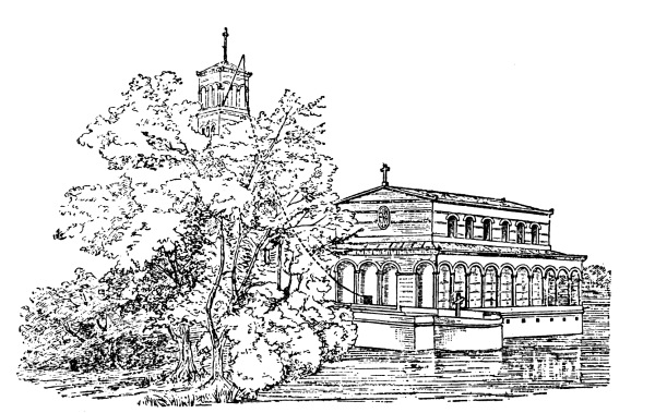
Fig. 48 (Fig. 11 of Prof. Slaby’s book on “Spark Telegraphy”).
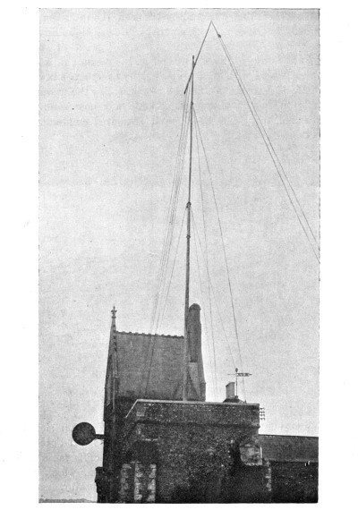
Fig. 49 (p. 762, The Electrician, Vol. XLIII.).—
Marconi Signalling Mast at Dover Town Hall.
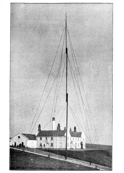
Fig. 50 (Fig. 1, p. 7, The Electrician, Vol. XLIII.).—
Mast at South Foreland; from which Signals went to a similar Mast at Wimereux, near Boulogne.
From this mast in the town of Dover (Fig. 49) signals could be sent to another loftier mast at the South Foreland (Fig. 50), where it is itself elevated by chalk cliffs far above the sea. From this South Foreland station, which was similar in all essential respects to the Dover station, except that its elevation was greater, messages could be sent and received to and from a station near Boulogne, on the coast of France, and to and from the East Goodwins lightship. The signalling was slow, but appeared dependable, and the simplicity of all the arrangements was remarkable (Fig. 51). Concerning the receiving apparatus there is little to be said, since it is in essence the same as that which has already been described. It consists of a coherer of the plug tube pattern, something like that depicted on page 23, but excessively reduced in size, the glass tube being the size of a quill, the two silver plugs close together separated only by a very few nickel filings. This tube is mounted so that it can be struck after each signal by a light electric hammer worked by a current from a local battery switched on by a Siemens’ polarised relay, which is itself actuated by the coherer current. Whenever the coherer receives a signal the same current that works the tapper works also the Morse instrument standing on the table alongside, and records a short or a long signal on the tape. The coherer with its tapper, the polarised relay, and the battery (a few dry cells) are all enclosed in one oblong iron box, through an aperture in which the lower end of the elevated wire can be inserted and brought into direct connection with the coherer.
To change from transmitting to receiving nothing is needed but the detachment of this wire from the Ruhmkorff coil terminal and its insertion through the aperture of the enclosing box so as to touch the coherer circuit. The object of the box is, of course, the protection of the coherer from undesired disturbances, exactly as described on page 34, and the collecting wire has the function there described likewise.
The electric tapper-back is also mentioned on page 31, but not as being operated through a relay by the coherer circuit’s own current. This last improvement seems to have been devised and employed by Prof. Popoff at Cronstadt in 1895 (see Fig. 42). No doubt it was arrived at independently again by Mr. Marconi and the telegraph officials who assisted him in his early experiments in this country.
The other box shown in Fig. 51 is probably a stand-by in case of accident.
It is difficult to imagine a simpler contrivance, and it appeared to work at Dover dependably, the messages coming out slowly in ordinary dots and dashes, the torrent of sparks being sufficiently rapid not to necessitate the breaking up of the dash into a series of dots. The sluggishness of the Morse instrument or the relay, or the circuit as a whole, enabled this excellent result to be attained with apparent ease.
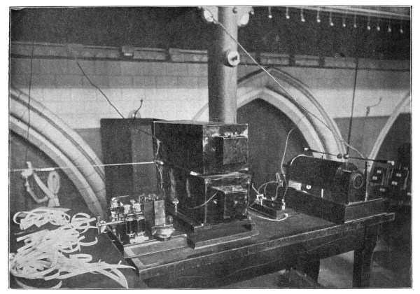
Fig. 51 (p. 761, The Electrician, Vol. XLIII.).—
Apparatus for Sending and Receiving, shown by Prof. Fleming to the British Association at Dover.
A diagram of Marconi’s connection of sensitive tube to the relay and tapper-back and Morse instrument, where W represents the elevated wire, is given in Fig. 52.
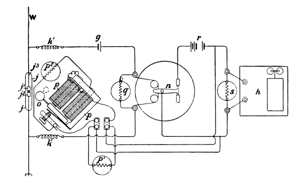
Fig. 52 (Fig. 2, of p. 691, The Electrician, Vol. XLII.).—
Diagram of the connection of Relay and Tapper-back and Morse Instrument, as given in Mr. Marconi’s Paper in the Journal of the Inst. Elec. Engineers for April, 1899; the relay being an ordinary Siemens polarised relay.
The mast at the South Foreland was stated to be 150 ft. high, but the cliff on which it stands must be at a still greater elevation above the sea. It was from this station that the real distant signalling was performed, and probably not from the lower mast at Dover.