ELECTRICAL LABORATORY FOR BEGINNERS.
Reading edition
By GEO. M. HOPKINS.
It is only when theory and practice, study and experiment, go hand in hand that any true progress is made in the sciences. A head full of theory is of little value without practice, and although the student may apply himself with all his energies for years, his time will, to a great extent, have been spent in vain, unless he by experiment rivets the ideas he gains by his study.
In the study of electricity, for example, let the student try to remember the position a magnetic needle will take when placed below or above a conductor carrying a current which flows in a known direction. Without experiment there are nine chances of forgetting to one of remembering; but let the student try the experiment, and he will ever afterward be able to determine the direction in which the current is flowing by the position taken by the needle relative to the conductor.
In the matter of ampere turns, as another example, it is quite simple to assert that a ten ampere current carried once around a soft iron bar produces the same result as a one ampere current carried ten times around the bar, but how much more strongly is this fact stamped upon the memory when its truth is established by experiment?
Reading about a fact, or commiting to memory the literature of a subject, is desirable and even necessary, but knowledge of this character partakes more of the nature of faith than that gained by actual experience.
Let the reader learn first all that can be learned by the aid of this simple apparatus, then branch out to allied things, making each step as thorough as possible, and before long he will be congratulating himself on having gained at least an elementary knowledge of electricity.
Very little can be done in the way of electrical experiment without an electrical generator of some sort, and nothing at present known can excel a battery for this purpose. Although not the most desirable battery for all purposes, that shown in Fig. 1 is the most desirable for the amateur who desires a strong current for a short time. It is formed of two plates, a, of carbon arranged on opposite sides of an amalgamated plate, b, of zinc, and separated from the zinc by strips of wood. Bars of wood are placed outside of the carbon plates, and the four bars are fastened together by two common wood screws, thus clamping all the bars and the zinc and carbon plates securely in the position of use.
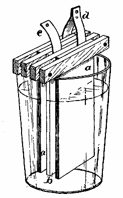
FIG. 1.—SIMPLE BATTERY.
Between the zinc plate and the wooden bar adjoining it is inserted a strip of copper, c, for leading away the current from the zinc pole of the battery, and between the carbon plates and the wooden bars is inserted a doubled strip of copper, d, forming a connection between the two carbon plates, and at the same time serving as a conductor for conveying away the current from the carbon pole of the battery. This element is to be plunged into a tumbler of sufficient depth to allow the wooden bars to rest on the upper edge of the tumbler, while the lower ends of the plates are one-half or three-quarters inch above the tumbler bottom.
THE SOLUTION.
In the tumbler is placed a solution consisting of two-thirds of a tumblerful of water, two ounces of bichromate of potash, and two ounces of sulphuric acid. The bichromate of potash should be dissolved first, then the acid should be slowly and carefully added. As the solution heats, it is well to prepare it in an earthen vessel, which is not liable to break. These materials should be used with great caution, as they are poisonous, and the solution is very corrosive, destroying almost everything with which it comes in contact. With proper care, however, there is no danger in using the solution. It gives off no poisonous vapors. Of course it is advisable to make the solution in quantities of a gallon or so when convenient.
The battery compound known as the C and C battery compound, sold in tin cans at most electric stores, is very convenient. It is only necessary to place two or three ounces of it in the tumbler and add the amount of water above mentioned, stirring the solution with a glass or rubber rod until the crystals are dissolved.
A caution is necessary here. If only a portion of the contents of the can are to be dissolved, it will be necessary to place the remainder in a glass or earthen jar, as it will absorb moisture and rapidly eat its way through the can.
The zinc plates should be amalgamated by plunging them into the bichromate solution, then sprinkling on a minute quantity of mercury, rubbing it about by means of a swab, until the entire exposed surface is covered with mercury.
CONVENTIONAL SIGN FOR THE BATTERY AND GALVANOMETER.
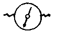
In making electrical diagrams it is necessary to frequently represent a battery. It requires too much time to make a sketch or drawing of a battery. Besides this, the drawing of any particular kind of battery might be misleading. A sign representing the galvanic battery has been universally adopted. It consists of a long, thin mark or dash, representing the carbon electrode, and a shorter, thick mark representing the zinc electrode, thus: Where more cells are required, this sign is repeated once for each cell, thus: The galvanometer is represented thus:


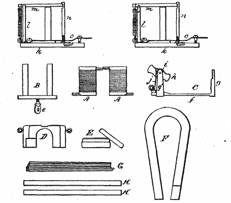
By the use of the battery and a few articles such as may be found anywhere, in addition to the pieces shown in Fig. 2, all the experiments here described may be performed. As these pieces are shown half size in the diagrams, Fig. 2, and about full size in the perspective views, it will be unnecessary to give dimensions. The bobbins, A A, are wound with No. 24 double cotton-covered magnet wire, the terminals being soldered to eyes formed of pieces of spring wire bent so as to form helical coils of two turns each, with the ends inserted in holes drilled in heads of the spools. These coiled wires answer a good purpose in making electrical connections. The magnet frame, B, consisting of the cores and the yoke formed integrally of a single soft gray iron casting, is adapted to receive the bobbins, A A, to form an electro-magnet. The yoke of the magnet is provided with a thumb-screw, e, for securing the magnet to the motor frame, C. The latter is furnished with a base piece, f, a slotted standard for receiving the clamping screw, e, of the magnet, and the standards, g, in which is journaled the armature, h, on a wire extending through both the standards and the armature.
The armature, h, consists of an oblong rectangular soft iron frame having at one end a small pulley and at the other end an elliptical boss, i, which is arranged obliquely to form in conjunction with the spring, j, a circuit closer and opener, which closes the circuit twice during each revolution of the armature, just as one of its side bars is approaching the poles of the magnet and breaks it as the bar comes opposite the poles of the magnet.
The spring, j, is bent into a loop and its lower end is inserted in a wooden plug driven into a hole in the base piece, f.
In the upper part of Fig. 2 are shown two telegraph instruments less the bobbins. Each instrument (Fig. 14) consists of a wooden base, k, a right angled soft iron bar, l, having the central part of its upper end brought to an obtuse angle, an armature, m, fitted loosely to the angled end of the bar, a notched brass standard, n, for limiting the movement of the armature, a retractile spring for lifting the armature, a spring key, o, pivotally secured to the base by a common wood screw, and a contact point projecting from the base under the key.
Besides these there is a D shaped block, to answer as a frame to the galvanometer, a common pocket compass, E, fitted to a circular cavity in the top of the block, D, a permanent U magnet, F, a bundle of soft iron wires, G, and two copper strips, H.
DECOMPOSITION OF WATER.
To illustrate the decomposition of water, connect the copper strips, H H, to the poles of the battery by means of wires, as shown in Fig. 3, and insert them in a tumbler of water acidulated with a few drops of sulphuric acid. Instantly bubbles will rise from the copper strips, showing that gas is being disengaged from the water. The strip connected with the carbon plate will disengage oxygen, while the strip connected with the zinc plate will disengage hydrogen.
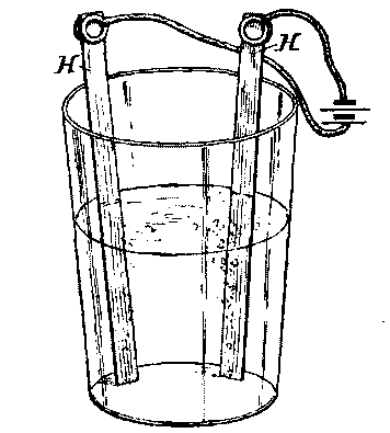
FIG. 3.—DECOMPOSITION OF WATER.
SOLENOID.
By connecting one of the coils, A, with the battery by means of the wires, the action of a helix or solenoid is shown. When so connected, the helix will draw up with itself a barrel pen, or any light iron or steel object. (See Fig. 4.) This is not a true solenoid, but it is generally known by that name. In a true solenoid one of the terminals is passed back through the center of the coil.
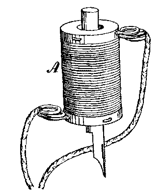
FIG. 4.—SOLENOID.
MAGNETIZATION OF STEEL.
By inserting in the solenoid a knitting needle, or any bar of hardened or tempered steel, and sending a current through the coil, the steel will become permanently magnetized.
ELECTROMAGNET.
By placing the two coils, A, upon the magnet frame, B, and connecting one terminal of each with the battery, the remaining terminals being connected together, as shown in Fig. 5, an electromagnet is formed which will lift several pounds.
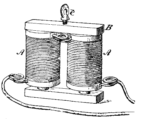
FIG. 5.—ELECTROMAGNET.
ELECTRIC MOTOR.
By placing the magnet thus formed upon the motor base, C, in front of the armature, h, as shown in Fig. 6, and connecting one terminal of the magnet with the battery and the other with the clamping screw, e, of the magnet, and by connecting the commutator spring, j, with the remaining pole of the battery, the motor will be made to rotate rapidly.
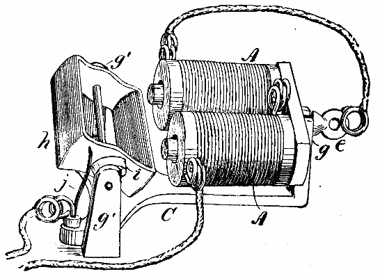
FIG. 6.—MOTOR.
COMPASS AND MAGNETIC EXPERIMENTS.
By placing one end of the bar magnetized by the solenoid near the compass contained by the cabinet (Fig. 7) it will be seen that one end of the compass needle is attracted. When the opposite end of the bar is presented to the same end of the needle, that end of the needle will be repelled and the opposite one attracted, showing that like poles repel each other while unlike poles attract.
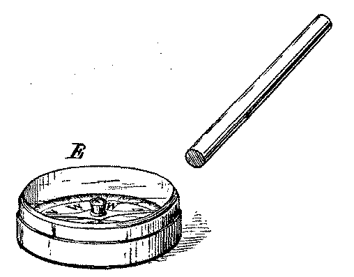
FIG. 7.—MAGNETIC EXPERIMENT.
GALVANOMETER.
By placing one of the coils, A, in the block, D, then placing in the cavity in the top of the block the compass, with the line marked N S arranged at right angles to the axis of the coil, a serviceable galvanometer will be formed (Fig. 8). By turning the galvanometer so that the needle will point north and south without the current passing, with N underneath one end of the needle, and then connecting the poles of the battery with the terminals of this galvanometer, a deflection of the compass needle will be produced, the direction of which depends upon the direction of the current.
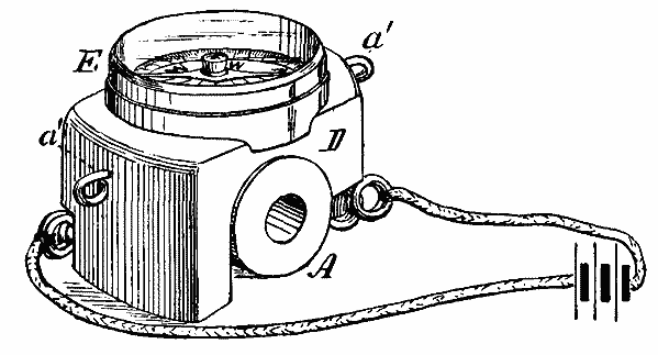
FIG. 8.—GALVANOMETER.
EXPERIMENTS SHOWING THE EFFECTS OF RESISTANCE.
By placing the galvanometer in the circuit of the battery, as shown in Fig. 9, and noting the deflection of the needle, it will be ascertained that a certain amount of current is flowing. Now, by placing in the circuit, in addition to the galvanometer, the remaining coil of the magnet, thus introducing considerable resistance, the current will be diminished, as shown by a smaller deflection of the needle.
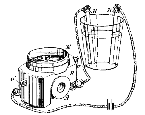
FIG. 9.—EFFECT OF RESISTANCE.
RESISTANCE OF A FLUID CHANGED BY THE ADDITION OF ANOTHER FLUID.
A very pretty and instructive experiment may be performed by arranging the apparatus as shown in Fig. 10, with the copper strips, H H, inserted in clean water and the galvanometer placed in the circuit. The deflection of the galvanometer needle will be very slight, showing that the resistance of clean water is considerable. A few drops of sulphuric acid or even vinegar will increase the conductivity of the water so as to produce a marked deflection of the galvanometer needle.
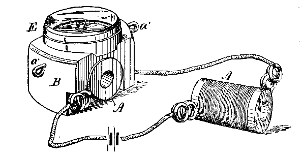
FIG. 10.—RESISTANCE OF FLUIDS.
Common salt added to the water will produce the same effect.
MAGNETIC ELECTRIC INDUCTION.
By placing one of the coils, A, on the magnet frame, B, and connecting it by the wires with the galvanometer, arranged as before described, and bringing the permanent magnet, F, suddenly against the poles of the magnet, as shown in Fig. 11, a current will be induced in the coil, which, in passing through the galvanometer, causes the needle to be deflected in one direction, and when the permanent magnet is suddenly removed from the electro-magnet, a current will be set up in the opposite direction, which will cause a deflection of the needle of the galvanometer in the opposite direction.
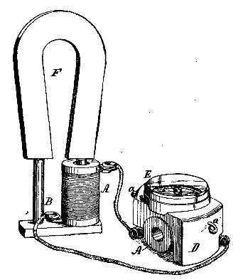
FIG. 11.—MAGNETO-ELECTRIC INDUCTION.
INDUCTION COIL.
By placing both coils, A, upon the bundle of soft iron wires, G, connecting one of them with the terminals of the battery, as shown in Fig. 12, and holding the terminals of the other coil in the moistened thumb and fingers of the two hands, when the battery circuit is opened and closed by touching one of the wires to the battery, and removing it, a slight shock will be felt from the coil which is disconnected from the battery. By placing a coarse file in the circuit and drawing one of the terminals along the file the circuit will be rapidly interrupted. This shock is due to the current induced in the detached coil by the magnetism of the bundle of wires.
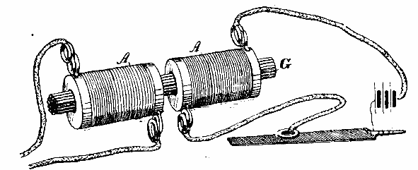
FIG. 12.—INDUCTION COIL.
EXTRA CURRENT.
An experiment showing the extra or self-induced current consists in arranging the motor as shown in Fig. 6, and connecting wire with each conductor leading from the battery to the motor, as shown in Fig. 13. If these wires are grasped one in each hand while the motors is in motion, a slight shock will be felt, providing the hands are moistened.
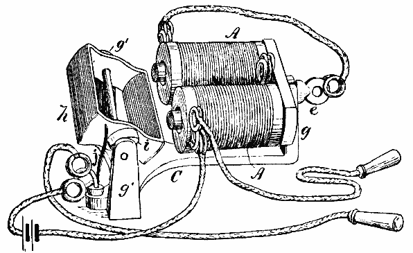
FIG. 13.—EXTRA CURRENT.
TELEGRAPH SOUNDERS AND KEYS.
The cabinet contains material for two telegraph sounders and keys which will enable the user to establish a short telegraph line with a single cell of battery. The armature, m, may be lifted from its pivot so as to permit of slipping one of the coils, A, on to the round magnetic core of the sounder. The armature is then replaced, as shown in Fig. 14, and the small retractile spring at the rear of the instrument is arranged to draw down the shorter arm of the armature lever. One of the terminals of the coil, A, is connected with the turned up pivoted end of the telegraph key, o, on the same base. The other terminal is connected with one pole of the battery and the contact point of the key is connected with the other pole of the battery, as shown. By swinging the key laterally, so as to remove it from the contact point, it will be found that every touch of the key produces a movement of the sounder lever. To connect the two instruments together upon a line, it is only necessary to connect the two keys with one wire and the terminals of the two coils with another wire, cutting one of these wires and inserting the battery.
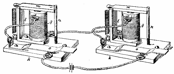
FIG. 14.—TELEGRAPH KEYS AND SOUNDER.
As soon as the operator ceases to work his instrument he should place the key in contact with the contact point, and cause it to remain there by slipping the end of the key under the head of the screw provided for that purpose. The other operator can then proceed to send his message.
Those who desire to practice telegraphy should learn the Morse telegraphic code.
MAGNETIC FIGURES.
By arranging the coil so as to form an electro-magnet, as before described, and holding the magnet under a plate of glass sprinkled with fine iron filings, as shown in Fig. 15, and then sending a current through the magnet, at the same time jarring the glass by striking it with a lead pencil, a magnetic figure will be formed which is sometimes called the magnetic spectrum. By connecting the terminals of the coils diagonally with each other, and connecting the remaining terminals with the battery, two like poles will be formed, and the magnetic figures will have an entirely different appearance, owing to the repulsion between the two like polarities. Different figures may be produced by using the solenoids without the iron cores.
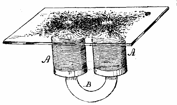
FIG. 15.—MAGNETIC FIGURES.
EXPERIMENT SHOWING THE CURRENT.
By removing the coil, A, from beneath the compass, E, and connecting the ends of the transverse wire, a' a', with the battery Fig. 16, then lifting the plates of the battery out of the solution and allowing the needle to come to rest, it will be found upon inserting the plates of the battery in the solution, very gradually, that the deflection of the needle will increase with the increase of plate surface submitted to the action of the battery fluid; and if, when the greatest deflection is reached, the coils or solenoids are introduced into the circuit, one after the other, it, will be found that each added coil diminishes the current, as will be shown by the diminished deflection of the needle.
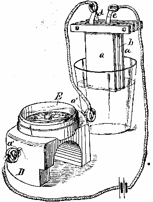
FIG. 16.—EXPERIMENT SHOWING THE CURRENT.
MICROPHONE AND TELEPHONE.
Take two small carbon rods, p p, if procurable, if not, use two ordinary nails, and connect them up in the circuit of the battery; lay them upon a thin box so that the rods or nails cross each other, as in Fig. 17; insert the electromagnet in the circuit; move the coils out a little beyond the ends of the cores, lay a thin iron plate over the ends of the coils, then jar the box upon which the bars, p p, are laid, or drop a pin upon it, or scratch it with a piece of paper, and the sound will be heard by placing the ear against the iron plate resting upon the coils of the magnet.
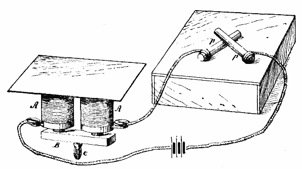
FIG. 17.—MICROPHONE AND TELEPHONE.
ELECTRO METALLURGY.
Dissolve an ounce of sulphate of copper in a half pint of water; add a few drops of sulphuric acid; connect with the zinc pole of the battery the object to be coppered. To the wire connected with the carbon attach a small plate of copper. Hang the object and the copper plate in the solution a short distance apart. A deposit of copper will be quickly formed.
THE HEATING EFFECT OF THE CURRENT.
With a piece of very fine platinum wire (No. 36 or 40), placed in the circuit of the battery, the heating effect of the current may be shown. A half inch of No. 36 platinum wire will serve for the experiment. If the battery is in good condition it will heat from 1/8 to 1/4 inch of the wire red hot. This is sufficient to light gas or an alcohol lamp, also to ignite powder or gun cotton.
A short piece of a watch hair spring, or a piece of very fine iron wire, if placed in the circuit will be made very hot.
DUPLICATION OF BATTERIES.
Should the experimenter desire to go more deeply into the effects of the current, he will need a more powerful battery. The battery described has been made on a very simple plan, to enable the amateur to copy it without difficulty or great expense. There is no mystery about the battery. Any one can make it. All that is required is a plate of zinc, two plates of carbon, some strips of wood and copper, and two common wood screws for each cell. The tumblers may be had anywhere.
Although it is advisable to use insulated wire for making the electrical connections, bare wires may be used if care is taken in arranging them, so that they will not touch each other or other metallic objects which would complete the circuit.
It will be found convenient if the elements of the battery are arranged upon a frame of some sort, by means of which they may be raised or lowered all together, and supported at any desired height.