MANUFACTURE OF PHOTOGRAPHIC SENSITIVE PLATES.
Reading edition
Quite recently Messrs. Marion & Company, London, began on their own account to manufacture sensitive photographic plates by machinery, and the operations are exceedingly delicate, for a single minute air bubble or speck of dust on a plate may mar the perfection of a picture. Their works for the purpose at Southgate were erected in the summer of 1886, and were designed throughout by Mr. Alexander Cowan.
Fig. 1.
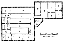
Buildings of this kind have to be specially constructed, because some of the operations have to be carried on in the absence of daylight, and in that kind of non-actinic illumination which does not act upon the particular description of sensitive photographic compound manipulated. Glass and other materials have therefore to pass from light to dark rooms through double doors or double sliding cupboards made for the purpose, and the workshops have to be so placed in relation to each other that the amount of lifting and the distance of carriage of material shall be reduced to a minimum. Moreover, the final drying of sensitive photographic plates takes place in absolute darkness. Fig. 1 is a ground plan of the chief portion of the works. In this cut, A is the manager's private office, B the counting house, C the manager's laboratory, and D his dark room for private experiment, which can thus be conducted without interfering with the regular work of the establishment. E is the carpenter's shop and packing room, F the albumen preparation room, G the engine room, with its two doors; the position of the engine is marked at H. The main building is entered through the door, K; the passage, L, is used for the storage of glass, and has openings in the wall on one side to permit the passage of glass into the cleaning room, M; this room is illuminated by daylight. The plates, after being cleaned, pass into the coating rooms, N and O, into which daylight is never admitted; the coating machine is in the room, N, and three hand coating tables in the room, O; both these rooms are illuminated by non-actinic light.
Fig. 2.
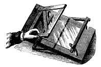
Fig. 3.
The walls of N and O are of brick, to keep these interior rooms as cool as possible in hot weather, for the making of photographic plates is more difficult in summer time, because the high temperature tends to prevent the rapid setting of the gelatine emulsion upon them. At the end of these rooms and communicating with both is the lift, P, by which the coated plates are carried to the drying rooms above, which there cover the entire area of the main building; they consist of two rooms measuring 60 ft. by 30 ft., and are each 30 ft. high at the highest part in the center of the building; these rooms are necessarily kept in absolute darkness, except while the plates are being stored therein or removed therefrom, and on such occasions non-actinic light is used. After the plates are dry, they come down the lift, Q, into the cutting and packing room, R, which is illuminated by non-actinic light. In the drying rooms the batches of plates are placed one after the other on tram lines at one end of the room, and are gradually pushed to the other end of the building, so that the first batches coated are the first to be ready to be taken off when dry, and to be sent down the lift, Q. The plates in R, when sufficiently packed to be safe from the action of daylight, are passed through specially constructed openings into the outside packing room, S, where they are labeled. The chemicals are kept in the room, T, where they are weighed and measured ready for the making of the photographic emulsion in the room, U. The next room, V, is for washing small experimental batches of emulsion, and W is the large washing room. The emulsion is then taken into the passage, X, communicating with the two coating rooms. A centrifugal machine in the room, Y, is used for extracting silver residues from waste materials, also for freeing the emulsion from all soluble salts. Washing and cleaning in general go on in the room, Z.
Fig. 4.—PLATE-WARMING MACHINE.
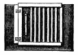
The glass for machine coating is cut to standard sizes at the starting, instead of being coated in large sheets and cut afterward—a practice somewhat common in this industry. The disadvantage of the ordinary plan is that minute fragments of glass are liable to settle upon the sensitive film and to cause spots and scratches during the packing operations; any defect of this kind renders a plate worthless to the photographer. When any breakages take place in the cutting, it is best that they should occur at the outset, and not after the plate has been coated with emulsion. The cutting when necessary is effected by the aid of a "cutting board," Fig. 2, invented by Mr. Cowan, and now largely in use in the photographic world. This appliance is used to divide into two equal parts, with absolute exactness, any plate within its capacity, and it is especially useful in dimly lighted rooms. It consists of four rods pivoted together at the corners and swinging on two centers, so that in the first position it is truly square, and in other positions of rhomboid form, the two outer bars approaching each other like those of a parallel ruler. The hinge flap comes down on the exact center of the plate, minus the thickness of the block holding the diamond. By this appliance plates can be cut in either direction. Fig. 3 represents a similar arrangement for cutting a number of very small plates out of one large one; in this the hinge flap is made in the form of a gridiron, and the bars are spaced at accurate distances, according to the size of the plate to be cut, so that a plate 10 in. square, receiving four cuts in each direction, will be divided into twenty-five small plates.
Fig. 5.
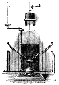
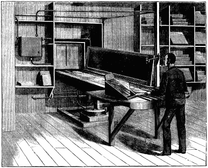
Before being cleaned all sharp edges are roughly taken off those plates intended for machine coating by girls, who rub the edges and corners of the plates upon a stone; the plates are then cleaned by any suitable method in use among photographers. The plates, now ready for the coating room, have to be warmed to the temperature of the emulsion, say from 80 deg. F. to 100 deg. F., before they pass to the coating machine, the inventor of which, Mr. Cadett, having come to the conclusion that, if the plates are not of the proper temperature, the coating given will be uneven over various parts of the surface. The plate-warming machine is represented in Fig. 4; it was designed by Mr. A. Cowan, and made by his son, Mr. A. R. Cowan. It consists of a trough 7 ft. long by 3 in. deep, forming a flat tank, through which hot water passes by means of the circulating system shown in the engraving. To facilitate the traveling of the glass plates without friction the top of the tank is a sheet of plate glass bedded on a sand bath. An assistant at one end places the glasses one after the other on the warm glass slab, and by means of a movable slide pushes them one at a time under the cover, which cover is represented raised in the engraving to show the interior of the machine. After having put one glass plate on the slide, another cannot be added until the man in the dark room at the other end of the slide has taken off the farthest warmed plate, because the slide has a reciprocating movement. This heating apparatus is built at right angles to the coating machine in the next room, in order to be conveniently placed in the present building; but it is intended in future to use it as a part of the coating machine itself, and to drive it at the same speed and with the same gearing, so that the cold plates will be put on by hand at one end, get warmed as they pass into the dark room, at the other end of which they will be delivered by the machine in coated condition. Underneath the heating table is a copper boiler, with its Bunsen's burner of three concentric rings to get up the temperature quickly and to give the power of keeping the water under the heating slab at a definite temperature, as indicated by a thermometer. The cold water tank of the system is represented against the wall in the cut.
Fig. 6.
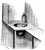
Fig. 5 represents the hot water circulating system outside the coating rooms for keeping the gelatine emulsions in these dimly lighted regions at a given temperature, without liberating the products of combustion where the emulsion is manipulated. The temperature is regulated automatically. It will be noticed where the pipes enter the two coating rooms, and Fig. 6 shows the copper inside one of them heated by the apparatus just described. The emulsion vessel in the copper is surrounded by warm water, and the copper itself is jacketed and connected with the hot water pipes, so forming part of the circulating system.
Fig. 7.—GENERAL VIEW OF COATING MACHINE.
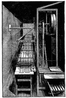
Fig. 7 is a general view of the coating machine recently invented by Mr. Cadett, of the Greville Works, Ashtead, Surrey. The plates warmed in the light room, as already described, are delivered near the end of the coating table, where they are picked off a gridiron-like platform, represented on the right hand side of the cut, and are placed by an assistant one by one upon the parallel gauges shown at the beginning of the machine proper; they are then carried on endless cords under the coating trough described farther on. After they have been coated they are carried onward upon a series of four broad endless bands of absorbent cotton—Turkish toweling answers well—and this cotton is kept constantly soaked with cold water, which flows over sheets of accurately leveled plate glass below and in contact with the toweling; the backs of the plates being thus kept in contact with fresh cold water, the emulsion upon them is soon cooled down and is firmly set by the time the plates have reached the end of the series of four wet tables. They are then received upon one over which dry toweling travels, which absorbs most of the moisture which may be clinging to the backs of the plates; very little wet comes off the backs, so that during a day's work it is not necessary to adopt special means to redry this last endless band. What are technically known as "whole plates," which are 8½ in. by 6½ in., are placed touching each other end to end as they enter the machine, and they travel through it at the rate of 720 per hour; smaller sizes are coated in proportion, the smaller the plates the larger is the number coated in a given time. The smaller plates pass through the machine in two parallel rows, instead of in a single row, so that quarter plates, 4¼ in. by 3¼ in., are delivered at the end of the machine at the rate of 2,800 per hour, keeping two attendants well employed in picking them up and placing them in racks as quickly as they can do the work. The double row of cords for carrying two lines of small plates through the machine is represented in the engraving. Although the plates touch each other at their edges on entering the machine, they are separated from each other by short intervals after being coated; this is effected by differential gearing. The water flowing over the tables for cooling the plates is caught in receptacles below and carried away by pipes. Between each of the tables is a little roller to enable small plates to travel without tilting over the necessary gap between each pair of bands.
Fig. 8.
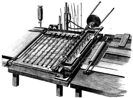
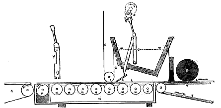
The feeding trough of Cadett's machine is represented in Fig. 8. The plates, cleaned as already described, are carried upon the cords under a brass roller, the weight of which causes sufficient friction to keep the plates from tilting; they next pass under a soft camel's hair brush to remove anything in the shape of dust or grit, and are then coated. They afterward pass over a series of accurately leveled wheels running in a tank of water kept exact by an automatic regulator at a temperature of from 80 deg. Fah. to 100 deg. Fah., by means of a small hot water circulating system. The emulsion trough is jacketed with hot water at a constant temperature. This trough is silver plated inside, because most metals in common use would spoil the emulsion by chemical action. The trough is 16 in. long; it somewhat tapers toward the bottom, and contains a series of silver pumps shown in the cut; the whole of this series of pumps is connected with one long adjustable crank when plates of the largest size have to be coated; when coating plates of smaller sizes some of the pumps are detached. A chief object of the machine is to deliver a carefully measured quantity of emulsion upon each plate, and this is done by means of pumps, in order that the quantity of emulsion delivered shall not be affected by changes in the level of the emulsion in the trough; the quantity delivered is thus independent of variations due to gravity or to the speed of the machine. These pumps draw the emulsion from a sufficient depth in the trough to avoid danger from the presence of air bubbles, and the bottom of the trough is so shaped that should by chance any sedimentary matter be present, it has a tendency to travel downward, away from the bottoms of the pumps. There is a steady flow of emulsion from the pumps to the delivery pipes, then it passes down a guide plate of the exact width of the plate to be coated. Immediately in front of the guide plate is a fixed silver cylinder, kept out of contact with the plate by the thickness of a piece of fine and very hard hempen cord, which can be renewed from time to time. These cords keep the cylinder from scraping the emulsion off the plate, and they help to distribute it in an even layer. There would be two lines upon each plate where it is touched by the cords, were not the emulsion so fluid as to flow over the cut-like lines made and close them up.
Fig. 9.
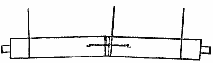
The silver cylinder to a certain extent overcomes the effects of irregularities in the glass plates, for the cylinder is jointed somewhat in the cup and ball fashion, and is made in two or more parts, which parts are held together by lengths of India rubber.
Fig. 10.
The arrangement is shown in section in Fig. 9, in which A is the hot water jacket of the emulsion vessel; B, the crank driving the pumps; C, a pump with piston in position; D, delivery tube of the pump; E, the silver guide plate to conduct the emulsion down to the glass; F, the spreading cylinder; G, the cords regulating the distance of the cylinder from the glass plates; H, soft camel's hair brush; K, friction roller; L L L, three plates passing under the emulsion tank; M, knife edged wheels in the hot water tank, N; the "plucking roller," P, has a hot water tank of its own, and travels at slightly greater speed than the other rollers; R is the beginning of the cooling bands; T, the driving cords; and W, a level of the emulsion in the trough. Y represents one of the bucket pistons of the pumps, detached. The construction of the crank itself is such that, by adjustment of the connecting rods, more or less emulsion may be put upon the plates. Mr. Cowan, however, intends to adjust the pumps once for all, and to regulate the amount of emulsion delivered upon the plates by means of driving wheels of different diameters upon the cranks.
Fig. 10 is a section of the hollow spreading cylinder, made of sheet silver as thin as paper, so that its weight is light. For coating large plates it is divided in the center, so as to adapt itself somewhat to irregularities in the surface of each plate. In this case it is supported by a third and central thread, as represented in the cut. Otherwise the cylinder would touch the center of the plate. Its two halves are held together by a slip of India rubber.—The Engineer.