Chapter IX · THE STRENGTH OF A SCAFFOLD
Reading edition
The strength of a scaffold equals the resistance that its members and their connections can offer to the strains that act upon it. The timbers used may fail in various ways.
First.—As beams, they may fail to resist a cross strain.
Secondly.—As pillars and struts, they may fail to resist compression in the direction of their length.
Thirdly.—As ties and braces, they may fail to resist tension; that is, a strain tending to pull a beam asunder by stretching.
The loads that act upon a scaffold may be dead, that is to say, they do not create a shock; or live, which means they are not stationary, and may cause shock and vibration.
A live load causes nearly double the strain that a dead load produces. If, therefore, both are of equal weight, the timber under strain will carry as a live load only one half of what it would carry as a dead load. The breaking weight is the load that will cause fracture in the material. The safe load is the greatest weight that should be allowed in practice. It is in proportion to the breaking load, and that proportion is termed the factor of safety.
Experiments have been made to determine the resistance of timber to fracture under the various forces that act upon it.
The result of these experiments is expressed by a given number, termed a constant, which varies with the different growths of timber and the different strains to which they are subjected.
The constants (C) for the strength of different kinds of timber under a cross strain are as follows:
Table I.
Material C in lbs. for rectangular beams supported at both ends Authority
Spruce 403
Larch 392
Fir, Northern
Fir, Dantzic 448
Fir, Memel
Fir, Riga 392 Hurst
Elm 336
Birch 448
Ash, English 672
Oak, English 560
Oak, Baltic 481
The factor of safety for beams under a cross strain is one-fifth.
Table II.—Constants (D) for compression.
Wet Dry
Spruce 6,499 to 6,819 Spruce —
Larch (fallen two months) 3,201 to 5,568 Larch 1,645
Fir (white deal) 6,781 to 7,293 Fir, Riga 2,035
Fir, Memel 2,361
Elm 10,331 Elm 1,620
Birch, English 3,297 to 6,402 Birch —
Birch, American 11,663
Ash 8,683 to 9,363 Ash 1,840
Oak, English 6,484 to 10,058 Oak, English 2,068
Oak, Dantzic (very dry) 7,731 Oak, Dantzic 2,410
Pillars of medium length—the constant for bending is taken at 2·9 for all timbers.
The working load on pillars should not be greater than one-tenth of the breaking weight; but if the pillars are used for temporary purposes, and are over 15 and under 30 diameters one-eighth, and under 15 diameters one-fifth may be taken as the factor of safety.
Table III.—The Constants (E) for Breaking Weight under tensional stress.
Material E in lbs. per unit of 1 sq. inch Authority
Spruce 3,360
Larch 3,360
Fir 3,360 Hurst
Elm 4,480
Ash 4,480
Oak 6,720
The working load should not exceed one-fifth of the weight that would cause rupture.
Beams subject to a Transverse Strain.—The loads that act upon a beam may be concentrated, that is, acting at one point, or distributed, which means that the load is evenly placed over the entire length of the beam or a portion of the beam.
An evenly distributed load is considered to act at a point immediately below its centre of gravity.
If a beam carries several loads they are considered to act at a point immediately below the resultant centre of gravity of the whole.
Beams may be fixed, loose, or continuous. When fixed they are built into the structure; if loose they are supported only; and are continuous when they have more than two points of support in their length.
For practical purposes, a continuous beam may be considered one-half stronger than when supported at two points only.
The strength of a solid rectangular beam varies directly as its breadth, the square of its depth, and inversely as its length.
The formula for finding the breaking weight (B.W.) of a solid rectangular beam supported at each end and loaded at its centre is as follows:
B.W. = (bd2)/l × c
where b = breadth in inches; d2 = depth multiplied by itself in inches; l = length of beam between supports in feet; c = the constant found by experiment on the timber in use.
Example.—Find the B.W. of a solid rectangular beam of Northern fir, 9 in. by 9 in., and 10 feet between supports, loaded at its centre.
The constant for Northern fir (Table I.) is 448.
B.W. = (9 × 92)/10 × 448 = (9 × 9 x 9 x 448)/10 = 14 tons 11 cwt. 2 qrs. 111⁄5 lbs.
One-fifth of this must be taken as a safe load, say 2 tons 18 cwt.
The strength of a solid cylindrical beam varies directly as its diameter cubed, and inversely as its length.
The formula for finding the breaking weight (B.W.) of a solid cylindrical beam supported at each end and loaded at its centre is as follows:
B.W. = d3/l × c × 10/17
where d3 = least diameter in inches cubed; l = length of beam between supports in feet; c = the constant found by experiment on rectangular beams; 10/17 = the proportion that cylindrical beams bear to square beams,
Example.—Find the B.W. of a solid cylindrical beam of spruce fir 6 inches in diameter and 4 feet between supports.
The constant C for spruce fir is (Table I.) 403.
B.W. = (6 × 6 × 6 × 403 × 10)/(4 × 17) = 12,8013⁄17 lbs. = 5 tons 14 cwt. 1 qr. 53⁄17 lbs.
One-fifth of this must be taken as a safe load, say 1 ton 2 cwt. 3 qrs.
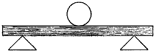
Fig. 132
The above diagram (fig. 132) illustrates the supports and loading of the beams just considered. The following diagrams show beams variously supported and loaded, and their relative strength to the first. By adding to the formulæ already given, the proportion that these following bear to the first, the same formulæ can be used for all.
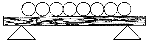
Fig. 133
Beam supported at both ends and load equally distributed bears double of fig. 132.
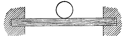
Fig. 134
Beam fixed, load in centre, bears half more than fig. 132.
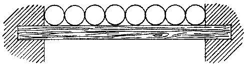
Fig. 135
Beam fixed, load evenly distributed, bears triple of fig. 132.
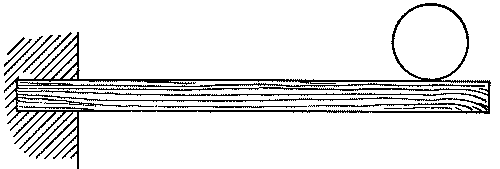
Fig. 136
Beam fixed one end only, load on free end, bears a quarter of fig. 132.
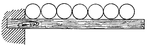
Fig. 137
Beam fixed one end only, load evenly distributed, bears half of fig. 132.
To find the effective length of a beam supported at both ends when the position of the load is varied:
Rule.—Divide four times the product of the distances of the load from both supports by the whole span, in feet.
Example.—Find the effective length of a beam the supports of which are 6 feet apart, the load acting at a point 1 foot from its centre.
The distances of the load from each support in this case are 2 feet and 4 feet.
Therefore (2 × 4 × 4)/6 = 51⁄3 feet, effective length of beam.
Posts and Struts subject to Compression.5—Posts and struts, when above 30 diameters in length, tend to fail by bending and subsequent cross breaking. When below 30 and above 5 diameters in length, their weakness may partly be in their bending and partly by crushing, and when below 5 diameters in length by crushing alone; but, as these latter are rarely met with in scaffolding, they need not be considered.
On the resistance of long posts.—To find the greatest weight, W, that a square post of 30 diameters and upwards will carry:
Multiply the fourth power of the side of the post in inches by the value of D (Table II.), and divide by the square of the length in feet. The quotient will be the weight required in pounds.
The formula is as follows:
W = (d4 × D)/L2 = weight in lbs. for square posts to resist bending, where d = depth in inches, D = constant in pounds, for flexure, L = length in feet.
Example.—Find the weight that may be placed upon a post of elm 12 feet long and 4 inches square.
The value of D (Table II.) being 1,620,
(44 × 1,620)/122 = (256 × 1,620)/144 = 2,880 lbs.
One-tenth of this must be taken as a safe working load = 288 lbs.
The strength of cylindrical posts is to square ones as 10 is to 17, the rest of the formula remaining the same, except that d = diameter of post in inches.
When the pillar is rectangular.—Multiply the greater side by the cube of the lesser in inches, and divide by the square of the length in feet. The quotient multiplied by the value of D (Table II.) will give the weight which the post will carry in pounds.
The formula is as follows:
W = (BT3 × D)/L2,
where B = breadth of post in inches; T = least thickness in inches, and the rest of notation as before.
Example.—Find the weight that may be placed on a rectangular post of Dantzic oak 8 in. by 6 in. and 18 feet long.
The value of D (Table II.) being 2,410 lbs.,
(8 × 63 × 2,410)/182 = (8 × 216 × 2,410)/324 = 12,853 lbs.
The safe working load = say, 1,285 lbs.
On the strength of posts of medium length.—When a post is less than 30, but over 5, diameters in length, and therefore tending to fail by crushing as well as by bending, the resistance to crushing is a considerable proportion of the strength. This must, in consequence, be allowed for in any calculation for the breaking weight.
To find the weight that would break a square or rectangular post of between 5 and 30 diameters in length:
Multiply the area of the cross section of the post in square inches by the weight in pounds that would crush a short prism of 1 inch square (Table II.), and divide the product by 1·1 added to the square of the length in feet, divided by 2·9 times the square of the least thickness in inches.
The formula is as follows:
W = DS/(1·1 + L2/T2 2·9) where D = the constant for the resistance to crushing. S = the area of the cross section of the post in square inches. 1·1 is a modification introduced in order that the result may be in accord with the result of experiments. L = the length of the post in feet. T = the least thickness in inches. 2·9 = the constant for the resistance to bending, and which is taken at that figure for all timbers (Table II.).
Example.—Find the breaking weight of a post of Dantzic oak 10 feet long and 6 inches square.
The constant for Dantzic oak (Table II.) is 7,731.
W = (7,731 × 36)/(1·1 + 100/(2·9 × 36)) = 278,316/2·05 = 135,763 lbs.
The factor safety is 1⁄8. Therefore the safe load will be 16,970 lbs.
The strength of cylindrical pillars is to square ones as 10 is to 17.
Braces and Ties subject to a Tensional Strain.—The weight that will produce fracture in a beam strained in the direction of its length, is in proportion to the area of the cross section of the beam multiplied by the weight that would fracture a unit of that area.
The formula is as follows:
B.W. = E S
where E = the cohesive force in lbs. per unit of 1 square inch, as in Table III. S = the sectional area of the beam in square inches.
Example.—Find the B.W. of a rectangular elm brace 9 in. by 3 in. under a tensional strain.
The value of E (Table III.) is 4,480.
B.W. = 4,480 × 9 × 3 = 120,960 lbs.
One-fifth of this should be taken as a safe load,
= 24,192 lbs. = 10 tons 16 cwt.
which is the safe load required.
To find the sectional area of a cylindrical beam square its diameter and multiply by ·7854.
The effect of fracture of a member of a scaffold depends upon its cause and upon the importance of the member destroyed.
If the fracture is caused by a live load, say a heavy stone being suddenly placed over a putlog, it is probable that the suspending rope, if still attached, would prevent more damage being done. If the fracture arose from an increasing dead load, say a stack of bricks being gradually built up by labourers, the mass would probably tear its way through all obstructions. Nevertheless, the entire scaffold, if well braced and strutted, should not come down, the damage remaining local.
The result of fracture of a standard under direct crushing would be somewhat different, as, providing that the scaffold is rigid, the greater strain thrown upon the ledgers, due to the increased distance between supports, would probably cause them to fracture. In this case the damage would probably still remain local. If, owing to the fracture, the effect of the bracing were lost, the whole scaffold would probably fail, as shown in the chapter on Stability.
It should be noted that the ledgers, together with the putlogs when fixed at both ends, apart from carrying the loads, have an important effect upon the standards, as, when securely connected, they divide the uprights into a series of short posts, thus dispelling any likelihood of failing by flexure.