Part 1 — SPECIFICATIONS OF THE National Board of Fire Underwriters FOR THE MANUFACTURE OF STEAM FIRE PUMPS AS RECOMMENDED BY THE National Fire Protection Association.
Reading edition
EDITION OF 1904
THE NATIONAL STANDARD PUMP.
This pump is merely a pump of the well-known “duplex” type, built in a very substantial manner, and with certain improvements suggested by the experience of inspectors with Fire Pumps.
The principal points of difference between the National Standard Pump and the ordinary commercial pump are:
1st. Its steam ports and water passages and air chamber are made much larger than in common trade pumps, so that a larger volume of water can be delivered in an emergency without water hammer.
2nd. It is “rust proofed” that it may start instantly after disuse, by making its piston rods and valve rods of Tobin Bronze, instead of steel; its water pistons, stuffing boxes and rock-shaft bearings of brass, instead of cast iron. Its valve levers are made of steel or wrought-iron forgings, or of steel castings.
3d. The following necessary attachments are all included in the price of the “National Standard Pump,” viz.:—a vacuum chamber, two pressure gauges, a relief valve, a set of brass priming pipes, 2 to 6 hose valves, a stroke gauge, a capacity plate, an oil pump, a sight feed lubricator and a cast-iron relief-valve discharge-cone.
By reason of the larger ports, passageways and pipes, its larger number of valves, and the added attachments, and general superior construction a “National Standard” pump costs more than a common trade fire pump, but the cost per gallon which these pumps can deliver in an emergency by reason of their large passageways, etc., is no greater than for the old style of fire pump and is well worth this extra cost.
Finally it should be remembered that these specifications cover only the outlines of the design, and that all pumps built under them are not of equal merit, for certain of the pump factories possess a broader experience and better shop facilities than others, and that the responsibility for first-class workmanship and strength of materials rests on the pump manufacturers, and not on the insurance companies.
We advise that all contracts call for strict conformity to the National Standard Steam Fire Pump specifications of the National Board of Fire Underwriters.
UNIFORM REQUIREMENTS.
The following specifications for the manufacture of Steam Fire Pumps, developed from those originally drawn by Mr. John R. Freeman, are now used throughout the whole country, having been agreed upon in joint conference by representatives of the different organizations interested in this class of work. They will be known as “The National Standard,” and have been up to this time adopted by the following associations: Associated Factory Mutual Fire Insurance Companies, National Board of Fire Underwriters, National Fire Protection Association.
NATIONAL STANDARD SPECIFICATIONS For the Manufacture of STEAM FIRE PUMPS
1. Workmanship.
a. The general character and accuracy of foundry and machine work must throughout equal that of the best steam-engine practice of the times, as illustrated in commercial engines of similar horse-power.
This refers to strength of details, accuracy of foundry work, accuracy of alignment, accuracy of fits, quality of steam joints and flanges, construction of steam pistons and slide-valves, etc., and does not apply particularly to exterior finish.
2. Duplex Only.
a. Only “Standard Duplex pumps” are acceptable.
So-called “Duplex” pumps consisting of a pair of pumps with “steam-thrown valves” actuated by supplemental pistons are not acceptable.
Experience shows that duplex pumps are more certain of starting after long disuse. The whole power of the main cylinder is available for moving a corroded valve or valve rod, whereas on a single pump with a “steam-thrown” valve no such surplus of power is available.
Further, the direct acting duplex has the great advantage over a fly-wheel pump of not suffering breakage if water gets into steam cylinder.
3. Sizes of Pumps.
a. Only the four different sizes given on the next page will be recognized for “National Standard” pumps.
The multiplicity of odd sizes of “Trade Pumps” is confusing, and different makers have, in the past, estimated the capacity in gallons according to different arbitrary standards.
NATIONAL STANDARD PUMP SIZES.
Pump Sizes. Ratio of Piston Areas. Capacity At 100 lbs. at Pump.
Steam. Water. Stroke. About Number of 11⁄8 in. Streams. Nominal Gals. per Minute. Actual Gals. per Min. as per Art. 4.
14 × 7 × 12 4 to 1 Two 500 4830
14 × 71⁄4 × 12 520
16 × 9 × 12 3 to 1 Three 750 8060
18 × 20 × 12 3 to 1 Four 1000 9990
181⁄2 × 101⁄4 × 12 1050
20 × 12 × 16 23⁄4 to 1 Six 1500 1655
NATIONAL STANDARD PUMP SIZES.(continuation)
Pump Sizes. B Boiler Power Required Full Speed.
Steam. Water. Stroke. Horse Power. Steam Pres. at Pump, lbs. Rev. Per Minute. Piston Travel Feet Per Minute.
14 × 7 × 12 100 40 70 140
14 × 71⁄4 × 12
16 × 9 × 12 115 45 70 140
18 × 20 × 12 150 45 70 140
181⁄2 × 101⁄4 × 12
20 × 12 × 16 200 50 60 160
FOOTNOTE:
b. The above sizes of steam and water cylinders and length of stroke have given general satisfaction and will now be considered as standard.
Often, especially with large pumps, “4 to 1” construction is a mistake, and gives no additional security, although the pump might start and give a few puffs with 30 lbs. of steam on banked fires; because, if any pump of whatever cylinder ratio draws 50 or 100 horse-power of steam from boilers with dead fires, it can run effectively only a very short time (ordinarily, perhaps, 3 to 5 minutes), unless fires are first aroused to make fresh steam to replace that withdrawn.
Steam pressures stated above must be maintained at the pump, to give full speed and 100 lbs. water pressure. Pressure at boilers must be a little more, to allow for loss of steam pressure between boiler and pump. Pumps in poor order, or too tightly packed, will require more steam.
The boiler horse-powers above are reckoned on the A. S. M. E. basis of 341⁄2 lbs. of water evaporated from and at 212 degrees Fahrenheit as the unit of boiler horse-power. From 12 to 15 square feet of water-heating surface in the boiler is commonly assumed necessary for the generation of one horse-power.
Smaller boilers than called for above, if favorably set, and having excellent chimney draft, can sometimes be forced to nearly double their nominal capacity for a short run, as for fire service.
c. 250 gallons per minute is the standard allowance for a good 11⁄8-inch (smooth nozzle) fire stream.
A so-called “Ring Nozzle” discharges only three-fourths as much water as a smooth nozzle of the same bore, and is not recommended.
From fifteen to twenty automatic sprinklers may be reckoned as discharging about the same quantity as a 11⁄8-inch hose stream under the ordinary practical conditions as to pipes supplying sprinkler and hose systems respectively.
4. Capacity.
a. Plunger diameter alone will not tell how many gallons per minute a pump can deliver, and it is not reasonable to continue the old time notion of estimating capacity on the basis of 100 feet per minute piston travel.
b. The capacity of a pump depends on the speed at which it can be run, and the speed depends largely on the arrangement of valves and passageways for water and steam.
c. It is all right to run fire-pumps at the highest speed that is possible without causing violent jar, or hammering within the cylinders. Considerations of wear do not affect the brief periods of fire services or test, hence these speeds are greater than those allowable for constant daily duty.
d. Careful experiments on a large number of pumps of various makes at full speed, show that in a new pump with clean valves, and an air-tight suction pipe, and less than 15 feet lift, the actual delivery is only from 11⁄2 to 5 per cent. less than plunger displacement. This slip will increase with wear, and for a good average pump in practical use, probably 10 per cent. is a fair allowance to cover slip, valve leakage, slight short-stroke, etc.
e. Largely from tests, but partly from “average judgment,” and recognizing that a long stroke pump can run at a higher rate of piston travel in lineal feet per minute than a short stroke pump, and that a small pump can make more strokes per minute than a very large one, the speeds given in the preceding table have been adopted as standards in fire service for direct acting (non-fly-wheel) steam pumps, which have the large steam and water passages herein specified.
f. Rated capacity is to be based on the speed in the preceding table, correcting the plunger displacement for one-half the rod area and deducting 10 per cent. for slip, short-stroke, etc.
Men sometimes ask why, (if they can run a pump smoothly so as to get a delivery of 1,000 gals. per minute,) we should not accept as “a thousand gallon pump,” irrespective of its suction valve area or its exhaust port area or the size of its cylinders.
To this we reply that when new and favorably set almost any pump built according to these specifications can run at a much greater delivery than here rated, but when lift is unusually high or suction pipe long, or when the pump takes its suction under a head, no pump can be run so fast as on, for instance, a 5-foot lift. A solid foundation is also a great and indispensable aid in running a pump fast.
Standard 500-gallon pumps have often delivered 800 gallons, and 1,500-gallon pumps have delivered 2,000 gallons; but some margin must be allowed for unfavorable conditions and for deterioration as a pump grows old, or for the absence of an expert to get its utmost duty.
5. Capacity Plate.
a. Every steam fire-pump must bear a conspicuous statement of its capacity securely attached to the inboard side of air chamber, thus:—
NATIONAL STANDARD FIRE PUMP 16 × 9 × 12 CAPACITY 750 GALLONS PER MINUTE, OR 3 GOOD 11⁄8-IN. SMOOTH NOZZLE FIRE STREAMS FULL SPEED 70 REVOLUTIONS PER MINUTE NEVER LET STEAM GET BELOW 50 POUNDS, NIGHTS, SUNDAYS OR AT ANY OTHER TIME
The name “Underwriter” has been largely used for a considerable time to designate the type of pump covered by the principal features of these specifications. While our preferences are against the use of this word as designating any piece of apparatus objections will not be raised at the present time to its being continued on name plates in place of the words “National Standard,” if manufacturers so desire.
b. This plate must have an area of not less than one square foot, and must be made of an alloy at least two-thirds aluminum and the remainder zinc. The letters must be at least one-half inch in height, plain and distinct, with their surfaces raised on a black background and buffed off to a dead smooth finish.
The name of pump manufacturer may also be placed on this plate, if desired.
c. A smaller plate of composition must be attached to steam chest bearing the size of pump, the shop number, and the name of shop in which the pump was built.
6. Strength of Parts.
a. The maker must warrant each pump built under these specifications to be at time of delivery, in all its parts, strong enough to admit of closing all valves on water outlet pipes while steam valve is wide open and steam pressure eighty pounds, and agree to so test it before shipment from his works.
b. The pump must be warranted so designed and with such arrangement of thickness of metal that it shall be safe to instantly turn a full head of steam on to a cold pump without cracking or breaking the same by unequal expansion.
7. Shop Inspection.
A systematic shop inspection must be given to each pump to ensure completed workmanship, and to prevent the use of defective parts, improper materials, or the careless leaving of foreign matter in any part of the cylinders or chests.
Several instances have occurred in which chisels, bolts, or core irons have been found in steam chests or steam cylinders. This has resulted in a serious crippling of the pump and in some cases requiring repairs to be made before the pump could be used for fire purposes.
THE STEAM END.
8. Steam Cylinders.
a. These must be of hard close iron with metal so distributed as to ensure sound castings and freedom of shrink cracks. The following are the minimum thicknesses acceptable:
14″ Diam. 7⁄8″ thick
16″ „ 15⁄16″ „
18″ „ 1″ „
20″ „ 11⁄8″ „
b. The inside face of the steam cylinder heads and the two faces of the piston must be smooth surfaces, fair and true so that if the piston should hit the heads it will strike uniformly all around, thus reducing to a minimum the chances of cramping the piston rod or injuring the pump.
c. All flanged joints for steam must be fair and true and must be steam tight under 80 lbs. pressure if only a packing of oiled paper 1⁄100 inch thick covered with graphite were used. Jenkins, “Rainbow” or equivalent packing of not exceeding 1⁄32 inch original thickness is acceptable. Oiled paper is not acceptable as a final packing, as it burns out.
For size of steam and exhaust pipes, standard flanges and bolting, see Art. 39.
The specifications originally required machine facing for all these surfaces. The art of machine molding from metal patterns with draw plates, etc., has, however, attained such excellence in certain shops, that in regular practice “foundry faced” cylinder heads and piston faces can be made true and fair, and steam joints can be made, tight under 80 lbs. pressure with a packing of oiled paper only 1⁄100 inch thick.
Under proper assurance that this precision can be obtained in regular practice at the shop in question, foundry finish may be accepted on cylinder heads and piston faces, steam chests and steam-chest covers.
In the case of built-up pistons, of separable form, it must be conclusively shown that the boring and finishing are carried on by such methods as will ensure the faces of pistons being exactly square to the piston rod and exactly parallel to the cylinder head.
In the case of solid pistons the two faces must be machine faced, as proper parallelism cannot well be obtained by foundry methods.
Ordinary foundry finish secured by the old methods and wooden patterns is not acceptable and acceptance of any foundry-finish can only be secured after a special investigation of shop practices.
d. Heads at both ends of cylinder must be beveled off very slightly over a ring about one inch wide, or equivalent means provided to give steam a quick push at piston, should it stand at contact stroke.
9. Bolts and Studs.
a. The stress on bolts or studs in connection with steam cylinders must not exceed 7,500 lbs. per square inch under a test pressure of 80 lbs. steam, disregarding such initial strain as may be due to setting up. (Compute pressure area out to center line of bolts.)
No stud or bolt smaller than 3⁄4 inch should be used to assemble parts subject to the strain of steam pressure as smaller bolts are likely to be twisted off.
10. Yoke.
a. The steam cylinders and water cylinders must be connected by such a form of yoke as requires no packing, a metal to metal joint at this connection being considered necessary. The piston-rod stuffing box heads should concentrically fit the counter-bore of the yoke.
If packing is put into these joints, there is a chance of the steam and water ends getting out of alignment and leaking at the joint between cylinders and yoke.
11. Steam Ports.
a. The area of each exhaust steam passage, at its smallest section, must not be less than 4 per cent. of the area of the piston from which it leads.
This is a large increase over the size heretofore common, but indicator cards which we have taken from pumps of several different makes indicate this to be one of the points in which improvement is most needed to accommodate the high speeds at which fire pumps are always supposed to run, and this unrestricted exhaust aids very materially in giving steadiness to the jet of water.
b. Each admission port must be not less than 21⁄2 per cent. of area of its piston, and to avoid wasteful excess of clearance, these passages should not be bored out larger in interior of casting than at ends or passage.
c. The edges of the steam-valve ports must be accurately milled, or chipped and exactly filed to templets, true to line, and the valve seat must be accurately fitted to a plane surface, all in a most thorough and workmanlike manner and equal to high-grade steam-engine work.
d. To guard against a piston ring catching in the large exhaust ports, these ports must have a center rib cast with cylinder at cylinder wall. See also Art. 13 d.
12. Steam-Clearance Space.
a. Clearance (including nut-recess, counter-bore, and valve passages) must not exceed 5 per cent. for contact stroke or about 8 per cent. for nominal stroke (i.e., contact stroke should overrun nominal stroke not more than one-half inch or not less than one-fourth inch, at each end).
b. The clearance space between face of piston and cylinder head must be reduced to smallest possible amount, and these contacting surfaces be flat, without projections or recesses other than the piston rod nut and its recess.
Some makers, with the idea that a fire pump need not be economical, have not taken pains to keep these waste spaces small.
Securing small clearance costs almost nothing but care in design, and is often of value, since at many factories boiler capacity is scant for the large quantity of steam taken by a fire pump of proper size.
13. Steam Pistons.
a. May be either built up or solid, as maker thinks best.
It is believed that “solid” (cored) pistons with rings “sprung in,” are for fire-pumps much preferable to built-up pistons, since follower bolts do sometimes get loose.
b. Piston must not be less than four inches thick between faces. If solid, walls should be not less than 1⁄2 inch thick, and special care should be given to shop inspection to determine uniformity of thickness.
c. If built up pistons are used, involving follower bolts, such bolts must be of best machinery steel, with screw thread cut for about twice the diameter of the bolt and fitting tightly its whole length.
d. The width of each piston ring must exceed the length of the large exhaust port by at least 1⁄4 inch.
This is to avoid the possibility of piston ring catching in the port.
See also Art. 11 d.
14. Steam Slide Valves.
a. Slide valves must be machine fitted on all four of the outer edges, the exhaust port edges, and the surfaces in contact with rod connections.
b. The slide valve itself must have its steam and exhaust edges fitted up “line and line” with their respective steam and exhaust ports.
The adding of lap to these edges in lieu of lost motion is not acceptable further than a possible 1⁄32 of an inch to cover inaccuracies of edges.
c. The valves must be guided laterally by guide strips cast in steam chest, and these strips must be machine fitted. The lateral play at these surfaces should not exceed 1⁄16 inch. The height of these guide strips should not be less than 1⁄2 inch, measuring from valve seat.
The construction must be such as to absolutely preclude the possibility of the valve riding up on top of this guide strip.
d. The valves must be guided vertically by the valve-rod itself, the inside end of which must be kept in alignment by the usual form of tail-rod guide.
The vertical play at these parts should not exceed 1⁄8 of an inch.
e. The surface of valves must be machine faced and accurately fitted to a plane surface, and be steam tight when in contact with the seat of steam valve.
15. Steam Slide Valve Adjustment.
a. The lost motion at the valves and the setting of them must be determined by a solid hub on the rod, finished in the pump shop to standard dimensions, so that no adjustment is possible after the pump is once set up.
This hub may be forged on the rod and then lathe-finished to standard dimensions, or it may be made by turning down a rod of the size of the hub. It is believed that Tobin bronze can be safely forged after a little experience, if care is taken to maintain the proper heat.
It is recognized that the practice of making adjustable valve tappets located outside of the steam chest is a good thing in a large pump in constant service and operated by a skilled engineer, but for the infrequently used ordinary fire-pump, the utmost simplicity is desirable, and it is best not to tempt the ordinary man to readjust the valve gear.
The common form of lost motion adjustment consisting of nut and check nut at each end of the slide valve is not acceptable, as these nuts are liable to become loose and may be incorrectly reset by incompetent persons. A long rectangular nut in the center of the valve is also not acceptable, as it can be moved out of adjustment. A solid hub made as a part of the rod is required, as it absolutely avoids the possibility of the hub becoming loose, an accident possible with a separate hub attached to the rod.
The amount of lost motion should generally be such that admission takes place at about 5⁄8 of the stroke of the piston, i.e., for 12-inch stroke R. H. valve will be about to open when L. H. piston has moved 71⁄2 inches to 8 inches from the beginning of stroke. When piston is at end of stroke the ports should be full open.
16. Rock Shafts, Cranks, Links, Etc.
a. Rock shafts must be either forged iron, forged steel, or cold rolled steel. Cast iron is not acceptable. The following are the minimum diameters acceptable:
500 gallon pump 11⁄2 in.
750 gallon pump 13⁄4 in.
1000 gallon pump 2 in.
1500 gallon pump 2 to 21⁄4 in.
b. The rock shaft bearings must be bushed with bronze and the bushings pinned firmly in place. The length of each of these non-corrosive bearings must be not less than 4 inches.
c. Rock shaft cranks, valve rod heads, valve rod links, and piston rod spools or crossheads may be wrought iron or steel forgings, or steel castings. If of a heavy, strong pattern, these parts, with the exception of valve rod links, may be of semi-steel or cast iron.
d. The sectional area of all connections between rock shaft cranks and valve rod must be such as to give a tensile or compressive strength substantially equal to that of the valve rod.
17. Valve Motion Levers.
a. The valve motion levers must be steel, wrought iron, or steel castings. Cast iron is not acceptable. Steel castings, if used, must be deeply stamped with the name of the makers, with letters one-eighth inch high, near the upper end of each lever, where it can easily be seen,—thus “.....Steel Castings.”
Cast-iron arms, if bulky enough to be safe against external blows, are awkward in shape. The sectional area necessary for any arm depends upon the means provided for preventing a sidewise strain on the lever, due to rotation of piston or friction of its connection to piston rod. The spool or crosshead on the piston rod should be so designed that no sidewise strain can be thus produced on the lever.
b. The levers must have a double or bifurcated end at crosshead.
The double end is less likely than a single end to put an undue strain on the lever as the rod turns, and is also likely to give trouble from lack of lubrication or from a loosening of any small parts, and has proved to be the most satisfactory arrangement.
18. Valve Motion Stand.
a. The valve motion stand must be securely dowel-pinned to the yoke castings, to prevent any movement after being once adjusted.
19. Cushion Valves.
a. Cushion-release valves regulating the amount of cushion steam retained at ends of stroke must be provided.
b. The cushion release must be through an independent port as shown in Figs. 2 and 3, so located as to positively retain a certain amount of cushion steam.
The old form of cushion release through bridge between ports is not acceptable. This form while leading into the exhaust passage as formerly, differs by starting from a small independent port (about 1⁄2-inch wide × 21⁄2 inches long) through the cylinder wall, located about 3⁄8 or 1⁄2 inch back from the cylinder head. (The exact position for affording the best action has to be determined by experiment with each different make of pump, as it depends somewhat on the extent of clearance space and on the point of closure of exhaust by piston and somewhat on the weight of reciprocating parts.)
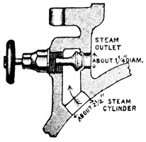
Fig. 2.
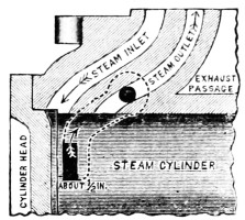
Fig. 3.
This style of cushion port makes the pump safer in case cushion valves are unskillfully left open too wide and tends to prevent a pump from pounding itself to pieces in case of a sudden release of load, as by a break in suction or delivery mains, or by a temporary admission of air to suction pipe.

Fig. 4.
Pumps made with this form of cushion release, have given very satisfactory results, and if the ports are properly located, there will be no re-bound of piston.
c. Cushion valves must be always provided with hand-wheels marked as per sketch, for the reason that very few men in charge of fire-pumps are found to clearly understand or to remember their use.
The lettering must be very open, clear and distinct, not liable to be obscured by grease and dirt, and of a permanent character.
It is desirable that spindle or wheel be so formed that a monkey wrench can get a grip to open a jammed valve. Fig. 5 shows the stem flattened for this purpose.
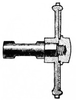
Fig. 5.
d. The valve and stem of cushion valve must be in one piece without any swivel joint.
Swivel joints are apt to come apart and make it impossible to operate the valve.
20. Piston Rods.
a. Piston rods for their entire length must be of solid Tobin Bronze, and the distinguishing brand of the manufacturers of this metal must be visible on at least one end of each rod.
b. The sizes must be not less than in table below.
Size of Pump. 500 gal. 750 gal. 1,000 gal. 1,500 gal.
Diameter of rod 2 inch. 21⁄4 inch. 23⁄8 inch. 21⁄2 inch.
c. The size and form of connection of rod to piston plunger and cross-head must be such that the stress in pounds per square inch at bottom of screw thread, or at such other point of reduced area as receives the highest tensile strain, shall not exceed 8,000 lbs. per square inch, when the steam pressure acting on the piston is 80 lbs. per square inch.
d. Piston rod nuts, in both steam and water ends, must be tightly fitted, and preferably of a finer thread than the United States Standard. This is to avoid as much as possible the unnecessary weakening of the rod at the bottom of the thread, and to reduce the tendency of the nut to work loose.
In practice 8 threads per inch has been found to give good satisfaction.
e. In addition to a tightly fitting nut, some reliable device must be provided, in both steam and water ends, for absolutely preventing these nuts from working off.
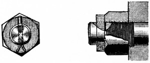
Fig. 6.
Fig. 6 shows one form of such a locking device and illustrates the kind of security desired.
This device combines the advantage of a taper key and a split pin, and the elongated key-slot gives sufficient leeway to always insure that the key can be driven up tight against the nut and thus prevent it from even starting to work off. Other methods will be approved in writing, if found satisfactory.
21. Valve Rods.
a. Valve Rods for their entire length must be of solid Tobin Bronze, with sizes not less than in table below.
Size of Pump. 500 gal. 750 gal. 1,000 gal. 1,500 gal.
Diameter of rod 1 inch. 11⁄8 inch. 11⁄8 inch. 11⁄4 inch.
b. The net area of valve-rod at its smallest section subject to tensile stress, must not be smaller than at bottom of U. S. standard screw thread on rod of diameter given above.
The construction of this rod as affecting lost motion at slide valve is specified under Article 15.
22. Stuffing Boxes.
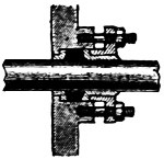
Fig. 7.
a. All six stuffing boxes must be bushed at the bottom with a brass ring with suitable neck and flange, and the follower or gland must be either of solid brass, or be lined with a brass shell 3⁄16-inch thick, having a flange next the packing, as shown in the sketch.
The bottom of stuffing boxes and the end of glands should taper slightly towards the center as per sketch.
b. These glands should be strong enough to withstand considerable abuse, so as not to break from the unfair treatment of unskilled men.
23. Pressure Gauge.
a. A pressure gauge of the Lane double tube spring pattern with 5 inch case must be provided and attached to the steam chest inside the throttle valve.
The dial of gauge should be scaled to indicate pressures up to 120 lbs. and be marked “STEAM.”
This kind of gauge is used on locomotives and is the best for withstanding the vibration which causes fire-pump gauges to be often unreliable. Moreover, this double spring is safer against freezing.
24. Drain Cocks.
a. Four brass drain cocks, each with lever handle and of one-half inch bore, are to be provided, and located one on each end of each steam cylinder.
Care should be taken to select a pattern of cock whose passageway is the full equivalent of a 1⁄2-inch hole. Some patterns of 1⁄2-inch commercial cocks although threaded for 1⁄2-inch pipe thread have but a 1⁄4-inch hole through them. Such are not acceptable.
25. Oiling Devices.
a. A one-pint hand oil pump, to be connected below the throttle, and a one-pint sight feed lubricator, to be connected above the throttle, must be furnished with each pump.
b. Oiling holes must be provided for all valve motion pins, and for each end of both rock shafts.
26. Stroke Gauge.
a. A length-of-stroke-index must be provided for each side of pump. These must be of simple form for at all times rendering obvious the exact length of stroke which each piston is making, and thus calling attention to improper adjustments of cushion valves or stuffing boxes.
b. The gauge piece over which the index slides must have deep, conspicuous marks at ends of nominal stroke, and also light marks at extreme positions; it need contain no other graduations.
c. This stroke index must be rigidly secured to cross-head in such a way that it cannot get loose or out of adjustment.
THE WATER END.
27. Water Cylinders.
a. These must be of hard close iron with metal so distributed as to ensure sound castings, and freedom from shrink cracks.
b. The design should be along lines best calculated to resist internal pressure so as to avoid as much as possible the need of ribs for stiffening.
c. They must be capable of withstanding, without showing signs of weakness, the pressures and shocks due to running under the conditions mentioned in Chapter “Tests for Acceptance,” Art. 48-54.
The suction chamber should be able to withstand a water pressure of 100 lbs.
Although suction chambers are not regularly subject to a pressure, it is sometimes desired to connect them to public water supplies, and where foot valves are used there is a chance of getting pressure on the suction, so that ample strength is necessary.
Foundry finish may be permitted on the joints at water cylinder heads and at hand-hole plates, provided surfaces are so true that a rubber packing not over 1⁄16 of an inch in thickness is sufficient to secure perfect tightness.
d. Conveniently placed hand-holes of liberal size must be provided for the ready examination and renewal of valve parts at the yoke end of water cylinders and in the delivery chamber.
This will necessitate holes not less than 6 × 8 inches, or its equivalent, for the two largest-size pumps, and holes proportionately as large for the 500 and 750-gallon pumps. The easy access to the valve parts is of vital importance, and must receive careful attention.
e. The thickness of metal for cylinder shell, valve decks, partitions, ribs, etc., will depend largely upon the form of construction, but, in a general way, to establish safe minimums for the average water cylinder, of nearly cylindrical form, whose flat surfaces are stiffly ribbed, we submit the table below:
Size of Pump. 500 gal. 750 gal. 1,000 gal. 1,500 gal.
Thickness of cylinder shell when of nearly cylindrical form Inches. Inches. Inches. Inches.
7⁄8 1 11⁄8 11⁄4
Thickness of valve decks when well ribbed 11⁄4 11⁄4 11⁄4 11⁄4
Thickness of transverse partition, depending on ribbing 11⁄4 to 11⁄2 11⁄4 to 11⁄2 11⁄2 to 2 11⁄2 to 2
Thickness of longitudinal partition, depending on ribbing 11⁄4 to 11⁄2 11⁄4 to 11⁄2 11⁄4 to 2 11⁄2 to 2
Thickness of ribs 3⁄4 7⁄8 1 1
Thickness of suction chamber 5⁄8 3⁄4 3⁄4 7⁄8
Thickness of delivery chamber 7⁄8 1 11⁄8 11⁄4
Lighter construction than herein specified will not be regarded as satisfactory, and any construction will be finally passed upon on examination of drawings.
f. The bolting of all parts of the water end is to be of such strength that the maximum stress at bottom of screw thread will not exceed 10,000 lbs. per square inch (disregarding for the moment the initial stress due setting up nuts) for a water pressure of 200 lbs. per square inch, computed on an area out to centre line of bolts.
No stud or bolt smaller than 3⁄4-inch should be used to assemble parts subject to the strain of water pressure, as smaller bolts are likely to be twisted off.
Although these pumps are not expected to be designed for a regular working water-pressure of 240 or 320 lbs., it is expected that bolts, shells, rods, etc., will be figured to stand this comparatively quiet, temporary, high pressure, exclusive of further allowance for initial strain due setting up of bolts, with a factor of safety of at least four.
This high test pressure is analogous to the custom of proving all common cast-iron water pipes to 300 lbs. and all common lap-welded steam pipes to 500 lbs. per square inch, and common water-works gate valves to 400 lbs., even though these are to be regularly used at much less pressure.
We are assured that castings no heavier than at present used by the best makers will stand this test, if properly shaped and liberally bolted.
g. For requirements for stuffing boxes, see Art. 22.
28. Water Plungers and Bushings.
a. The “inside plunger and bushing” is preferred for all situations where the water is free from grit or mud.
b. Water-plungers must be of solid brass or bronze, and the bushing in which they slide must also be of brass or bronze. The composition of the plunger and its bushing should be of very hard, though dissimilar alloys, to ensure good wearing qualities.
For material and size of piston rods and lock for nuts, see Art. 20.
With poor alignment or bad workmanship or lack of skill in mixing the alloys, brass plungers are liable to score and give trouble; but with proper selection of alloys and true cylinders accurately aligned, they can be made to run all right wherever iron ones can. It is quite a fine point to get these wearing surfaces just right; and this is wherein the experience, skill and shop practice of one maker is likely to be much superior to that of another working under the same specification.
c. The length of machined cylindrical bearing within the partition must be not less then 2 inches. The plunger bushing must have a faced seat transverse to its axis against partition, forming a water-tight ground joint not less than one-half inch wide.
Any rubber gasket or other compressible packing for making this joint water-tight is not acceptable.
d. The construction of bushing and hole in partition must be such that a cylindrical shell for use with a packed piston can be interchangeably inserted in its place and secured by the same bolts.
This can readily be arranged and enables a packed piston to be inserted in place of a plunger subsequent to the installation of the pump with a minimum of expense, should this become desirable from change of conditions at any future time.
e. Small transverse grooves cut within the sliding surface of the plunger bushing, with a view to lessen the leakage, are not acceptable.
Although a slight advantage in this respect for clean water, they are a disadvantage on the whole, as dirt catches in them in the ordinary situation and cuts the plungers.
29. Standard Dimensions of Plungers and Plunger Bushings.
a. To bring all these expensive parts to the same standard of weight and bearing surface, the following dimensions are specified as the least that will be acceptable. These are based on a length of plunger which uncovers the bushings one inch at end of nominal stroke.
SOLID BRONZE PLUNGERS AND BUSHINGS.
Size of Pump. 500 gal. 750 gal. 1000 gal. 1500 gal.
Plunger.
Diameter 7 or 71⁄4-in. 9-in. 10 or 101⁄4-in. 12-in.
Length 17-in. 17 „ 18-in. 24 „
Thickness of transverse partition 5⁄8 „ 5⁄8 „ 3⁄4 „ 3⁄4 „
Thickness next to partition 1⁄2 „ 1⁄2 „ 5⁄8 „ 3⁄4 „
Thickness next to end 5⁄16 „ 3⁄8 „ 3⁄8 „ 1⁄2 „
Number of ribs 4 4 6 6
Thickness of ribs 5⁄16 „ 5⁄16 „ 3⁄8 „ 3⁄8 „
Bushing.
Length 7 „ 7 „ 8 „ 10 „
Thickness at end 5⁄16 „ 3⁄8 „ 3⁄8 „ 1⁄2 „
Thence tapered evenly to a thickness next to bearing of not less than 1⁄2 „ 5⁄8 „ 5⁄8 „ 3⁄4 „
Thickness at the center bearing not less than 3⁄4 „ 3⁄4 „ 3⁄4 „ 13⁄16 „
30. Water Pistons and Bushings.
a. The “water piston with fibrous packing” is preferred for many situations in the West or South, or for water containing grit or mud, like that of the Ohio River; and, for the comparatively few cases where pump pressure governors are used, the packed piston will give better service and longer wear.
b. The removable bushing or cylinder in which this piston works must be of solid bronze.
c. As stated in Art. 28 d, this bushing should be so constructed as to be readily interchangeable with the bushing of the inside plunger type.
d. The length of bushing must be such that the ends of piston will barely come short of the edges of cylinder at contact stroke and not uncover.
e. The thickness of the cylindrical bushings must be not less than is given in the following table:
BUSHINGS FOR PACKED WATER PISTONS.
Size of Pump. 500 gal. 750 gal. 1000 gal. 1500 gal.
Solid Bronze.
Thickness at extreme end 7⁄16-in. 1⁄2-in. 1⁄2-in. 9⁄16-in.
Tapered evenly from end to a thickness next to bearing of not less than 9⁄16 „ 5⁄8 „ 11⁄16 „ 3⁄4 „
Thickness at center bearing at least 3⁄4 „ 3⁄4 „ 3⁄4 „ 13⁄16 „
f. In other respects, the specifications for plunger bushings, already given in Art. 28, will apply to the above.
g. The water piston used in the shell described above must expose not less than 2 inches in width of fibrous packing, and must be of bronze, with disc and follower accurately turned to a sliding fit, so that the leakage past it will be a minimum, even when no fibrous packing is in place. There must be at least 2 inches in length of metallic bearing on both disc and follower.
The follower must be accurately centered and fitted to hub of piston, so that alignment will not be disturbed if taken apart.
h. The water piston must be of simple and strong construction, with follower bolts tightly fitted, and with fibrous packing so cut as to prevent by-passing.
i. All materials used in construction of piston, except packing, must be brass, bronze, or other non-corrosive metal.
j. Bushing studs must be of Tobin Bronze, and of such size and number, that the maximum stress at the bottom of the screw thread shall not exceed 10,000 lbs. per square inch, in the event of plunger becoming fast in the bushing with 80 lbs. of steam in the steam cylinders.
k. For each bushing stud there must be provided a composition nut and check nut.
l. All minor parts exposed to the action of water in water cylinder, that are not herein specified, must be of brass, bronze, or other non-corrosive material.
31. Pump Valves.
a. All the suction and discharge valves in any one pump must be of the same size and interchangeable.
b. There must be a clear space around each rubber valve, between it and the nearest valve, equal to at least one-fourth of the diameter of the valve, or between it and the wall of the chamber of at least one-eighth of the diameter of the valve.
c. These valves must be of the very best quality of rubber, of medium temper, with a face as soft as good wearing quality will permit.
They must be double-faced, so they can be reversed when one face is worn.
The quality of rubber is almost impossible of determination by brief inspection or by chemical analysis. The relative amount of pure gum and of cheaper composition may vary, or good material may be injured by defective vulcanization. The only safe way to secure excellence and uniformity is for the pump manufacturer to test samples of each new lot under severe duty (as by a week’s run in a small special pump, with say 150 pounds pressure and heavy water hammer, or by some equivalent means) and to furthermore require the rubber manufacturer to mould a date mark as “(Name of pump manufacturer, lot 201—April 3, 1904.)” on the edge of every valve, by which the pump manufacturer can keep track of those which prove defective.
32. Size and Number of Pump Valves.
a. The diameter of the disc of rubber forming the valve must not be greater than 4 inches or less than 3 inches. Three and a half inches diameter is probably the most favorable size, but is not insisted upon.
There is some confusion between different shops about designating size of valves. The practice is here adopted, which is much the most widely used, of naming the diameter of the disc of rubber which covers the ports, and it is hereby specified that this shall be about 1⁄2-inch greater than the diameter of the valve-port circle which it covers, thus affording about 1⁄4-inch overlap or bearing for the rubber disc all around its edge.
If valves are larger than 4-inch there is an increased tendency to valve-slam at the very high speed at which the pump is designed to run, and if valves are smaller than 3 inches diameter the greater number tends to unnecessary multiplication of parts, and the ports being so small are a little more liable to become obstructed by rubbish.
b. The thickness of the rubber valve must in no cases be less than 5⁄8-inch.
33. Suction Valve Area.
a. The total lift of suction valves must not exceed 1⁄2-inch.
b. The net suction valve port area and the total suction valve outlet area under valves lifted 1⁄2 inch high must not be smaller than the figures given in the table below.
(1) Length of Stroke (in inches) 12 16
(2) Greatest No. revolutions per minute. 70 60
(3) Corresponding Piston travel per minute. 140 160 ft.
Approx. actual max. Piston velocity at full speed, per row (3) × 2.2. (4) Feet per minute. 308 352
(5) Feet per second. 5.1 5.9
(6) Net Suction Valve-port area speed regarded necessary for this per cent. of Plunger area. 56% 64%
(7) Total Suction Valve Outlet Area under Valves lifted 1⁄2 in. high. 56% 64%
(8) Discharge Valve Area. 2/3 of Suction Valve Area.
By “valve-outlet area,” we mean the vertical cylindrical surface over the outer edge of the valve ports, i.e., the distance L multiplied by the circumference at the outer edge of the valve ports C, Fig. 8. Thus for a 4-inch valve, with ports inscribed in a 31⁄2-inch circle, whose circumference is 3·5 × 3·1416 = 11 inches; the valve “outlet area” for 1⁄2-inch lift would be 51⁄2 inches.
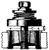
Fig. 8.
The actual velocity of piston during the middle portion of stroke is from 2.0 to 2.4 (average 2.2) times as great as the piston travel per minute (as determined in experiments by Mr. J. R. Freeman on several duplex pumps of different manufacture). This is because each piston stands still nearly half the time, or while its mate is working, and, moreover, moves more slowly near start and finish of stroke. The words “piston speed” are commonly incorrectly used and refer to “piston travel.” A clear understanding that the actual piston speed is more than twice as great leads to more generous valve design.
Large aggregate valve areas are necessary for pumps designed to run as fast as these, and experience has shown that to prevent valve slam at high speed and to accommodate high suction lifts, it is just as important to have a large “valve outlet area” as to have a large area of valve port.
It is valve slam or water hammer which commonly limits the highest speed at which a pump can be run. This water hammer may originate from the pulsations in a long or small suction pipe. The vacuum chamber lessens it, but there is commonly some point of high water in the vacuum chamber that will give much smoother action than any other.
Valve slam in this style of pump is caused chiefly by the short rebound of the steam piston against the elastic steam cushion at the end of the stroke. This in turn snaps the valves down with a jump when the speed is high. Dividing this impact or slam on numerous valves of low lift, tends to break up and lessen the shock, therefore with valves of the size and style used in fire-pumps, other things being equal, the less they have to rise and drop to let the water through them, the less will be the valve slam. This height of rise and drop is governed by the circumference rather than the port area. Experience and practice has shown that a 1⁄2-inch limit of lift is reasonable and does ensure a smooth working pump under all ordinary conditions.
c. The following table gives minimums for aggregate valve port area and aggregate valve outlet area, for the different size plungers, figured on a basis of 56% of plunger area for a 12-inch stroke, and 64% for a 16-inch stroke.
Size of Pump. 500 gal. 750 gal. 1000 gal. 1500 gal.
1 Diameter of plunger. Inches 71⁄4″ 9″ 10″ 12″
2 Area of plunger in sq. inches 41·28 63·62 8·54 113·10
3 56% of plunger area,or Minimum aggregate valve port area allowed per section. Square inches 23·11 35·63 43·98 64% = 72·38
4 Minimum aggregate valve port circumference, allowed per section. Inches 46·22 71·26 87·96 144·76
5 Minimum aggregate valve outlet area allowed per section for valves lifted 1⁄2 inch high. Square inches 23·11 35·63 43·98 72·38
d. If we consider using any one of the three sizes of valves below, whose port areas may be assumed approximately as
Diam. Valve. Diam. of Valve Port. Circ. Circ. of V. C. Circle. Valve Port Area (Net). Square inches.
3″ 21⁄2″ 7·85″ 3·5
31⁄2″ 3″ 9·42″ 4·7
4″ 31⁄2″ 10·99″ 6·3
given, then the necessary number of valves per section will be as in the table following:
Size of Pump. 500 gal. 750 gal. 1000 gal. 1500 gal.
Size of Valves. 3″ 31⁄2″ 4″ 3″ 31⁄2″ 4″ 3″ 31⁄2″ 4″ 3″ 31⁄2″ 4″
Necessary number of valves to satisfy (4) under c 6 5 5 9 8 7 11 10 8 19 16 14
Necessary number of valves to satisfy (3) under c 7 5 4 10 8 6 13 10 7 21 16 12
The exact number and size of valves will, however, not be insisted upon provided the aggregate valve area and the aggregate valve outlet area for each section is not less than that given in the table under c for the limiting lift of 1⁄2 inch.
Manufacturers will note that with the established lift of 1⁄2 inch, the 31⁄2-inch valve will permit a valve outlet area more nearly equal to its port area than will either the 3-inch or 4-inch valves, and a relatively less number of valves will satisfy the specifications.
34. Delivery Valves.
a. The total lift of delivery valves must not exceed one-half inch.
This is to avoid valve slam, as explained in Art. 33.
b. The aggregate valve-port area should be restricted to about two-thirds the suction-valve area.
A small restriction of water-way through the delivery valves steadies the action of the pump and tends to prevent undue pulsations of pressure in the delivery pipe or fire hose. Fewer delivery valves than suction valves are, therefore, preferred, and if extra holes in the delivery deck are cast for shop purposes these had better be plugged than fitted with valves.
The suction valves require more generous port-circumference and port-area than delivery valves because when a pump has to suck its supply through a considerable height or through a long pipe there should be the least practicable waste of the atmospheric pressure in getting the water into the plunger chamber, or in retarding it from following the plunger in full contact. With the water once into the plunger chamber there is plenty of steam pressure available to force it out through the delivery valves.
35. Valve Springs, Guards and Covers.
a. All valve springs must be of the best spring brass wire, and must be coiled on a cylindrical arbor.
Conical valve springs are not approved because the strain is not uniform throughout spring, thereby increasing the liability to breakage and the chance of their getting out of center and becoming “hooked up.”
b. The valve spring must be held centrally at its top by resting in a groove in valve guard, substantially as shown in Fig. 9.
c. A light, rustless metallic plate must be interposed between the bottom of the spring and the rubber valve, and must be the full area of the valve. This plate must also be formed with a raised bead to guide the spring at the bottom.
The weight of this plate should be small, for the inertia of the lifting parts of the valves should be the least possible, to permit quick action and to avoid pounding.
d. For the average condition of a 10 or 15-foot lift, the stiffness of suction valve springs should be such that a force of about one pound per square inch of net port area will lift valve 1⁄4 inch off its seat.
The springs on the delivery valves should ordinarily be from two to three times as stiff as just specified, but any other reasonable degree of stiffness which is proved to work well in practice will not be objected to.
For suction under a head, the greater snap with which water enters the plunger chamber when thus pushed in by say twice the atmospheric pressure renders it difficult to avoid water hammer at high speed. Extra stiff suction valve springs will commonly aid in controlling this and should be used wherever pumps are to work under a head.
An approved type of indicator water gate on the suction pipe near the pump, which can be partly closed, will enable the pump to run quietly at high speed. Such a gate is an extra not included in price of the pump.
36. Sticking of Valves.
a. Steam fire-pumps should be started, to limber them up, at least once a week.
Although vulcanized India-rubber is much the best material yet used for fire-pump valves, unfortunately the brass is sometimes corroded by the free sulphur contained in the rubber, so that if the pump is left standing for several weeks the rubber valve discs may become stuck to their brass seats, and, if suction has a high lift, there may not be vacuum enough to tear all the suction valves open when pump is started.
37. Valve Seats.
a. All water valve seats must be of bronze composition. They may be either screwed into the deck on a taper or forced in on a smooth taper fit. With either arrangement, the seat must be either flanged out on the under side all the way round or be provided with a substantial lug opposite each rib, these lugs being expanded out after the valve is inserted.
If the valve seats are not expanded after being put in place, there is a possibility that now and then a valve seat will work loose and come out, thus crippling the pump.
b. The under side of the valve deck must be rounded over to give good bearing for the expanded part of the seat.
c. Three-inch valves must have four or five ribs, three and a half inch valves five or six ribs, and four inch-valves six ribs.
Enough ribs must be provided to give proper support to the rubber valve, but too many are objectionable, as small ports would be liable to obstruction by refuse.
d. The edges of the valve-seat ports must be moderately rounded over, to remove such sharp edges and points, as would be liable to cut, or damage the rubber valve when under pressure.
38. Valve Stems.
a. All valve stems must be of 3⁄4-inch Tobin bronze and of the fixed type, and must have the guard fastened on by one of the methods shown in Figs. 9 and 10.
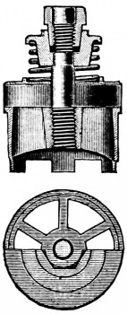
Fig. 9.
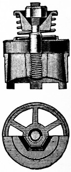
Fig. 10.
Other methods may be approved, in writing, if found by test and experience to have especial merit.
b. These stems must be screwed into the seats on a straight, tightly fitting thread, and the lower end then well headed over into a countersink. The valve guard and nut must be of composition.
In Fig. 9 the upper part of the stem is slabbed off on two opposite sides and fits a corresponding hole in the guard.
The guard, therefore, cannot turn. The outside of the special nut is fitted on a taper to the inside of the guard, and the nut tapped out to fit the 5⁄8 U. S. thread on the stem.
The action of the valve, whether with the spring or without, tends to drive these taper fits together, producing a frictional lock similar to that of a friction clutch; and although the nut may be loose on the thread, it cannot possibly work off.
It will be apparent that the taper fit on the nut must be so made as to always bear on the taper fit in the guard, and not bottom in the guard.
It is believed that with the present screw machine practice in shops of to-day these small parts can readily be turned out accurately and cheaply in large quantities. The nuts and guards made in any one shop must be exactly of standard dimensions, so that the product of different periods will be interchangeable.
The taper should be about one inch to one foot. With this taper the nut can be readily turned in or out, but there is friction enough to hold the guard and nut together even if the spring is off.
In Fig. 10, the top of the guard is recessed in the form of a hollow inverted pyramid of six sides, to correspond to a hexagonal nut. The angle of two opposite sides of this recess, which should be about 75 degrees, will both surely lock the nut and still permit of its being turned with a wrench.
The guard is kept from turning by slabbing off the stem, in the same manner as described and shown in Fig. 9.
To facilitate the removal of the nut, the edges should be slightly chamfered. An unfinished nut simply drilled and tapped is all that is desired. Any hexagonal or square nut within the size of the tapered recess will be locked.
With this construction, the nut cannot turn in either direction without compressing the spring and is therefore locked, and, in the event of the spring breaking or being left off, the nut is well protected in its recess from the possible turning effects of water currents, and experiments have shown that it will still stay in place.
With machine molding it will be possible to make these guards complete in foundry, requiring no machine work further than a possible broaching out of hole to fit the stem, as a fairly good fit is necessary.
While both of these devices are effective even though not tightened down to a shoulder, they should be so tightened for greater safety and to fix the lift at the half-inch limit.
39. Pipe Sizes.
a. Water and steam pipe connections must have standard flanges to connect with pipes of the sizes given below.
Size of Pump. Gal. Per Min. Diameter of Suction Pipe. Inches. Diameter Discharge Pipe. Inches. Steam Pipe. Exhaust Pipe.
500 8 6 3 4
750 10 7 or 8 C 31⁄2 4
1,000 12 8 4 5
1,500 14 10 5 6
FOOTNOTE:
b. A single suction entrance at the end of the pump is to be provided unless otherwise specified by the purchaser.
Some situations render desirable side suction entrances, for permitting drafting water from two different sources of supply. These additional openings are to be considered as extras. Ordinarily, the purchaser can provide for such situations by proper piping at the single end suction entrance.
If there is to be but one suction opening on casting, this had best be at center, for the reason that, if suction pipe ever gets to leaking air, this air stands a better chance of being distributed equally to the two plungers, and has less tendency to make the pump run unevenly.
c. Standard flanges and standard bolt layouts as adopted by the Master Steam Fitters, July 18, 1894, must be used on all the above pipe connections, as per table given below.
SCHEDULE OF STANDARD FLANGES.
Size of Pipe × Diam. of Flange. Diameter of Bolt Circle. Number of Bolts. Size of Bolts. Flange Thickness at Edge.
Inches. Inches. Inches. Inches.
3 × 71⁄2 6 4 5⁄8 × 21⁄2 13⁄16
31⁄2 × 81⁄2 7 4 5⁄8 × 21⁄2 7⁄8
4 × 9 71⁄2 4 3⁄4 × 23⁄4 15⁄16
41⁄2 × 91⁄4 73⁄4 8 3⁄4 × 3 15⁄16
5 × 10 81⁄2 8 3⁄4 × 3 15⁄16
6 × 11 91⁄2 8 3⁄4 × 3 1
7 × 121⁄2 103⁄4 8 3⁄4 × 31⁄4 11⁄16
8 × 131⁄2 113⁄4 8 3⁄4 × 31⁄2 1⁄8
9 × 15 131⁄4 12 3⁄4 × 31⁄2 11⁄8
10 × 16 141⁄4 12 7⁄8 × 35⁄8 13⁄16
12 × 19 17 12 7⁄8 × 33⁄4 11⁄4
14 × 21 183⁄4 12 1 × 41⁄4 13⁄8
Do not drill bolt holes on center line, but symmetrically each side of it.
On steam and exhaust openings loose flanges threaded for wrought-iron pipe must be provided.
Where the situation will not permit of a standard flange on exhaust opening for lack of room, a special flange threaded to fit the proper size wrought-iron pipe may be used.
40. Air and Vacuum Chambers.
a. Air and vacuum chambers in accordance with the sizes given in the following table must be provided with all pumps. If the air chamber is cast iron, the pump manufacturers must warrant that it has been subjected to a hydraulic test of 400 lbs. per square inch before it is connected to pump.
It is to be thoroughly painted inside and out to diminish its porosity.
SIZE OF VACUUM AND AIR CHAMBERS.
Vacuum Chamber is to contain:— Air Chamber is to contain:—
500-gallon pump. 13 gallons. 17 gallons.
750 „ „ 18 „ 25 „
1,000 „ „ 24 „ 30 „
1,500 „ „ 30 „ 40 „
The air chamber, combined with connections for discharge pipe, relief valve, and hose valves, should be carefully designed to make the whole weight as small as possible. Keeping this weight down makes the pump run steadier and brings less strain on the flanges at high speeds.
An air chamber of hammered copper and warranted tested under a hydraulic pressure not less than 300 lbs. per square inch is a little better than cast iron as it holds air better, and being lighter it wrenches and strains the pump less when running fast and shaking, but because it costs from $25 to $50 more than cast iron, it is not often adopted.
b. The vacuum chamber must be attached to the pump in the most direct way practicable, but provision must be made for attaching it in such manner as not to prevent readily taking off the cylinder heads.
c. Every vacuum chamber should be provided on one side near the top with a 1⁄4-inch pipe hole plugged. This to be used for attaching a vacuum gauge if desired.
41. Pressure Gauge.
a. A pressure gauge of the Lane double tube spring pattern with 5-inch case, must be provided with the pump, and connected near to inboard side of air chamber, as shown in Fig. 12, by a 1⁄4-inch cock, with lever handle.
The dial of this gauge should be scaled to indicate pressures up to 240 lbs. and be marked “WATER.”
This kind of gauge is used on locomotives and is the best for withstanding the vibration which causes fire-pump gauges to be often unreliable. Moreover, this double spring form is safer against freezing.
42. Hose Valves.
a. Hose valves must be attached to the pump (and included in its price) as follows:—
For the 2 stream or 500-gal. pump, 2 hose valves. For the 3 stream or 750-gal. pump, 3 hose valves. For the 4 stream or 1,000-gal. pump, 4 hose valves. For the 6 stream or 1,500-gal. pump, 6 hose valves.
These are to be 21⁄2-inch straightway brass valves, without cap, and similar and equal in quality to those made by the Chapman Valve Company, the Ludlow Valve Company, or the Lunkenheimer Company.
The hose-screw at end of these valves is to be fitted to a hose coupling furnished by the customer, or where this cannot be procured may be left with the thread uncut.
To accommodate locations where all the lines of hose must lead off from one side of the pump—makers can furnish a spool piece or special casting to which the hose valves can be attached—but this is an extra not included in the regular price.
43. Safety Valve.

Fig. 11.
a. A safety or relief valve of the Ashton, Crosby, American, or other make agreed upon in writing with this office, is to be regularly included in the price, and is to be attached to each pump; preferably extending horizontally inboard from base of air chamber, as shown in Fig. 12, so that its hand-wheel for regulating pressure is within easy reach. This hand-wheel must be marked very conspicuously as shown in Fig. 11.
b. This valve is to be set ordinarily at a working pressure of 100 pounds to the square inch, and is to be of such capacity, that when set at 100 pounds it can pass all the water discharged by the pump at full speed, at a pump pressure not exceeding 125 pounds per square inch.
For 500-gallon pump a 3 inch valve. For 750-gallon pump 31⁄2 inch valve. For 1,000-gallon pump 4 inch valve. For 1,500-gallon pump 5 inch valve.
The relief valve must discharge in a vertical downward direction into a cone or funnel secured to the outlet of the valve. (See Art. 44.)
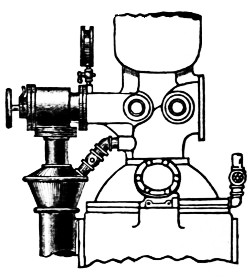
Fig. 12.
The valve must be so attached to the delivery elbow and discharge cone by flange connections as to permit of its ready removal for repairs without disturbing the waste piping.
44. Discharge Cone.
a. This cone should be so constructed that the pump operator can easily see any water wasting through the relief valve, and its passages should be of such design and size as to avoid splashing water over into the pump room.
b. The cone must also have a one-inch tapped connection for the air-vent pipe required by Art. 45, and the arrangement must be such that the pump operator can easily tell whether water is coming from the air pipe or is wasting through the relief valve.
c. The cone should be piped to some point outside of the pump house where water can be wasted freely, the waste pipes being as below.
SIZE OF PUMP. DIAMETER OF WASTE PIPE FROM CONE.
500-gallon. 5 inches.
750 „ 6 „
1,000 „ 7 „
1,500 „ 8 „
The waste pipe can pass down to floor between the yokes at middle of pump. It should be piped in such a way that steam and gases from other drains or waste pipes will not work back through it, and, by being troublesome in the pump room, suggest the covering of the cone in any way, as it is desirable that the pump operator should always be able to see instantly any waste from the relief valve or air vent.
This cast-iron cone, connected to the safety valve and air vent, is included in price of pump, but the waste pipe beyond it is not.
45. Air Valve.

Fig. 13.
a. An air vent with a brass gate valve and brass pipe for connecting up, must be provided and connected with delivery elbow and discharge cone.
b. The size of this air vent should be one inch for 500-gallon and 750-gallon pumps, and one and one-fourth inches for the 1000-gallon and 1500-gallon sizes.
c. The hand wheel of this valve must be marked as per Fig. 13. The lettering must be very open, clear and distinct, not liable to be obstructed by grease and dirt, and of a permanent character.
The object of this valve is to reduce the pressure above force valves and secure a prompt riddance of all air that may come through the water cylinders when first starting up.
This valve, of course, should be closed when once pump is under way, to prevent waste of water.
46. Priming.
a. Each pump must be fitted with a set of brass priming pipes and valves, according to either one or the other of the following methods:
b. For 1,000 and 1,500 gallon pumps, the priming pipes must be 11⁄4 inches. For the 500 and 750 gallon pumps, the pipes must be 1 inch. Pump-makers are to furnish these pipes and the fittings called for below, and are to connect them up providing a 2-inch outlet, looking upwards, ready for the supply from the priming tank.
The pipe from the priming tank to this outlet should be at least 2-inch, and may be of iron, and is to be furnished by the purchaser. All parts furnished by the pump-maker are to be of brass, and are to be included in the price of the pump.
Controllable Valve Arrangement.
c. Four 2-seat controllable valves, one for each pulsation chamber, and of the general type illustrated in Fig. 14, must be provided. In these the inlet of water and outlet of air are simultaneously opened and closed by the pump operator.
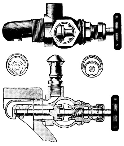
Fig. 14.
Objection has been raised to this double-seated valve from the possible difficulty of keeping both seats tight. If desired, the valve may be fitted with a flange instead of a screw connection, and the stem between the two seats somewhat enlarged and provided with a suitable spring, thus giving flexibility between the two seats and preventing all trouble from uneven wear.
d. The hand-wheel of each of these valves must be marked as per Fig. 15, so that the pump operator I may clearly understand their use. The lettering must be very open, clear and distinct, not liable to be obscured by grease and dirt, and of a permanent character.

Fig. 15.
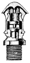
Fig. 16.
e. There must be provided and fitted to each combined valve a check and umbrella-top air vent, as shown in Fig. 16. This fitting must have a clear passageway through it, the full equivalent of a 1⁄2-inch bore.
The check-valve is to permit the outflow of air, but to prevent the influx when the plunger is sucking.
This method is preferred to the one using rubber priming checks, as now and then a rubber valve will stick on its seat and thus prevent priming of one of the chambers. In this arrangement the pump operator has absolute control over the priming water into each chamber.
Another advantage is that the connection of the air-vent with the priming valve ensures that the air-vents will be opened; and further, by the vigorous spurting out of water as soon as the pump is primed, the pump operator is reminded that the priming valve should be closed.
Should the pump operator, however, through a mistaken idea of the proper method of operation, think that the priming should be continued until all air was exhausted from the suction pipe and the pump running in normal condition, there would be some by-passing between chambers, but as there is a free vent for the air, the main result would be simply to limit the amount of air exhausted per stroke, from the main suction, by the amount of water which entered a chamber in this way. The amount of water thus entering, however, would not be appreciably greater than that which would enter from the priming-tank with the check-valve arrangement.
If, even in spite of the warning given by the spurting air-vents, the pump operator should neglect to close the priming-valves when the pump was running normally, the priming-tank would eventually be overflowed; but this would not be as serious as the drawing in of air from an exhausted priming-tank, which would result with the check-valve method, were the main 2-inch valve similarly neglected.
Rubber Check Valves.
f. Four rubber check valves, one for each pulsation chamber, and similar to ordinary pump valves, must be provided. The chambers for these should preferably be made as a part of the pump cylinder, thus securing a compact arrangement.
Figure 12 shows this arrangement in outline.
g. The valve seat should have three ribs to the central hub, supporting the rubber valve. The net port area through the valve should be not less than 11⁄2 square inches.
This valve seat should rest in an inverted position, and can be so fitted up as to be readily removed. The valve stems can be of the removable type screwing into the seat, but must be made long enough to receive a check nut on the opposite side of seat. This will effectually lock the stem in place.
h. Care must be taken to arrange the water passages through and about these priming checks, so as to avoid all air pockets and so as to reduce to a minimum the possibility of the valves becoming choked up by refuse.
i. The valve seats, stems and all parts must be of composition and of strong rugged design, so fitted up that there is the least chance for the rubber valves to stick, and with all parts securely put together the valves must be readily accessible.
j. The valve springs must have only sufficient strength to keep the valves on their seats, so that they will freely open even with the low head of priming water often existing.
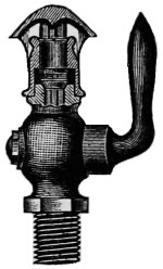
Fig. 17.
k. There must be provided, and attached to the top of each plunger chamber, a brass check valve and air cock with umbrella top, as shown in Fig. 17. This cock and valve must have a clear passageway through them—the full equivalent of a 1⁄2-inch bore.
The check valve is to permit the outflow of air, but to prevent the influx when the plunger is sucking. Cocks with lever handles are used, as these show clearly whether they are open or shut.
l. There must also be provided a 2-inch brass gate valve for the general control of the water to the four-check valves. The hand wheel of this valve must be marked as per Fig. 15. The lettering must be very clear, open, and distinct, not liable to be obscured by grease, and of a permanent character.
It is essential for a properly working pump that the main 2-inch priming-valve should be closed as soon as the pump is primed. Otherwise, water will be drawn from the priming tank, lessening the lifting power of the pump through the main suction, and if this is continued the priming tank will often be exhausted and air drawn into the pump, interfering with its proper action. It is for this reason that the marking on the priming valve is required.
For all average situations, either method of priming permits of getting the pump under way in a very few minutes, but, for cases where the suction pipe is over 300 or 400 feet in length, or sometimes where the lift is over 18 feet, or where there is a combination of long length and lift within these limits, so much time is consumed in exhausting the air from the suction pipe that it becomes desirable to supplement this method.
For such situations, a steam ejector connected to the suction pipe near the pump is advised, and may be required in addition to the regular priming pipes and tank. The size of the ejector should be sufficient to exhaust the suction pipe within about three minutes. Such ejectors will be considered as extras not included in the ordinary pump fittings.
For cases where pump can only take its suction under a head, if absolutely certain that the level of the suction water will never fall below level of center of pump, these priming pipes may be omitted, but openings for them into the pump shell must be provided and capped or plugged.
A foot valve on a fire-pump suction is not advised except in very rare cases, as with a lift of 18 feet or a suction pipe 500 feet or more long. A foot valve is not needed when there is a good efficient set of priming arrangements as described above and it is commonly found this gives a false sense of security, and that with a fire-pump left standing several days the water will often be found to have leaked back, so that it is no better than if no foot valve had been used.
A foot valve must of necessity generally be located where it is inaccessible for quick repairs, and as they grow old, foot valves are often a source of trouble. Where a suction pipe is exposed even slightly to frost, a foot valve is specially objectionable.
A priming tank is provided for the purchaser in all cases where there is ever to be any lift on the suction. It is generally advised that this tank have a capacity of one-half of what the pump can throw at full speed in a minute. This means 250 gallons for a 500-gallon pump and 500 gallons for a 1,000-gallon pump, etc. It is the intention to make the pump a truly “independent source” of supply, therefore the need of a special priming tank.
Older Priming Arrangements.
The form of priming arrangement heretofore used, with metal check valves, one main 2-inch priming valve, and 1-inch priming pipes, separate controllable air cocks, may be retained on all pumps at present in service, and will be considered satisfactory, if kept in good order.
If in any case such checks give trouble the priming arrangement may be changed and valves like Fig. 14 or rubber checks as described in sections f-j, made up in detachable form,D may be put on if desired, where the connections on the pump permit them.
Where neither method is desired or where neither is feasible the faulty checks may be replaced by a special type such as are now made for this use, by the Locke Regulator Company, of Salem, Mass. These are 1-inch check valves, adapted to use a small disc of medium hard rubber, similar to a pump valve.
These fittings are very near the dimensions of the commercial check valve, so that with slight shortening of piping connections they will fit into the present arrangements, and give satisfaction.
47. Drain Cocks.
a. Five brass drain cocks, each with a lever handle and of 1⁄2-inch bore, are to be provided, and located one on each end of each water cylinder, and one above the upper valve deck.
Care should be taken to select a pattern of cock whose passageway is the practical equivalent of a 1⁄2-inch hole. Some patterns of 1⁄2-inch commercial cocks although threaded for 1⁄2-inch pipe thread have but a 1⁄4-inch hole through them. Such are not acceptable.
FOOTNOTE:
TESTS FOR ACCEPTANCE.
48. Test for Smoothness of Action.
a. Provide outlets for the water; start the pump slowly, gradually open steam-throttle to bring the pump to full speed.
The pump should run smoothly at the rated full speed of 70 revolutions per minute (or 60 revolutions if a 1,500-gallon pump) with full length of stroke, and meanwhile maintain a water pressure of 100 lbs. per square inch.
If the hose lines are short, or discharge is too free, partly close the water outlet valves, thus throwing an extra back pressure on the pump equivalent to that which would be produced through a greater length of hose.
During this trial it is preferable to discharge the water through lines of 21⁄2-inch cotton rubber-lined hose, preferably each 150 feet long, each connected directly to the hose outlets on the pump, and each line having a 11⁄8-inch smooth nozzle at its outer end. Two lines should be connected for a 500-gallon pump, three for a 750, and so on, having as many lines as rating of pump requires.
A hose line 150 feet long, with an inside surface of average smoothness, and with a 11⁄8-inch nozzle attached, will require about 80 pounds pressure at the pump to discharge 250 gallons per minute, and the nozzle pressure will be about 45 pounds. Therefore, with lines attached as above, a pressure at the pump of about 80 pounds should represent a discharge about equal to the rated capacity of the pump, and would ordinarily correspond with the rated full speed revolutions.
If the pump runs smoothly under these conditions, it is well to open the throttle somewhat further, and bring the pressure at the pump up to 100 pounds. This will give a discharge of about 280 gallons per stream, or about 12 per cent. in excess of the rated capacity. The revolutions will, of course, correspondingly increase, and under all ordinary conditions a pump should run smoothly at this higher capacity though a little more vibration and pounding would be expected than when running simply at its rated speed.
After cushion valves are adjusted there should be no noteworthy water hammer or valve-slam. Sometimes valve-slam is not the fault of the pump, but arises from an obstructed suction pipe. It is objectionable to doctor water hammer in a pump by “snifting” air into the suction, as this cuts down the efficiency and is a poor expedient.
The quietness of that part of the hose near the pump, or its freedom from rubbing back and forth crosswise an inch or more with each pulsation of the pump, is a good index of the pump maker’s skill in securing uniform delivery. Bad pulsation quickly wears holes in the hose, and to reveal this is the object of testing with hose connected directly to the pump.
49. Test of the Internal Friction.
a. This is shown by the reading of steam gauge compared with water pressure gauge at air chamber.
Tests have generally run about as follows, for pumps running at full rated speed:
Size Gallons Per Minute Capacity. 500 750 1,000 1,500
Ratio of Steam Piston Area to Water Piston Area. 4 Times 3 Times 3 Times 23⁄4 Times
Water Pressure lbs. Per Sq. in. 100 100 100 100
Steam Pressure Theoretically Necessary, Disregarding Friction. 25 33 33 36·5
Excess of Steam Pressure Needed to Overcome Friction, Back Pressure, Etc. 15 12 12 13·5
Actual Steam Pressure Found Necessary at the Pump. 40 45 45 50
b. The steam pressure needed will vary slightly with the freedom of the exhaust pipe and with the tightness of the packings, etc., but a steam pressure of 45 pounds at the steam chest should suffice for 100 pounds water pressure on pump in proper adjustment.
50. Test of Strength and Tightness.
a. First, shut the main valve between the pump and the fire system lest a sprinkler head be burst, then shut all water outlets nearly, but not quite tight, so pump will move very slowly. Screw safety valve down hard. Slowly and carefully admit steam pressure sufficient to give 240 pounds per square inch water pressure.
b. With this extreme pressure all joints should remain substantially tight, and the slow motion of the pump should be tolerably smooth and uniform. (The leakage of a few drops here and there and a little unsteadiness of motion are to be expected.)
c. If boiler pressure is above 85 pounds, the safety valve on pump should be attached and screwed down only enough to hold the required pressure. For with 100 pounds or more of steam the water pressure might be carried too high.
After completing the above test slack off on safety valve, setting it so that it will begin to open at about 100 pounds pressure.
51. Test of Capacity of Safety Valve.
a. The relief valve may next be tested by first adjusting it to “pop” at 100 pounds, then shut the main outlet to pump, and then shut the hose gates one by one, and thus force all the discharge through the relief valve, meanwhile opening steam throttle, so as to run pump first at two-thirds speed or about 50 revolutions per minute, and finally at full speed (70 revolutions). The safety valve (relief valve) should carry all this and not let the pressure rise above 125 pounds.
The pressure in a quick-moving fire-pump necessarily fluctuates 5 to 15 pounds at different points in stroke, and an air chamber of reasonable size cannot wholly remove this. Therefore the safety valve must be set at about 15 pounds higher than the intended average working pressure; otherwise it will get to jumping with almost every stroke.
52. Test of Internal Leakage or Slip.
a. Set safety-valves at 115 lbs., shut all water outlets, admit steam enough to give 100 pounds water pressure, then pump will move very slowly under the influence of the leakage past plungers. About one revolution of pump per minute shows a proper accuracy of fit. Anywhere from 1⁄3 to 2 revolutions per minute is satisfactory.
Too tight a fit is bad, as if not exceedingly uniform it induces scoring or cutting of the metals. Moreover, should the pump happen to be run dry for a few minutes before catching its suction a slight warming and expansion of the plunger may cause it to stick and cut.
53. Test with Maximum Working Pressure.
a. For this, alternately shut down the main outlet gate and adjust the hand-wheel of the safety valve, and open up on the throttle as may be required, running pump at say one-half speed (or, in experienced hands, at full rated speed), and note the greatest water pressure which the full boiler pressure (unless boiler pressure is above 85 lbs.) will yield with pump at full speed.
Sometimes it may be necessary to force water through very long lines of hose, or to an unusual height.
Steam fire engines are not infrequently called on to give 200 pounds per square inch water pressure.
To test short hose lines with anywhere near so high a pump-pressure is dangerous, lest nozzle kick and pull itself away from the man holding it and thrash around; but the ability of the pump may be tested by putting this high pressure-delivery mainly through the safety valve, or in part through the partially closed main outlet gate.
It is not advisable to carry this water pressure above 200 pounds in this test at the factory, (although in the shop test the water pressure is carried to 240 pounds) and engine driver should stand with his hand on the throttle.
54. Test for Maximum Delivery.
a. This can best be tried by adding one or, in some cases, two more streams than the pump is rated to deliver by attaching the extra lines of hose to some hydrant near, and then speed up the pump gradually, to see how fast it may be run before violent pounding or slamming of valves begins.
Sometimes the increased delivery can be drawn off through an open hydrant-butt meanwhile holding sufficient back pressure to show 100 pounds on the water gauge by partly closing the discharge valve.
The engine driver should stand with his hand on or near the throttle when thus speeding the pump.
It is all right to run a fire-pump up to the utmost speed possible before water hammer begins, and very often a pump, while new and if favorably set up, can deliver 25 to 50 per cent. more than rated capacity; nevertheless, although expert treatment can force 1,000 gallons from a 16 × 9 × 12 pump we can rate it as only a 750-gallon pump. There must be some margin to allow for wear and for the possible absence of the expert at time of fire.
The main points of Difference between the “National Standard” and the “Trade Pump” are:
Brass Plungers instead of cast-iron plungers. Wrought iron side levers instead of cast iron. Bronze piston rods and valve rods instead of iron or steel. Pump has brass-lined stuffing boxes instead of cast iron. Rock shafts are brass bushed. Area of water valves is 25 to 50 per cent. greater. Steam and exhaust passages 20 to 50 per cent. greater. Suction pipe connections two to four inches greater diameter. Cushion valves better arranged. Air chamber is made much larger. Shells and bolting are warranted especially strong.
The following necessary fittings are included in the price, and regularly furnished as a part of this pump, viz.:
A capacity plate. A stroke gauge. A vacuum chamber. Two best quality pressure gauges. A water relief valve of large capacity. A cast iron relief valve discharge cone. A set of brass priming pipes and special priming valves. From two to six hose valves. A sight feed cylinder lubricator connected above throttle. A one-pint hand oil pump connected below throttle.
Information regarding tests made under these specifications can be obtained by addressing Underwriters’ Laboratories, Chicago, Ill.
INDEX TO PUMP SPECIFICATIONS.
Article No. and section.
Acceptance, tests for, 48 to 54
Air chamber, 40
Air valve, 45
Automatic sprinklers, discharge of, 3 c
Boiler power required for driving pumps, 3 a
Bolts, allowable stress and size, 9, 27 f
Bolting standards required, 39 c
Bushings for packed water pistons, 30
Bushings for plungers, 28, 29
Capacity of pumps, method of computing, 4
Capacity plate, 5
Chambers, air and vacuum, 40
Clearance in steam cylinders, 12
Cone, discharge, 44
Cover plates for water valves, 35
Cranks, 16
Crossheads, 16 c
Cushion valves, 19
Cylinders, steam, 8
Cylinders, water, 27
Delivery, test of maximum, 54
Discharge cone, 44
Drain cocks, 24, 47
Duplex pumps required, 2
Fire stream, standard, 3 c
Flanges, standards required, 39 c
Friction, internal, tests for, 49
Guards for valves, 35
Gauges, pressure, 23, 41
Gauges, stroke, 26
Hose valves, 42
Inspection at shop, 7
Leakage, test of internal, 52
Levers, valve motion, 17
Links, 16
Name plates, 5
Oiling devices, 25
Pipe, sizes, steam and water, 39
Piston areas, ratio, 3 a
Pistons, packed water, 30
Piston rods and nuts, 20
Pistons, steam, 13
Plunger bushings, 28, 29
Plunger, water, 28, 29
Pressure, maximum, working tests for, 53
Priming, methods required, 46
Rock shafts, 16
Rods, piston, 20
Rods, valve, 21
Safety valves, 43
Safety valve, test of capacity, 51
Shop inspection, 7
Single pumps not acceptable, 2
Sizes of pumps, standards, 3 a
Slip, 4 f
Slip, test of internal, 52
Smoothness of action, test for, 48
Speed of pumps, 3 a, 33 b
Speed of pumps, revolutions per minute, 3 and 4
Springs, valve, 35
Steam cylinders, 8
Steam, clearance space, 12
Steam joints, 8 c
Steam pistons, 13
Steam ports, 11
Steam slide valves, 14, 15
Strength of parts, 6
Strength, tests for, 50
Stuffing box, 22
Tests for acceptance, 48 to 54
Tightness, tests for, 50
Vacuum chamber, 40
Valves, water valve areas, 33-34
Valve, air, 45
Valve, cover plates, 35
Valves, delivery, 34
Valve guards, 35
Valves, hose, 42
Valve motion stand, 18
Valves, pump, general requirements, 31
Valves, pump, size and number, 32
Valve rods, 21
Valve rod heads, 16 c
Valves, safety, 43
Valve seats, water, construction of, 37
Valve springs, 35
Valve, steam slide, 14
Valves, steam slide adjustment, 15
Valve stems, types required, 38
Valves, sticking of water valves, 36
Valve, suction valve area, 33
Water cylinders, 27
Workmanship, character of, 1
Yoke, 10
INDEX TO PART ONE
Any one, and more especially the attentive student, can with the least trouble avail himself of the subject matter contained in this work by doing as indicated in the following old English couplet quoted by Chas. Reade.
“For index-reading turns no student pale, Yet takes the eel of science by the tail.”