UTILITY PROGRAMS
Reading edition
FRAP-3 — The Assembly Program
An assembler or compiler prepares a machine language tape suitable for direct interpretation by the computer from a program tape in operator language. Generally speaking, one statement accepted by FRAP produces one instruction for the machine. A single statement written for the PDP-3 compiler, DECAL-3, may cause several instructions to be written. Thus, FRAP causes a 1 for 1 mapping of instructions for statements while DECAL may produce many instructions from one statement.
In addition to allowing program tapes to be prepared with off line equipment, an assembly program has other functions. Normally, the machine would require 36 bits or 12 octal digits to be written for each instruction used in the machine. FRAP allows mnemonic symbols to be used for the instructions. These mnemonic symbols aid the programmer by representing the instruction in an easily remembered form.
In addition to allowing mnemonic symbols to represent the instructions, variable length sequences of alphanumeric characters may be used to represent memory addresses in symbolic form. The assembly program does the address bookkeeping for the programmer. A short example of a FRAP program is on Page 29.
Since few characters limit or control the format of instructions written in FRAP-3 language, it is possible to write instructions in almost any format or style.
FRAP-3 may also be used to prepare tapes for interpretive programming, since arbitrary definitions for operation code symbols are permitted.
A feature useful both for ease of programming and for machine simulation is the ability to call for a series of instructions (macro-instruction) to be written. Frequently used instruction sequences thus need only to be defined once.
DECAL — The Compiler Program
DECAL-3 (Digital Equipment Compiler, Assembler, and Linking loader for PDP-3) is an integrated programming system for PDP-3. It incorporates in one system all of the essential features of advanced assemblers, compilers, and loaders.
DECAL is both an assembler and compiler. It combines the one-to-one translation facilities of an assembler, and the one-to-many translation facilities of a formula translation compiler. Problem oriented language statements may be freely intermixed with symbolic machine language instructions. A flexible loader is available to allow the specification of program location at load time. The programmer may specify that certain variables and constants are "systems" variables and constants. The symbols so defined are universally used in a system of many routines. Thus, communications between parts of a major program is facilitated even though these parts may be compiled separately. Storage requirements for a large program are lessened by this technique.
DECAL is an open-ended programming system and can be modified without a detailed understanding of the internal operation. This is achieved by means of a recursive definition facility based on a skeleton compiler with a small set of logical capabilities. The skeleton compiler acts as a bootstrap for introducing more sophisticated facilities.
The compiler will be delivered with a fully defined subset of formula translation operators. Additional subsets may be defined by the user to best fit his source language.
FLOATING POINT SUBROUTINES
A set of subroutines are provided with the PDP-3 to perform floating point arithmetic. In these, the PDP-3 36 bit word is divided to form a 27 bit mantissa, a, and 9 bit exponent, b. Numbers, thus, appear in the form: k = ax2b where, a, is considered to be in fractional form in the range ½ ≤ a < 1, and b is an integer, 0 ≤ b < 29. This gives number, k, the range 10-76 < k < 10+76.
The subroutines are called with one operand in the accumulator. After the subroutine has been executed, the accumulator contains the answer. Thus floating point numbers are essentially handled as regular logical works. The format of the number allows magnitude comparisons to be made by conventional arithmetic as bit 0 is the sign of the number, bits 1 to 9 the exponent, and the remaining 26 bits, together with the sign bit, the mantissa in ones complement arithmetic. The arithmetic subroutines are: add, subtract, multiply, divide, convert a floating point number to binary, convert a binary number to a floating number. Additional routines form: √x, ex, ln x, sine(π⁄2)x, cos(π⁄2)x, tan-1x. There are also programs to convert between floating decimal numbers and PDP-3 floating numbers.
Routines which require two operands, e.g., add, subtract, multiply and divide, require an index register to specify the address of the second operand. An index register also specifies parameters in data conversions, e.g., the position of the binary point when converting a binary number to a standard floating number.
Using the floating point subroutines, additional routines may be written which handle complex floating numbers and vector and matrix algebra.
MAINTENANCE ROUTINES
Maintenance Routines are used exclusively to check the operation of the machine. These routines are operated while varying the bias supply voltages, and thus a check is made on possible degradation of all components which would affect the operation of the machine.
MISCELLANEOUS ROUTINES
A variety of additional programs are provided with PDP-3.
One of the more important programs is the Typewriter Interrogator Program (TIP). TIP allows the typewriter to be used most effectively as an input-output link by which programs and data are examined and modified. The features include request for printing of a series of registers, interrogation and modification of the contents of registers, and the ability to request new tapes after programs have been suitably modified. Communication is done completely via the typewriter in either octal numbers, decimal numbers, or alphanumeric codes. Register contents are presented in similar form.
Other miscellaneous routines handle arithmetic processes, e.g., number conversions, and communication with the input or output devices. These routines include various format print outs, paper tape and magnetic tape read in programs, and display subroutines.
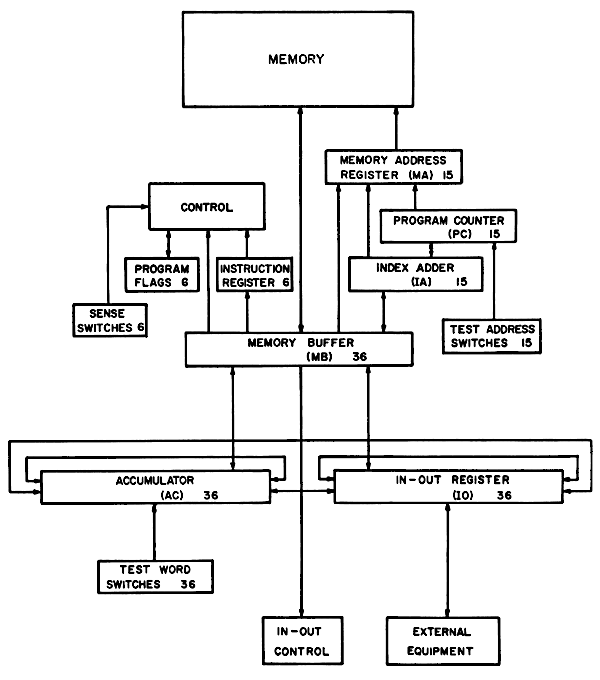
SYSTEM BLOCK DIAGRAM FIGURE 1

INSTRUCTION FORMAT FIGURE 2
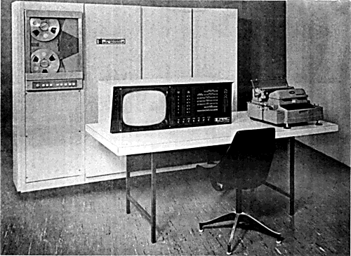
FIGURE 3
Transcriber's Notes
Figure 4 is referred to in the text, but a copy could not be located. C (X) and C(X) standardized to C(X). Other changes from the original text are highlighted.