Chapter VIII · IGNITION SYSTEMS
Reading edition
(73) Principles of Ignition.
It is the purpose of the ignition system to raise a small portion of the mixture to the combustion temperature, or the temperature at which the air and fuel will start to enter into chemical combination. When combustion is once started in a compressed combustible gas it will spread throughout the mass no matter how small the original portion inflamed. The rate at which the flame spreads through the combustion chamber depends upon the compression pressure, the richness of the mixture, the nature of the fuel and upon the number of points at which it is ignited.
In practice perfect ignition is seldom realized. This is due not only to the ignition system itself but to poor mixture proportions, imperfect vaporizing of the fuel, and low compression; all of which tend to a slow burning mixture with the attendant losses.
The best ignition system will be that which will cause the ignition to occur invariably at the point of highest compression and which will supply ample heat to start the process of combustion with a cold cylinder, imperfect mixtures, and low compressions. An efficient and reliable ignition system is without a doubt the most important unit in the construction of a gas engine. As ignition systems have improved and become more reliable, so has the gas engine become more widely used and appreciated, and in almost a direct proportion to these improvements.
Many ingenious ignition systems have been proposed, but only two of these have met with any degree of success in practice; i. e., electrical ignition and ignition by means of the hot tube.
Sponge platinum has the peculiar property of igniting jets of hydrogen gas, or hydrocarbons, without the aid of heat; this is due to the condensing effect of the platinum on these gases.
196It was proposed to ignite the gaseous charge of the gas engine by means of the platinum sponge (catalytic ignition) but the system proved a failure because of the clogging of the pores in the sponge by fine particles of soot.
Dr. Otto employed an open flame which was introduced into the mixture by means of a slide valve. This met with only a fair measure of success.
Cerium, Lanthum and several other rare metals cause a considerable spark when brought into contact with iron or steel. The objection to this method was the expense of the Cerium plugs which required frequent renewal.
The writer remembers a quaint attempt at firing the charge by means of a piece of flint and steel; the failure of this is obvious.
The Diesel Engine, a great success from a thermodynamic standpoint, is fired by means of the heat produced by the compression of air, the fuel being sprayed into air which is compressed to several hundred pounds pressure.
Mr. Victor Lougheed proposes ignition by means of a platinum wire rendered incandescent by a current of electricity. The plan sounds feasible, but we are still waiting to be shown.
Electric ignition is applicable to all classes of engines; in fact this system made the variable speed engine as used on automobiles, etc., a possibility, as accurate timing with the electric spark covers the range from the lowest possible speed to speeds of 4,500 revolutions per minute and over.
(74) Advance and Retard.
While the combustion of the mixture is extremely rapid under favorable conditions, there is, nevertheless, a perceptible lapse between the instant of ignition and the final pressure established by the heat of the combustion. For this reason it is necessary that ignition should be started a certain length of time before the pressure is required if we are to expect a maximum pressure at a definite point in the stroke of the piston. The amount by which the time of ignition precedes that of combustion is called the ADVANCE, and is usually given in terms of angular degrees made by the crank in traveling from the time of ignition to time of maximum pressure. Since the pressure is always required at the extreme end of the compression stroke, the degree of advance is given as the angle made by the center line of the cylinder with the center line of the crank at the instant of ignition. Should the advance 197be given as 10°, for example, it is meant that the crank is still 10° from completing the compression when ignition occurs.
Owing to variations in the richness of the mixture, and changes in the compression pressure, due to throttling the incoming charge, the rate of inflammation varies from time to time under varying loads. To keep the maximum pressure at a given point under these conditions it is necessary to vary the point of ignition to correspond with the increase or decrease of inflammation. This variation of advance to meet varying loads is approximated by the governor in some engines, and manually in others. The advance of an automobile is an example of manual ignition control. Should the point of ignition vary from the theoretical point it will result in a loss of fuel and power, and for this reason the ignition should be under at least an approximate control. A wide variation in engine speed has a very considerable effect on the ignition point as there is less time in which to burn the mixture at high piston speeds, and consequently the ignition must be further advanced to insure complete combustion at the end of the stroke. This fact is evident to those who have driven automobiles.
Should the ignition occur too early, so that combustion is complete before the piston reaches the end of the stroke, there will be a loss of power due to the tendency of the pressure to reverse the rotation of the engine. When starting an engine, over-advanced ignition will throw the crank over in the reverse direction from which it is intended to go, and will not only prevent the engine from coming up to speed but will prove dangerous to the operator.
Due to the effects of inertia and self induction in several types of ignition apparatus, a greater advance will be required than that demanded by the combustion rate of the mixture. This sluggishness of the apparatus in responding to the piston position is called ignition LAG. The total advance required to have the combustion complete at the end of the stroke is equal to the advance required by the burning speed plus the ignition lag. Since lag is principally due to inertia effects, it is much greater at high speeds than at low, and it therefore causes an additional advance at high speeds. Causing the ignition to occur before the crank reaches the upper dead center is called ADVANCED IGNITION, causing it to occur after the piston has reached the upper dead center, or when on the outward stroke, is called RETARDED IGNITION.
198Ignition is retarded when starting an engine to prevent it from taking its initial turn in the wrong direction. As the combustion takes place after the compression, with the piston moving on the working stroke, in retard, it is impossible for the pressure to force the piston in any direction but the right one. Excessively retarded ignition will cause a power loss and will also cause overheating of the cylinder and valves as the combustion is slower.
(75) Preignition.
Preignition which is in effect the same as over-advanced ignition as due to causes within the cylinder such as incandescent carbon deposits or thin sharp edges in the cylinder that have become incandescent through the heat of the successive explosions. Preignition is very objectionable since it causes heavy strains on the engine parts and causes a loss of power in the same way as over-advanced ignition. Any condition that causes the preigniting of the charge should be removed immediately.
(76) Misfiring.
The failure of the ignition apparatus to ignite every charge is called MISFIRING. This missing not only causes a waste of fuel and a loss of power but it also causes an increased strain on the engine parts because of the violence of the explosion following the missed stroke. The heavy explosion is due to the fact that the stroke following the “miss” is more thoroughly scavenged by the two admissions of the mixture than the ordinary working stroke, and consequently contains a more active charge.
(77) Hot Tube Ignition.
A combustible gas may be ignited by bringing it into contact with surface heated to, or above the ignition temperature. It is upon this principle that hot tube ignition is based.
In practice this surface is provided by the bore of a tube which is in communication with the charge in the cylinder, the outer end of the tube being closed or stopped up. Around this tube is an asbestos-lined chimney which causes the flame from the Bunsen burner to come into contact with the tube and also prevents draughts of air from chilling it.
A Bunsen burner is located near the base of the tube and maintains it at bright red heat. The gas for the burner is supplied 199from a source external to the engine. When the fuel used is gasoline, a gasoline burner is used, which is fed from a small supply tank located five or six feet above the burner.
During the admission stroke, the hot tube is filled with the non-combustible gases remaining from the previous explosion, therefore, the fresh entering gases cannot come into contact with the hot walls of the tube and cause a premature explosion, before the charge is compressed.
As the compression of the new charge proceeds, the fresh gas is forced farther and farther into the tube and at the highest point of compression it has penetrated far enough to come into contact with the hot portion. At this point the explosion occurs.
The tube being of small bore, does not allow of the burnt gases mingling with the fresh within the tube; the waste gases in the tube acting as a regulating cushion. The distance of travel of the new mixture is proportional to the compression, hence the explosion does not occur until a certain degree of compression is attained.
The length of the tube required for a given engine is a matter of experiment, as is also the location of the heated portion. High compression naturally forces the mixture farther into the tube than low, therefore the flame should come into contact with the tube at a point nearer the outer end with high compression than with a low compression.
Shortening the tube causes advanced ignition, as the mixture reaches the heated portion sooner, or earlier in the stroke, because of the decreased cushioning effect of the residue gases in the tube.
The length of tube and location of maximum heat zone should be so proportioned that combustion will take place at the highest compression. Moving flame to outer end of the tube retards ignition. Moving the flame toward the cylinder advances it.
While the hot tube is the acme of simplicity in construction, it is not the easiest thing to properly adjust, as the adjustment depends on compression, temperature of the tube, and the quality of the mixture. Any of these variables may cause improper firing.
The hot tube is rather an expensive type of ignition with high priced fuel, as the burner consumes a considerable amount of gas, and is burning continuously during the idle strokes as well as during the time of firing.
200It is practically impossible to obtain satisfactory results from a hot tube on an engine that regulates its speed by varying the mixture or compression, as engines running on a light load will not have sufficient compression to cause the mixture to come into contact with the hot surface, the engine misfiring on light loads.
The tubes are made of porcelain, nickel steel alloy, or common gas pipe, and are of various diameters and lengths.
All of these materials have their faults. Porcelain being very brittle, is liable to breakage. Gas pipe burns out and corrodes rapidly. Nickel alloy is not liable to breakage, is not so susceptible to corrosion as iron, but is far from being a permanent fixture.
Timing valves are a feature of some systems of hot tube ignition, which correct to a certain extent the irregularity of firing of the plain type of tube.
The timing valve is introduced in the passage connecting the cylinder and tube, and prevents the gas in the cylinder from coming into contact with the heated surface until ignition is desired.
The valve is operated by means of mechanism connecting it with the crank shaft. It is evident that with sufficient compression in the cylinder, the time of ignition can be obtained with certainty.
This mechanism is rather complicated, and subject to wear, and the advantage gained by the fixed point of ignition is offset by mechanical complication and consequent trouble.
The action of hot tube igniters is erratic and their use is not advisable unless under unusual conditions. The open flame used in heating the tube is a constant menace, as it is surrounded by inflammable vapors. This feature alone condemns it in the eyes of the insurance underwriters; in many places the use of the hot tube is prohibited both by the underwriters and city ordinances.
The above inherent defects of hot tubes are supplemented by breakage, “blowing,” and clogging of the tube or passage with soot and products of corrosion, each factor of which will cause misfiring.
In case of misfiring, after determining that the tube is not broken or clogged with soot or dirt, see that the engine is being supplied with the proper mixture; that you are obtaining the proper compression; and that the Bunsen burner is delivering a bright blue flame on the tube at the proper point. 201Never allow the burner to develop a yellow sooty flame. A yellow flame indicates that insufficient air is being admitted to the burner. Remember that an overheated tube is quickly destroyed, and will cause misfiring as surely as an underheated tube. Regulate the gas supply to the burner.
A small leak near the outer end of the tube will destroy the cushioning effect of the burnt gas, and hence will cause premature firing of the charge. Procure a new tube.
Many engines are provided with a sliding burner and chimney which allows of some adjustment of the flame on the tube. In cases of persistent misfiring, move the chimney one way or the other. It may improve the ignition.
(78) Electrical Ignition.
Ignition by means of an electric spark is by far the most satisfactory method as it makes accurate timing and prompt starting possible. It is the most reliable of all systems and is easily inspected and adjusted by anyone having even a rudimentary idea of electricity or the gas engine. For this reason electric ignition is used on practically all modern engines (with the exception of the Diesel types). The spark is caused by the current jumping an opening or gap in the conducting path of the current, and the ignition of the charge is obtained by placing this cap in the midst of the combustible mixture to which the spark communicates its heat.
The method of producing the spark gap, and the method by which the current is forced to jump the gap, divides the electrical ignition system into two principal classes:
(1) The MAKE AND BREAK, or LOW TENSION system.
(2) The JUMP SPARK or HIGH TENSION system.
In either system the spark is produced by the electrical friction of the current passing through the high resistance of the gas in the spark gap. The incandescent vapor in the gap formed by this increase of temperatures causes the flash that is known as the spark. The temperature of the gap depends principally upon the current flowing through it, the amount of heat developed being proportional to the square of the current.
There is of course a practical limit to the amount of current used in the ignition apparatus to produce spark heat. The limit is generally set by considerations of the life of the battery furnishing the current, expense of generating the current, and the life of the contact points between which the spark occurs.
202The heat developed by an electric current is proportional to the amount of resistance offered to its flow and the strength of the current employed. The greater the resistance, the more heat developed.
The resistance of copper wire (the usual conducting path), being very low causes little rise in temperature, but the air in the opening or break has a resistance of many thousands of times the resistance of the copper; hence the current passing across the opening spark or gap raises the air to an exceedingly high temperature.
With a comparatively heavy current flowing across the break, the temperature developed is high enough to boil or vaporize any metal in contact with the spark or flame, rendering the metallic vapors incandescent. With sufficient current, the ends of the wires which constitute the break may be melted away.
For the successful and continuous operation of the engine it is imperative that ends of the conducting path or terminals be made of a metal of a high fusing point in order to withstand the heat of the spark and also that the current be kept to as low a value as possible.
In actual construction the spark gap terminals are generally made of platinum or platino-iridium, or an alloy of high fusing point. Iron is sometimes used, but deteriorates rapidly. Nickel steel lasts longer than common iron or steel but is not as durable as platinum or its alloys.
As the temperature of the electric spark or arc is approximately 7,500° F., and the ignition temperature of an ordinary rich gas at 70 lbs. compression is 1,100° F., it is evident that the quantity of current for ignition may be kept to an exceedingly low value. High compression increases the resistance of the spark gap, and requires higher electrical pressure to force a given current across a gap of given length.
(79) Sources of Current.
The electric current that causes the ignition spark is usually generated or supplied by one of the three following methods:—
1. By the primary battery which converts the chemical energy of metal, and some corroding fluid, into electrical energy, by chemical means.
2. By the magneto or dynamo that converts mechanical work or energy into electrical energy through the method of magnetic induction.
3. By the storage or secondary battery which acts as a 203reservoir or storage tank for current that has been generated by either of the two above methods. A storage battery simply returns electrical energy that has been expended on it by an external generator. A storage battery does not really generate electricity but as it is often used as a source of current for an ignition system, we will consider it as a generator.
Current producers that convert chemical or mechanical energy into electrical energy are called primary generators, and are represented by the primary battery and dynamo. The above methods are used for generating current for either the high or low tension systems.
Electricity may also be produced by friction, but as such current is without heat value it is not used for ignition purposes. Electricity produced by friction is called static electricity.
Primary and storage batteries always deliver a direct or continuous current of electricity, that is a current which flows continually in one direction. Dynamos are usually made to furnish a direct current, but can be built to deliver either direct or alternating.
Alternating current, unlike the continuous current, changes the direction of its flow periodically; flowing first in one direction and then in the other, the flow alternating in equal periods of time.
Magnetos being a special form of dynamo can furnish either class of current, but with few exceptions are built for generating alternating current.
Either current may be used for ignition purposes for either high or low tension systems.
Alternating current has several advantages not possessed by the continuous current, when used for ignition purposes. The principal advantages are:
1. Alternating current does not transfer the electrode metal of contact points, and consequently causes less trouble with vibrators and “make” and “break” ignitors.
2. Magnetos generating alternating current are less complicated, have fewer parts to get out of order, and are cheaper to keep in repair.
3. Alternating current is not liable to burn out spark coils or overheat with an excessive voltage.
4. Alternating current generators can be used at any speed without the use of governors.
204
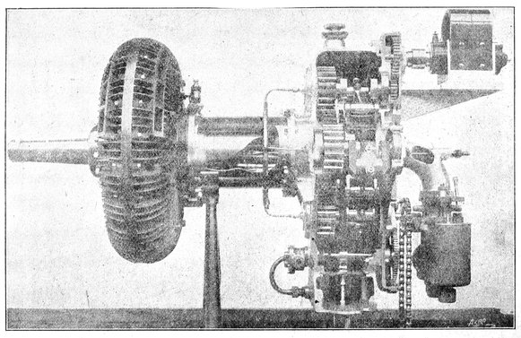
43-a. The Esselbé Rotary Aero Motor. Four Pistons are Contained in the Ring Shaped Cylinder at the Left Which are so Connected with Cranks and Gears in the Gear Box that the Pistons and the Cylinder Rotate in Opposite Directions. As the Pistons Rotate they also Oscillate Back and Forth in Regard to One Another, so that the Working and Compression Strokes are Performed. From Aero London.
When installing an ignition system give due consideration to the reliability of the source of current. The gas engine is no 205more reliable than its source of current. Failure of the current means the failure of the engine.
(80) Primary Batteries.
Current is produced in a primary battery by the chemical action of a fluid known as an ELECTROLYTE upon two dissimilar metals or solids known as the electrodes. One of the electrodes, the negative, is usually made of zinc which is more readily attacked by the electrolyte than the positive electrode. As the metal of the negative electrode is dissolved and passes into the solution during the process of current generation, the electrolyte is also exhausted. The production of current is accompanied by the liberation of hydrogen gas from the electrolyte from which it is displaced by the zinc taken into solution.
When the electrodes are immersed in the electrolyte, and the outer ends of the electrodes are connected with a wire, a current will flow from the positive electrode to the negative through the wire, and from the negative to the positive electrode through the fluid. It will be seen that to complete the circuit between the electrodes it is necessary that the current flows through the electrolyte.
Electrical energy is actually generated in the primary battery by the chemical combustion of the negative electrode in the same way that heat energy is developed by the burning of a fuel.
By connecting the binding posts of the electrodes to the two wires of the external circuit, a current will flow through the circuit as long as the electrodes remain undissolved, or until the positive electrode is covered with hydrogen gas bubbles.
The bubbles of gas tend to insulate the positive electrode from the electrolyte or fluid, thus breaking the circuit through the fluid, and stopping the flow of current. This action is known as polarization.
When a battery is polarized, the only remedy is to disconnect it from the circuit and allow it to rest or recuperate. The greater the current drawn from a battery, the more rapid the polarization, and it is evident that if the battery is to be used for long periods, polarization must be eliminated, or the current must be considerably reduced in volume. A battery that delivers a small current has a much greater capacity in ampere hours than a battery that has a higher rate of discharge. 206The greater the discharge rate the longer must be the rest periods.
A battery that is designed for continuous service, or for delivering heavy currents of long duration, is called a closed-circuit battery. Polarization is eliminated in closed circuit batteries by various methods, the usual methods being to place some substance in the electrolyte that will destroy the hydrogen film; or by packing some solid oxidizing material around the positive electrode that will absorb the hydrogen; or by making the positive electrode of some material that will destroy the hydrogen as soon as it is developed.
Batteries that are capable of being operated only for short periods, on account of polarization, are called open circuit batteries. Open circuit batteries are cheaper and more simple than closed circuit batteries. For ignition purposes, a battery is made that is a compromise between the closed and open circuit cells, this being a battery in which the polarization is only partially suppressed. As the demand for current on an ignition battery is small with comparatively long rests between contacts, the compromise battery answers the purpose and is fairly cheap.
All primary batteries are in reality wet batteries, for the reason that it would be impossible to cause a chemical reaction and a current with a dry electrolyte. The action of dry and wet batteries is identical.
There are many types of wet battery in use for various purposes, but few of them are adapted for gas engine ignition because of a tendency to polarize or because of the cost of maintenance.
All wet batteries are not suitable for portable or automobile engines because of the slopping of the liquid electrolyte and the danger of breaking the containing jars. Their weight and bulk is also a drawback.
If the electrolyte or the electrodes be made of impure material local currents will be generated. These currents decrease the life of the cell without producing any useful current in the ignition circuit. Due to the deteriorating effects of the local currents, batteries standing idle for several months will often be found to be completely discharged and worthless without having done any useful work. In the better grade of cells this loss is reduced to a minimum.
A type of wet battery using a solution of caustic soda for an electrolyte, and having zinc and copper oxide electrodes, is 207extensively used for stationary ignition purposes, and is the most satisfactory type of wet cell for continuous work with this class of engine. The caustic soda battery is of the CLOSED circuit type, and is capable of furnishing a strong uniform current without danger of polarization.
The hydrogen bubbles which cause polarization are oxidized or eliminated by the copper oxide electrode as soon as they are formed. The hydrogen combines with the oxygen of the copper oxide forming water.
The copper oxide is gradually reduced to metallic copper by the reaction with the hydrogen, and in the course of time requires renewal. The copper oxide element is rather expensive and cannot be obtained as readily as the electrodes used in other cells.
It will be noted that both electrodes are consumed in the caustic battery, the consumption of the zinc furnishing the current, and the reducing of the oxide furnishing the chemical energy for depolarizing the cell.
(81) Dry Batteries.
Dry batteries are by far, the most convenient and economical form of primary battery to use, for there is no fluid to slop and leak, the first cost is low, the output is large for the weight, and last but not least, the cell can be thrown away when exhausted without great monetary loss. This does away with the expense and annoyance of changing wet cells, a factor that will be appreciated by those that are far from a source of chemical supplies. Since the advent of the automobile the use of dry cells has extended so that they may be obtained in almost any country town or village.
While the cell is not dry, strictly speaking, the solution is held in such a way that it cannot slop around in the cell nor leak out of the seal. The only fault of a dry cell is its tendency to deteriorate with age because of the constant contact of the electrolyte with the electrodes.
The negative electrode of the dry cell (zinc) is in the form of a cup which serves as a containing vessel for the electrolyte and the depolarizer.
The electrolyte is usually composed of a solution of ammonium chloride, with a small percentage of zinc sulphate, this fluid being held by some absorbent material such as blotting paper, or paper pulp.
The electrolyte is applied to the electrodes by means of the 208saturated blotting paper, which is also used to line the zinc container, thus providing insulation between the electrodes.
A rod of solid carbon which forms the positive electrode is placed in the center of the container, and the space between the rod and the zinc is packed solidly with granulated carbon, the blotting paper lining preventing contact of the zinc with the carbon.
Pulverized manganese dioxide is mixed with the granulated carbon for a depolarizer.
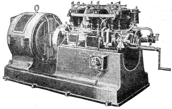
Brookes Four Cylinder Gasoline Engine Direct Connected to Dynamo.
After the zinc container is filled with the electrolyte and pulverized carbon, the top of the container is closed hermetically by means of sealing wax. Granulated carbon is used for it presents a large surface to the electrolyte, reduces the internal resistance of the cell, and therefore increases the current output of the battery.
As soon as the battery starts generating current, polarization begins, with the liberation of hydrogen gas. If the cell is discharged at a high rate, the manganese dioxide will be unable to absorb all of the gas, and consequently pressure will be erected within the cell. The greater the rate of discharge, the greater will be the amount of hydrogen set free, and the higher the pressure.
If a short circuit exists for any length of time, the pressure of the excess hydrogen will speedily ruin it, as the cell will 209puff up, or even burst under the pressure. If the rate of discharge be kept so low that all of the gas will be absorbed by the manganese, as soon as generated, the cell will furnish a steady current until the elements of the cell or the electrolyte are exhausted.
The steady current limit, or non-polarizing limit is about one-half ampere and if long life of the cell is expected, the current drain should be less than this amount. A good spark coil will develop a satisfactory spark on a quarter to one-half ampere, so that the demand of a good coil is well within the safe limits of battery capacity. The voltage of the average dry cell when in good condition is 1.5 volts on open circuit. When the cell is old or exhausted, the voltage falls rapidly when any demand for current is made on the cell, and the voltage also varies with the rate of current flow, the voltage decreasing with an increase of current.
As there is not much difference in voltage between a new and old cell when on open circuit, it will be seen that the ammeter giving the current output will give a more accurate determination of the condition of the battery. The voltage is independent of the size of cell.
The battery showing the greatest amperage is not necessarily the best for general use, as cells having an unusually high current capacity are generally short lived. The strong electrolyte used in high ampere batteries causes them to burn out or deteriorate rapidly when not in use.
Under ordinary conditions, a correctly proportioned No. 6 ignition cell should show a current of from fifteen to twenty amperes on short circuit when the cell is new, although higher results may be obtained safely with some makes of cells.
While the voltage is the same for all sizes of batteries, and depends on the material used in the construction, the amperes increase with the size of the cell, and the area of the electrodes.
If a cell does not show more than ten amperes on short circuit, it should be thrown out and another substituted for it, as the cell is liable to go out of commission at any minute when reaching this point of exhaustion.
A small battery testing voltmeter or ammeter should be in the kit of every gas engine operator using a battery for ignition, as the exact condition of a vital part of the power plant can be determined quickly and with accuracy. For dry batteries an ammeter is preferable; for storage batteries a voltmeter must be used.
210When buying dry batteries insist on having new, fresh cells, as any battery depreciates in value with age. Never take a cell without testing it, as it is the practice of dealers to work off their old stock on unsuspecting customers. Examine the battery closely for the makers’ dates, and if the battery is several months old, it is probable that the electrolyte is dried up or that the electrodes are wasted through long continued local action. As heat stimulates chemical action in the cell, they should be stored in a cool place to retard the wasting action as much as possible. Under all conditions, the cell should be kept dry, since the moisture that is deposited on the cell forms a closed circuit for the current which soon exhausts the battery. Cold retards chemical action in the cell and consequently reduces the output in zero weather to such an extent that starting is frequently impossible.
Multiple cylinder engines exhaust a battery quicker than those with a single cylinder, as there are more current impulses in a given time and consequently more current is used. A battery may be compared with a bottle that holds a certain quantity of fluid. If the water is allowed to drip out slowly it will last for a long time, but if allowed to flow in a continuous stream will soon be exhausted.
With badly designed or poorly adjusted spark coil, the demand on the batteries is greater than with one that is in proper condition. An engine that runs continuously exhausts a battery faster than one that is run at long intervals. Always open the battery switch when the engine is to be idle for any length of time, as the engine may have stopped with the igniter in contact, allowing the battery to expend its energy uselessly.
Test batteries immediately after a run, as the batteries will recover after standing a while, and will show a fictitious value.
A weak, partially exhausted battery will cause a poor spark that will result in misfiring or a loss of power. It is poor economy to attempt running an engine on a weak battery. An engine may run on a weak battery for a short time, and then gradually decrease in speed until it comes to a full stop. Misfiring is generally in evidence as the engine dies down. In case of an emergency, weak batteries may be made to run an engine of an automobile or boat to its destination, by stopping the engine frequently and allowing the batteries to recuperate during the idle periods. A battery that is temporarily weakened by hard service or by a temporary short circuit will usually revive or partially recover its strength if allowed to “rest” for 211a short time until the hydrogen is absorbed by the depolarizing material. The life of a dry cell can be extended for a few hours by punching a hole in the sealing wax on the top of the battery, and pouring water, or a solution of water and sal-ammoniac into the cell. This will reduce the internal resistance and increase the current. The batteries will run under these conditions for a short time only, and new cells should be procured at the earliest possible moment. No old cell can be made as good as new by any method. Never drop the cells on the floor nor subject them to hard usage mechanically, for if the active material is loosened, the current output will be reduced. A short circuit through a closed switch with the engine stopped or a loose dangling wire will put the cells beyond repair.
If the binding screw on the carbon electrode does not make good contact with the carbon, tighten it to decrease the resistance. Fasten the connecting wires firmly under the binding screws and keep the connections clean.
In the absence of an ammeter, a rough estimate of the condition of the cell may be made by fastening a short wire tightly in the zinc binding post, and touching the carbon surface lightly and intermittently with the free end of the wire. When contact is made with the free end of the wire, a small puff of smoke will arise and a red spark will be seen if the cell is in good condition.
Sometimes the contact made on the carbon will produce only a small black ring on the surface of the electrode. This indicates a battery that is nearly exhausted, and one which is good for only a few more hours of service.
When a number of cells are connected together in such a way that they collectively form a single source of current, the group is called a battery, and the resulting voltage and amperes of the group depends on the way in which the cells are interconnected.
It is possible to connect the cells of a battery in such a way that total voltage of the group or battery is equal to the sum of the voltages of the individual cells. A battery connected in this manner is said to be connected in series. While the voltage of a battery is increased, by series connection, the number of amperes is the same as that given by a single cell, the same current flowing through the set.
(82) Series and Multiple Connections.
Fig. 86 shows the cells connected in series, the carbon terminal of one cell being connected to the zinc terminal of the 212second. The carbon of the second cell is connected to the zinc of the third, and so on throughout the series, the two remaining terminals of the battery being connected with the ignition circuit. The number of watts or power developed by the group is equal to the sum of the outputs of the separate cells. If the voltage of each cell shown in diagram is 1.5 volts, the total voltage of the group of five cells will be 1.5 × 5 = 7.5 volts, and if the current of a single cell is 15 amperes, the current output of the group will be 15 amperes, or the same as that of a single cell. Almost all ignition apparatus now on the market requires six volts for its operation, so with cells having a voltage of 1.5 volts such apparatus would call for four cells in series, as 6 ÷ 1.5 = 4.
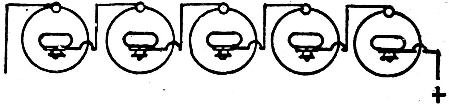
Fig. 86. Five Cells in Series.
Owing to the increase of internal resistance caused by series connections it is usual to add one more cell than is theoretically required, making a group of five cells to supply the six volts required. A large number of cells will give a hotter spark than a smaller, but the excessive current causes the contact points of the igniter or vibrator to burn off rapidly and also hastens the destruction of the cells themselves.
Batteries connected in such a way that the total amperes of the group is increased without increased voltage are said to be connected in multiple or parallel. When batteries are connected in multiple, the total current in amperes is equal to the sum of the amperes delivered by the separate cells; and, while the current in amperes is increased by multiple connection, the voltage of the group remains equal to that of a single cell.
If each cell connected in multiple has an electromotive force of 1.5 volts, and can deliver 15 amperes, the total current delivered by this system of connection will be 15 × 5 = 75 amperes with five cells, and the electromotive force will be 1.5 volts as in the case of the single cell. By connecting batteries in multiple, the resistance is reduced, allowing a maximum flow of current. The demand on the individual cells is reduced by multiple 213connection, as each cell only furnishes a small part of the total current. The greater the number of cells, the less will be the current required per cell, with a given total current. As the life of a battery depends entirely upon the rate at which it is discharged, it is necessary, for economical reasons, to keep the current per cell as small as possible, therefore the multiple system would prove of value as it reduces the load to the smallest possible limit. Enough cells should be placed in multiple to reduce the current to less than a quarter of an ampere per cell. The cells shown will not have sufficient voltage to operate ordinary ignition apparatus requiring a potential of six volts, hence the multiple system must be modified in order to have an increased voltage, and at the same time secure the advantages of multiple connections.
(83) Multiple-Series Connections.
A compromise is affected by the multiple series system of connections in which are combined the advantages of both the series and multiple systems of connection.
This arrangement allows sufficient voltage to operate 6 volt apparatus and at the same time reduces the rate of discharge on the individual cells. The series-multiple battery shown in the diagram 88 consists of four groups of batteries connected in multiple, each group of which consists of five cells that are connected in series. The current and voltage in the various branches is shown in the diagram. The series-multiple system is adapted for use with multiple cylinder engines, as engines with more than one cylinder cause a severe drain on the ignition system. Arranging the series groups in parallel increases the life and efficiency of the cells. If an efficient coil is used, the drain of a single cylinder is not too great to be met with a single set of series cells. If possible the set should be provided with a duplicate, so that the load could be transferred from one set to the other at proper intervals by means of a double throw switch.
With a single set of batteries in series the working life of the cells will be approximately twenty hours under ordinary conditions. With four groups of four cells in series, the life of the cell will be approximately 160 hours, or eight times the life of the single set under similar conditions.
While the cost of the cells will be only four times that of the single set, it will be seen that the cost of battery upkeep is halved by reducing the demand on the cells.
214Sometimes duplicate sets of series multiple connected batteries are used for heavy duty engines, the engine running on one set for a while and then on the other, allowing the first set to thoroughly recuperate before it is again thrown in service, by means of the double throw switch.
When batteries are multiple or series-multiple connected they should be of the same size and make and of the same voltage. If the cells are of different voltages useless local currents will circulate among the cross-connections, shortening the life of the battery and reducing the output.
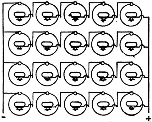
Fig. 88. Cells in Multiple Series.
In connecting a dry cell use a good grade of rubber insulated wire, preferably wire with a stranded conductor, as it is less liable to break or loosen at the binding screw of the battery. Carefully remove the insulation from the end of the wire that is to be fastened under the binding screw of the battery. Scrape it until it is bright and perfectly free from dirt before fastening it in the battery terminal. Never allow a dirty or corroded connection or a loose wire to exist. An open battery circuit or loose connection will stop engine suddenly, or will prevent starting.
The battery connections should be screwed down tight with the pliers, care being taken that the screws are not broken by 215the tightening process. See that frayed ends of the wire do not project beyond the binding screw to which they are connected and make contact with other cells or metal objects. Be sure that no insulation gets between the contact braces of the binding screw.
(84) Operation of Dry Cells.
The following hints should be observed to obtain the best results with dry cells.
(1) Never remove the paper jackets from the cells.
(2) Never lay tools or other metallic objects on top of the cells for this will cause a “short” that will quickly exhaust them.
(3) Do not connect old and new cells together, especially with the multiple-series system of connections, for the old cells will limit the output of the new, or else will cause cross-currents that will exhaust all of them.
(4) When trouble develops in the battery, test each cell separately and remove the faulty cells. Do not reject all of the battery because of one or two dead cells.
(5) Place the cells in a wooden box that will protect them from dirt or moisture, and if possible divide the box off into pigeon holes with a cell in each hole. For the best protection against moisture, the box should be boiled in paraffine.
(6) Provide a battery switch on the box that will cut both leads from the cells completely out of circuit when the engine is stopped.
(7) Never place a dry cell in a box that has contained storage cells unless the box has been thoroughly washed out, for the residual acid of the battery will destroy the zinc elements.
(8) Make all connections firmly with well insulated wire and take care that the wire does not make contact with any part of the battery except that to which it is connected.
(9) Keep the battery dry.
(85) Storage Batteries.
The purpose of the storage battery is to store or accumulate the current generated by a dynamo until so that the current will be available when the dynamo is not running. A storage cell does not “store” current in the same way that water is held in a tank, but returns the energy expended on it through the chemical changes caused in the cell by the current.
When the charging current passes through the storage battery chemical changes are produced in the electrodes and 216electrolyte, and the energy expended on the cell is in the form of latent chemical energy, in which state it remains until the electrodes are connected with one another by a wire or some other conducting medium. When the electrodes are connected through an external circuit, the electrolyte acts on the electrodes causing them to assume their original composition. As they pass into their previous chemical condition the latent chemical energy is converted into electrical energy. The current thus produced may be used in the same way as in a primary cell.
When discharging, the action of a storage battery is similar to that of a primary battery, the current being produced by the action of a fluid on two dissimilar electrodes. Instead of supplying new elements when the battery is discharged, as in the case of the primary cell, the elements are brought back to their original state by passing a current through the cell in the opposite direction to that of the discharge.
There are several combinations of materials which may be used in the making of storage battery electrodes and electrolytes, but with the exception of the lead sulphuric battery and the new Edison battery none have proven a commercial success.
The most common type of storage or secondary cell is the lead-sulphuric type in which the electrolyte is dilute sulphuric acid and the electrodes are lead plates, covered with a chemical composition known as the active material. These plates usually consist of a lead grid, or lattice frame in the pockets of which is pasted the active material. The pockets or lattice bars of the plates are for the purpose of supporting the active material which is of a weak and spongy nature. The active material on the positive plate is usually litharge, while that on the negative plate is red lead.
After charging, the active material on the positive plate is changed to lead peroxide by the action of the current, and the active material on the negative plate is changed into spongy metallic peroxide. The composition of the active material on the plates determines the direction of flow of the discharge, or secondary current. The current flows from the positive plate to the negative through the external circuit.
When fully charged, and in good condition, the positive and negative plates may be readily distinguished by their colors, the positive plate being a dark brown or chocolate color, and the negative a slate or grey color.
217The positive active material is hard, while the negative may be easily cut into by the finger nail. The density of the material changes slightly with the charge, as the material expands during the discharge.
The problem of holding the active material securely to the plates during expansion and contraction has been a hard one to solve, each manufacturer having some favorite form of grid or material plug to which he pins his faith. While great improvements have been made in this direction, it is certain that we have not yet reached perfection. Loose active material will cause short circuits and will reduce the output of the cell; loose active material frequently ruins a cell.
The current capacity of a storage battery depends on the area of the plates or electrodes, and in order to increase the capacity of a battery, and consequently the area, it is usual to use a number of plates connected in parallel. A number of small plates of a given area are to be preferred to two large plates of the same area, as the battery will be of a more convenient size.
Customarily there is one more negative plate than positive, so that the extreme end plates in a cell are negative, as the positive and negative plates alternate with each other when assembled.
An ignition battery usually consists of two negative plates and one positive. Cells used for power purposes have as high as sixty plates.
A single cell of storage battery should show about two volts when fairly well charged. If more than two volts are desired more cells should be connected in series. The total voltage will be equal to the number of cells, in series, multiplied by the voltage per cell. The voltage per cell should never be allowed to drop below 1.7 volts, as the cell is likely to be destroyed when operated with a low voltage. Recharge as soon as the voltage drops to 1.8 volts.
The ordinary six volt ignition battery consists of three separate cells connected in series, which are encased in one protecting box.
The plates are prevented from touching each other within the cell by means of a perforated sheet of hard rubber that is inserted in the space between the plates. The perforations allow the liquid to circulate between the plates.
The storage battery is furnished as standard equipment with several well known gas engine builders, and its use is advocated by nearly all. When used in connection with a low tension 218direct current magneto two independent sources of current are at hand, either of which will ignite the engine in an emergency.
With the magneto-storage battery combination, it is possible to obtain a few small lights at any time, whether the engine is running or not, and the engine is always ready to start on the first “over” with the storage battery and a good mixture.
If a magneto is not used, difficulty is sometimes experienced in obtaining a suitable source of charging current, as many localities do not possess direct current plants. Batteries may be charged from the direct current exciter in an alternating current station, or may be charged by an alternating current rectifier such as is used by automobile garages.
The principal objections to the storage cell are: inconvenience of charging; sulphating of cell when standing without a charge; ease with which the cell is ruined by short circuits; the damage caused by the spilling of the electrolyte; and the fact that the cell gives no warning of failing or discharged condition.
Since the composition of the plates depends on the direction in which the current flows through the cell, it is obvious, that an alternating current which periodically changes its direction of flow will first charge the plates and then discharge them alternately. The result of an attempt at charging with alternating current would be that the plates would be in the same or a worse condition in a short space of time than they were at the beginning. In charging a storage cell care should be taken to determine the character of the current, especially when the cell is to be charged from a magneto. When under charge, the cell is connected to the charging circuit in such a way that the current flows backwards through the cell or in a direction opposite to that when the cell is discharging.
(86) Care of the Storage Cell.
The storage battery should never be left in an uncharged condition with the acid electrolyte in the cell, for the solution will quickly attack the uncharged plates and combine with them to form lead sulphate. As lead sulphate has a high electrical resistance and is insoluble in the electrolyte the sulphate coating will reduce the output or if present in excess, ruin the cell. The sulphate appears as a white coating on the surface of the plates. The only remedy for this condition at the hands of the average engine operator is a prolonged charge, or over charge, at a slow rate. There are several chemical processes but they are too complicated for the average man.
219As sediment collects on the bottom of the battery jars, and is liable to cause a short circuit, the plates should be held about half an inch from the bottom of the jar. Care should be taken that the cells of the stationary type of battery are kept dry and clean. Do not allow dirt to drop into the solution as it is liable to destroy the cell.
A volt meter should be used to determine the condition of the battery, and should be used frequently. An ammeter should never be used on a storage battery, as it is of very low resistance, and would probably cause a rush of current that would destroy both the battery and the instrument.
Never short circuit a storage battery, even for an instant, as excessive current will cause the plates to buckle, or will loosen the active material on the plates.
The plates are immersed in the electrolyte, which should cover the entire plate or active surface. If the solution does not cover the plate, the capacity of the cell will be reduced. Plates that are partially covered with solution deteriorate rapidly from “sulphating.” This is caused by the air and acid acting on the damp inactive portion of the plate.
Usually the electrolyte consists of a dilute solution of sulphuric acid and water, but in some ignition cells the solution is “solidified” by some substance to about the consistency of table jelly. The object of this thickened solution is to prevent the solution from slopping and leaking when the battery is being transported.
The solution used in a storage battery is exceedingly corrosive in its action, and if spilled on metal or wood will destroy it immediately. Care should be taken in handling the electrolyte.
A cell should never be discharged below 1.7 volts for below this point, the plates are likely sulphate. When the solution is replaced by fresh, or water is added for the purpose of restoring the electrolyte to its original level, use only distilled water, free from metallic salts and suspended matter.
Many people “test” their cells by snapping a wire across the terminals to “see if there is a good spark.” Nothing could be more injurious to the battery, and as this test indicates nothing, the practice should be discontinued. Make all your tests either with a hydrometer or a voltmeter, the latter is preferable in the average case.
The electrolyte is a solution containing approximately 10% of chemically pure sulphuric acid and 90% of distilled water. The specific gravity of the fluid should be from 1,210 to 1,212 220in all cases. A standard battery hydrometer should be used by all storage battery users to ascertain the exact density of the solution as the specific gravity is a direct index to the condition of the cell. A gasoline hydrometer is useless for a storage battery.
When mixing the electrolyte it should be placed in a glass or porcelain jar, and the process should never be performed in the battery jar in the presence of the plates. The solution is very active chemically and should not be brought into contact with metallic or organic substances because of the danger of contaminating the fluid. The acid should always be poured into the water in a thin stream while the mixture is being stirred with a glass or porcelain rod. Pouring the water into the acid is likely to produce an explosion and should therefore be carefully avoided.
As the acid heats the water during the mixing the hydrometer reading should not be taken until the heat caused by the first addition of acid has been reduced to that of the room. Taking a reading with a hot solution will give inaccurate results, unless, of course, the reading is reduced to normal by the method described in a previous chapter. When the reading has been taken and found to be correct and the solution has been reduced to the temperature of the room, the electrolyte may be poured into the cell through the filler openings in the top of the cell. Pour into each cell sufficient fluid to cover the plates but avoid filling the cell to the top, or flooding it.
At the end of the charging time given by the maker, withdraw a sample of the electrolyte by means of a syringe and test the specific gravity. This should not be over 1,290 for a fully charged cell, and if the solution exceeds this amount, pure water should be added until the proper point is reached. Always correct the specific gravity in this way every time the battery is charged as evaporation and internal chemical changes cause the density to change from time to time. The voltage of a good storage battery will be about 2.1 volts when fully charged. Overcharging is wasteful and finally destroys the cell, the effects being similar to those caused by excessive discharges, that is, buckled plates and loosened active material. Overcharging a sulphated battery may cure the trouble, a little overcharging at intervals being better than a long continued overcharge.
An increase in the specific gravity of the electrolyte of from 22130 to 50 degrees, with a corresponding rise of voltage, shows that the cell is fully charged.
After the charging is completed remove all of the solution spilled on the battery, preferably by washing, and wipe bone dry. If the solution is higher in the air, remove the excess with the syringe.
(87) Make and Break System (Low Tension).
When a circuit carrying a current is opened or broken at any place in its length, an electric spark will occur at the point at which the wires or contacts are separated. This is due to what might be termed the “momentum” of the current which causes it to persist in its course even to the extent of jumping over a short distance of the highly resistant air in the gap. The size and heat of the spark may be increased by placing a coil of copper wire in series with the circuit that has an iron core in the center of the turns. This coil increases the tendency of the current to jump the gap, or in other words increases the momentum of the circuit.
Each separation of the terminals of the circuit causes but a single spark, so that in order to obtain another the terminals must be again brought into contact and the current reestablished in the circuit before the circuit is again opened. Thus the function of the make and break igniter is to alternately make and break the circuit in the presence of the combustible mixture. To obtain the greatest spark and most certain ignition, the contact points should be opened with the greatest possible speed, an action that is accomplished in the actual engine by springs and triggers.
A typical cylindrical make and break coil consisting of an iron wire core surrounded by a coarse copper wire core is shown by Fig. 91. At one end of the coil will be seen the two terminal screws by which it is connected with the circuit. Another make and break coil is shown by Fig. 92, which has the same type of winding, but differs in having the core wire coil extended beyond the winding and heads. By closely examining the cut, the iron wires will be seen in the projecting core tube at the left end of the coil. A flat base is also provided for fastening it to a stationary foundation.
A typical make and break igniter is shown by Fig. 93, together with the usual circuit consisting of a primary coil and battery. In this figure, A and C are the two electrodes provided with platinum contact points N and O respectively. The 222electrode A is stationary and is insulated from the iron casing K by the insulating washer H, and the insulating bushing or tube I. The electrode C is oscillated intermittently by the engine through its shaft E, and the trigger G, the springs S serving to snap the platinum contact O away from N at the proper moment. This electrode (C) is in electrical connection with the shell K, and the engine frame at all times, and is provided with a brass bushing F for a bearing surface. The outer containing casing K is bolted to the combustion chamber of the engine by the bolts LL, so that the electrodes A and C project into the combustion chamber.
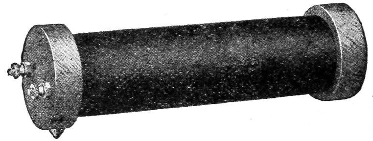
Fig. 91. Kingston Cylindrical Make and Break Coil.
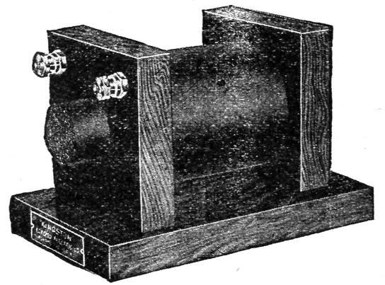
Fig. 92. Kingston Make and Break Coil. Short Type.
Current from the battery R passes through the coil winding P to the coil terminal U from which it passes from V to the igniter binding post J. From J it flows along the rod D to the stationary electrode A. Since the rod D is surrounded by the insulating washers and tube H, T and I, the current cannot escape directly to the casing K. With the two platinum points N and O in contact, the current flows through C to the shell K from which point it flows back to the battery R through the conducting path V, completing the circuit. The greater 223portion of the path V consists of the engine frame. When the electrode is moved in the direction of arrow B, the current is opened and a spark occurs at the point of separation M, in contact with the gas in the combustion chamber. The electrode C being connected with the engine frame is said to be “grounded.” If the stationary electrode A were not insulated from the casting K, the current would pass directly from the terminal J back to the battery R without passing through the contact points at all, and consequently no spark would be produced on the separation of the points.
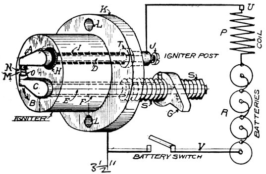
Fig. 93. Diagram of Igniter and Connections.
A push rod which is actuated by a cam on the engine, engages with the trigger G, and causes the spark to occur when the piston is on the end of the compression stroke. In nearly all engines, the relation between the time of the spark and the piston position can be regulated to suit the requirements for advance and retard. This adjustment is necessary in order that the spark may be varied to meet the difference between the starting and running requirements.
While the ignition should be considerably advanced while running, it is necessary to retard it when starting, as the engine is liable to “kick back” with an advanced spark.
This advance and retard device should be accessible while the engine is running, and the operator should be able to control 224the point of ignition at all times. Many men have been seriously injured by the lack of this device or by neglecting to use it.
The contact points make contact only for a short time before the spark is required in order to reduce the amount of current to the minimum, and therefore increase the life of the batteries.
The duration of the “make” or contact should be as short as possible. Prolonged contact weakens the batteries and causes them to run down rapidly. For the same reason the electrodes should remain separated until the make is actually required.
A certain period of contact is necessary, however, to allow the spark coil to “build up,” but with a properly designed coil the time required is very short.
Some engines provide a device that cuts out the ignition current altogether during the idle strokes. This adds materially to the life of the batteries.
The igniter should be located near the inlet valve, as the cold incoming gases tend to keep it cool and clean, besides insuring the presence of combustible gas around the igniter electrodes. Improper placing of the igniter will greatly reduce the efficiency of the engine. Avoid placing the igniter in a pocket, or in the path of the exhaust gases.
The make and break ignition system has many good features, but cannot successfully be applied to engines running over 500 revolutions per minute, nor can it be applied to engines of less than 3 H. P. as the parts would be too small and delicate to be durable.
The make and break igniter produces the largest and “hottest” spark of any type of ignition, and is especially desirable for large or slow running engines. Being operated at a low voltage, it is not as easily affected by moisture, poor insulation, or dirt as the high tension or jump spark system, nor is it liable to give the operator such a violent “shock.”
Engines governing by the “hit and miss” system have a device that cuts out the current during the “missed” power strokes. This effects a considerable saving in battery current, especially on light loads when the engine misses a great number of strokes.
While possessing many points of merit, the make and break system is open to several serious objections:
1. Due to the high combustion temperature there is excessive wear of the working parts in the cylinder, this wear causes a change in the ignition timing.
2252. The low voltage used in the make and break system calls for perfect contact of the electrodes in the cylinder. This contact is often interfered with or entirely prevented by the accumulation of carbonized oil and soot deposited on the surfaces.
3. The wear of the operating spindle or shaft, which passes through the cylinder wall causes leakage, which in turn causes a loss of compression in the cylinder.
4. The wear of the external operating mechanism produces a change in the timing. The edge of the fingers, wiper blades, etc., tend to cause an advance in the ignition as a general rule, with the attendant danger of broken crank shafts.
5. The system is mechanically complicated, correct operation calling for constant care as to adjustment.
All ignition apparatus wears in the course of time and changes the timing of the engine. The electrodes and push-rods wear and require readjustment. Generally the tendency of worn parts is to advance the ignition. This change in timing occurs so gradually that the operator does not notice it until the engine begins to pound, or until the efficiency has been considerably reduced.
When the engine is new it is well to mark the ignition mechanism in such a way that the relative positions of the crank and igniter will be shown at the time when the igniter trips. It will then be possible for the operator to refer to the marks at any time to tell whether his ignition is occurring at the proper time. Always mark the half-time gears when taking the engine apart for the difference of one tooth when reassembling will be sufficient to throw the engine out of time.
The usual method of marking the gears, is to center punch, or scratch one tooth on the small gear, and then mark the two teeth of the large gear that lie on either side of it. With these marks it is possible to replace the gears in their original and proper positions.
The igniter should trip, causing the electrodes to separate just before the end of the compression stroke is reached, or just before the crank reaches the inner dead center. The distance lacking the exact dead center represents the instant of time between the time of ignition and the actual pressure established by the combustion.
As most engines have the ignition considerably retarded when starting, the igniter will trip later with the lever in the “start” position than when in the “running” position. Never fail to retard spark when starting nor forget to advance it when engine is up to speed.
226The actual advance given to an engine depends on the character of the fuel and on the speed.
An engine is said to have an advance of 10°, if the crank lacks 10° of having made the inner dead center at the time of ignition.
The most economical point of ignition is easily determined when the engine is running on a steady load, by varying the point of ignition and noting the position assumed by the governor.
(88) Operation of the Make and Break Igniter.
To keep the igniter in order, and to obtain the best results with the least trouble, the following hints should be observed:
(1) Clean the igniter frequently, and remove all deposits of oil and carbon. For cleaning, the igniter must be removed from the cylinder, care being taken to avoid injury to the packing or gasket. Graphite dusted on the gasket will prevent it from sticking to either the igniter or cylinder.
(2) If the contact points are rough, pitted, or covered with a carbon deposit, the scale should be removed, and the points smoothed down with a fine file, taking care that the two faces are filed parallel with one another.
(3) Insulating washers and tubes should be removed and washed in gasoline. The hole through which the igniter rod passes should be scraped free from any deposit for much trouble can be caused by a tight working shaft.
(4) Examine the hole or bushing through which operating spindle passes, for wear. A worn spindle or bushing may cause a serious loss of compression; replace worn bushing at once.
See that the insulation of the stationary electrode is not broken. If it is injured in the slightest degree, replace it with new.
(5) Often the sparking points may be cleaned temporarily without removing the igniter from the cylinder by pulling upon the outside finger or trigger until the points come together, and then pushing in towards the cylinder several times on the movable electrode, which slides them one on the other, scraping off the deposit. This method is only a make shift.
(6) After removing igniter, replace all wires, screwing them firmly into place. The ends of wires and connecting screws should be perfectly clean when the connection is made; to insure perfect contact, the surfaces should be scraped or sand-papered until bright and shining. See that no foreign matter of any 227kind gets between the wires and the metal of the binding screws. Wherever possible connections should be soldered.
(7) A small coil of the wire should be made at the point of connection; i. e., the wire should be a trifle longer than necessary to reach the binding screw, the excess wire being coiled up on a pencil. This coil allows of removing igniter, allows for broken wire ends and reduces the tendency to loosen the connection.
(8) Ground wires, or wires connected with the frame of the engine should receive careful attention. They are generally fastened under some screw or bolt on the engine which may become loose or fail to make contact, thus opening the entire circuit and causing the engine to stop. The ground wires are generally connected in inaccessible places, and require all the more attention for this reason.
(9) For the primary of low tension wiring, use only the best grade of stranded rubber covered wire. A special wire for ignition purposes is on the market. It is rather expensive but is just the thing for the service.
Never use cotton covered or waxed wire. This covering affords absolutely no protection against moisture or abrasion.
(10) As the voltage of a primary circuit, or circuit for make and break is very low, and the current comparatively high, it is well to have the copper as large as possible. It should never be less than number 14 gauge. Don’t use solid wire if you can obtain stranded conductor. (Stranded wire is made up of a number of fine wires which are twisted into a cable or rope of the desired size.)
(11) Oil destroys rubber insulation and should be kept off the wiring. Try to locate the conductors so that they will be out of range of oil thrown by the moving parts.
(89) Jump Spark System (High Tension System).
Due to its simplicity and the light weight of its moving parts, the high tension ignition system is applied to practically all small, high speed engines running 500 R.P.M. or over. The high tension system is also desirable from the fact that it has no moving parts in the cylinder of the engine.
The principal objection to the high tension system is the ease with which the high voltage current leaks or short circuits, moisture being fatal to the operation of a jump spark engine.
Instead of producing the spark by breaking the circuit of a low tension current, the spark is produced by increasing the voltage 228to such a point that the current will jump directly across a fixed gap. To cause the current to jump through the air requires an extremely high voltage, and as the battery current is very low it is necessary to introduce a device known as a “transformer” to stop the current up to the required tension. In addition to the voltage required at atmospheric pressure (about 50,000 volt per inch of spark) we must also furnish sufficient pressure to overcome the increased resistance due to the compression in the cylinder.
Unlike the spark coil used on the low tension make and break system, the induction coil or transformer coil has two separate and distinct coils, that are thoroughly insulated from each other. One coil has a few turns of heavy copper wire which is called the primary. The other consists of many thousands of turns of very fine copper wire, and is called the secondary. Both coils are wound around a bundle of soft iron wire called the core, from which they are carefully insulated. When a battery or magneto current flows through the primary coil, the core is magnetized, and throws its magnetic influence through the turns of the secondary coil.
In Fig. 94 the primary coil and the low tension battery and magneto circuit are represented by heavy lines. The secondary coil, and high tension circuit are represented by light lines.
In order to obtain a continuous discharge of sparks it is necessary to make and break the current in the primary coil very rapidly. This is done by means of the interrupter or vibrator, which is indicated in the diagram by V. The interrupter consists ordinarily of a spring A on which is fastened a soft iron disc D and a platinum contact point B. When the core is magnetized it attracts the iron disc D which is pulled toward the core, bending the spring A and breaking the contact between the platinum point B and C. When the contact points are separated, and the current broken, the core loses its magnetism, and the spring assumes its normal position, which brings the platinum points B and C into contact once more, and reestablishes the current through the primary. The core is again magnetized and the primary current is again broken, and so on. This make and break of the current is thus accomplished automatically, the current being broken many thousands of times per minute, the vibrator moving so fast as to cause a continuous hum.
As soon as the current starts flowing, the magnetic force spreads out through the secondary coil and threads through the 229turns of which it is composed. The instant that the current ceases, the magnetic force decreases and the turns are again threaded by the magnetic field on its return to the core.
Thus two magnetic waves are sent through the secondary coil, one when the circuit is “made,” and one when the circuit is “broken.”
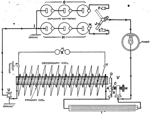
Fig. 94. Diagram of High Tension Coil.
When a magnetic wave threads or spreads through the turns of a coil of wire, a current of electricity is generated in the coil, the quantity and pressure or voltage of which is proportional 230to the intensity of the magnetism, and to the number of turns of wire in the secondary coil.
Thus it will be seen that at every make and break of the low tension current in the primary coil, a current is generated in the secondary. As the voltage generated in the secondary is roughly proportional to the number of turns in the secondary, and as there are many thousands of turns, it is evident that the voltage in the secondary will be very high. Thus by the use of the induction coil, the low tension battery current is transformed into a high tension current of sufficient voltage to break down the high resistance of the spark gap.
The condenser is shown at L which has one wire leading to the vibrator spring A, and one wire to the contact screw M. The function of the condenser is to absorb the spark produced at the vibrator points so that the break is made quickly, producing a maximum spark. The intensity of the spark depends upon the quickness with which the primary current is broken, and if it were not for the condenser the length and intensity of the spark would be greatly reduced. This device consists of alternate layers of paper and tin foil, every other leaf of foil being alternately connected to the vibrator spring and to the contact screw.
A method of using two independent sets of battery is shown in the diagram, so that either set may be thrown into circuit by means of the double throw switch O. When handle J is in contact with E, the current of battery set H flows through the coil as shown by the arrows. When J is in contact with F, the battery C is thrown into circuit. The spark gap is shown by X, which represents the spark plug in the cylinder.
In practice, the portion of the circuit shown by I-U is generally formed by the frame of the engine, or is grounded. The terminal P of the high tension circuit is always grounded through the threaded shell of the spark plug, the grounded circuit being shown by the dotted lines. Grounding saves wire and many connections, for with P and U connected to ground it follows that one binding post will serve the place of one high tension and one primary post, making three coil connections instead of four.
In order that the spark will occur in the cylinder of the engine at the proper time, a switch must be placed in the primary circuit of the coil, that will open and close the circuit at proper intervals. Such a switch is called a timer, and is always driven by the engine. The timer is connected to the 231engine shaft in such a way that contact is made at, or slightly before, the time at which the explosion is required, and as soon as possible after spark occurs the current is cut off.
For multiple cylinder engines it is usual to provide one coil for each cylinder, the primaries of which are controlled by a single timer and battery. A high tension wire from each coil runs to the corresponding cylinder. Instead of having a number of coils with a battery system, there are two or three makes that operate with one coil in combination with a special device known as a distributor which controls the high tension current. The high tension distributor directs the current to the proper cylinder that is in the order of firing, the timing being performed by a timer similar to that used with multiple coils except that a single contact sequent is supplied.
(90) Vibrator Construction.
Since the efficiency of the high tension coil depends largely on the construction and efficiency of the vibrator, the different coil makers have developed various types of vibrators that differ greatly from the simple device shown in the coil diagram in details.
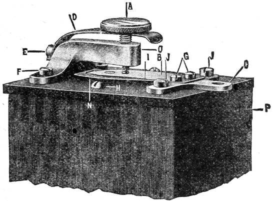
Fig. 95. Kingston Vibrator.
The main objects in view in the construction of a successful vibrator are:
1. To reduce the weight of the moving part as much as possible in order to increase the speed of vibration, and to make the trembler instantly responsive to the timer.
2322. To cause the contact points to separate as rapidly as possible in order to cause the maximum spark.
3. To have the contacts as hard and infusible as possible to resist wear and the action of the spark between the contacts.
4. To make any adjustments that may be required, due to wear, as simple and accessible as possible.
The types of vibrators are legion, and we have not the space to go into the details of all the prominent makes, but will illustrate and describe two well known types.
The Kingston vibrator made by the Kokomo Electric Company, is a good example of a modern vibrator and is shown in detail by Fig. 95. All adjustments between the contact points are made by means of the contact screw A which carries a platinum point at its inner end. The retaining spring D keeps the contact screw from being jarred out of place by the engine vibration, without the use of lock nuts. Turning A against the vibrator, the tension of the spring B is increased, raising the screw decreases the tension. Increasing the tension screw increases the length and heat of the spark, and also increases the current consumption. At N is a separate thin iron plate which is acted on by the magnetized core, a rivet fastening the plate to the main vibrator spring is shown at the end of the spring. The current enters through the lug C, and from this point the circuit is the same as shown in the coil diagram.
(91) Operation of the Jump Spark Coil.
The spark produced by a coil in good condition should be blue-white with a small pinkish flame surrounding it, when the gap is ¼ of an inch or less. The sparks should pass in a continuous stream with this length of gap without irregular stopping and starting of the vibrator. Coils giving a sputtering, weak discharge that causes sparks to fly in all directions are broken down and should be remedied.
The secondary windings of coils are often punctured or broken down by operating the coil with the high tension circuit open, or by trying to cause long sparks by increasing the spark gap over ⅜ of an inch in the open air. Coils are also broken down by allowing excessive currents to flow in the primary coil. Never cause a spark to jump over ⅜ of an inch.
High compression in the cylinder shortens the jumping distance of a high tension spark. Coils that will cause a stream of sparks to flow across a gap of ½ an inch in the open air are often unable to cause a single spark to jump a gap of 1 32 233of an inch under a compression of 80 pounds per square inch in the cylinder.
Remember that a hot spark causes rapid combustion, and will fire a greater range of mixtures and “leaner” charges, than a straggling, thin, weak spark. Spark coils that give poor results with a long spark gap under high compression are often benefited by the shortening of the spark gap. Shortening the gap will increase the heat of the spark, and will insure the passing of a spark each time that the timer makes contact. A good coil should have no difficulty in igniting a piece of paper inserted between the wires forming the spark gap in the open air.
Fig. 96. Kingston Dash Coil.
The adjusting screw affords a means of increasing or decreasing the tension of the vibrator spring, and the amount of battery or magneto current flowing through the primary coil. Increasing the tension of the spring requires stronger magnetization of the core to break the circuit of the contact points. This in turn calls for more current from the battery; hence in order to lessen the demand for current on the battery, the tension should be as little as possible to obtain the necessary spark. An increased tension produces more spark as the magnetization of the core is increased, but for the sake of your batteries decrease the tension as much as possible with a satisfactory spark.
Almost all operators have a tendency to run with too stiff a vibrator, and hence use too much current. An efficient coil should develop a satisfactory spark with ¼ to ½ of an ampere of current in the primary coil. I have often found coils that would work well with ½ ampere, that were screwed up so tight that the coils were consuming 4 to 5 amperes or 8 to 10 times as much as they should.
234A battery ammeter used for testing the current consumed by coil will save its cost many times over in batteries and burnt points if used at frequent intervals in the primary circuit.
An automobile or marine engine should be tested for vibrator adjustment in the following way:
Adjust vibrator so that spring is rather stiff. Start engine and get it thoroughly warmed up and running at full speed, then slowly and gradually decrease the tension of the spring until misfiring starts in; then slowly increase tension until misfiring stops. Increase the tension no farther; this is the correct adjustment.
Poor vibrator adjustment is the cause of much trouble and expense as it uses up the batteries and wastes fuel. The principles of correct adjustment are simple, the adjustment easily made, and there is no possible excuse for the high current consumption and rapid battery deterioration met in every day practice. The usual practice of the average operator is to tighten the vibrator until the spark (observed in the open air) is at its maximum. This is commonly known as “adjusting the coil;” shortly after you hear of him throwing out his batteries as no good. After once getting the vibrator in proper trim the ear will give much information as to the adjustment.
A vibrator adjusted too lightly will cause “skipping” or misfiring with the consequent loss of power.
Never attempt to operate a coil that is damp; the coil will be ruined beyond repair. Above all, do not place the coil in a hot oven to dry, as the box is filled with wax, and if this is melted it will run out and reduce the insulation of the coil. Dry coil gradually.
If the batteries are new or too strong the vibrator may be held against the core of the coil so that the vibrator will not buzz. If this is the case loosen the screw until it works at the proper speed. If the batteries are weak, the coil may not be magnetized sufficiently to draw the vibrator and break the circuit. If this is the case tighten the screw. If the vibrator refuses to work with the battery and wiring in good condition, and if you are sure that the current reaches the coil, look for dirty or pitted contacts on the vibrator.
Should the contact points be dirty, clean them thoroughly by scraping with a knife or sandpaper. Water on the points will stop the vibrator, as will oil or grease.
If contact points are of a uniform gray color on their contact surfaces, and are smooth and flat without holes, pits or 235raised points, they are in good condition. If pits, discolorations or projections are noted, the contact surfaces should be brought to a square, even bearing by means of a small, fine file. The point should not come into contact on an edge, but should bear on each other over their entire surface. Do not use sand paper to remove pitting, as it is almost impossible to secure an even, flat surface by this means.
It is best to remove the contact screw and vibrator blade for examination and cleaning, as it is much easier to file the points square and straight when removed from the coil.
Be careful not to bend the vibrator spring when cleaning, as the adjustment will be impaired. When replacing contact screw and vibrator blade in coil, be careful that they are in exactly the same relative position as they were before removing. Also be sure that the contacts meet and bear uniformly on their surfaces.
(92) Primary Timer.
The duty of the primary timer is to close the primary circuit of the spark coil at, or a little before the time at which the explosive of the charge is required. The exact time at which the timer closes the circuit depends on the load, the speed, and the nature of the fuel. The lapse of time between the instant that the timer closes the circuit and the instant at which the piston reaches the end of the compression stroke is called the “advance” of the timer. When the timer closes the circuit after the piston reaches the end of the stroke, the timer is said to be “retarded.” The timer is constructed so that the time of ignition or the advance and retard can be varied between wide limits. Advancing the spark too far will cause hammering and power loss as the piston will work against the pressure of the explosion.
Retarding the spark will cause a loss of power, as the compression will be less when the piston starts on the outward stroke; and also for the reason that more of the heat will be given up to the cylinder walls as the combustion will be slower. The pressure in the cylinder is less with retarded ignition. Greatly retarded ignition often causes overheating of the cylinder walls, especially with air cooled engines, and also overheats and destroys the seat and valve stem of the exhaust valve. Do not expect the engine to develop its rated horse-power or run efficiently with a late, or retarded spark.
When the engine is installed, and before the timer wears or 236has a chance to get out of adjustment, look it over carefully and see whether the maker has left any marks relating to the timing of the spark. If there are no marks, it is well to determine the relation between the position of the piston and the timer, as the efficiency of the engine depends to a great degree upon the firing point.
Timers are advanced and retarded by partially rotating the housing either in one direction or the other. When the timer is mounted directly on the cam shaft with the cam shaft traveling in a direction opposite to that of the crank shaft, the timer will be retarded by moving it in the same direction as the cam shaft travels, moving it against cam shaft rotation advances the spark.
Timers for two stroke cycle engines rotate at crank shaft speed, and the direction of advance and retard varies with the methods adopted for driving the timer.
(93) Timer Construction.
Fig. 97 shows a typical timer and circuit arranged for a four cylinder engine. The device can be arranged for any number of cylinders, however, by changing the number of sectors, the sectors being equal to the number of cylinders. There are timers on the market that differ from the one shown in the diagram but the principle of operation is the same with all. The shaft E is usually connected to the cam shaft and is electrically grounded to the engine frame at L by means of the bearing in which the shaft rotates.
The lever F mounted on the shaft E carries the pivoted arm H which is free to move on the pivot to a limited extent to allow for wear on the walls W-W-W-W. At one extremity of H is the roller I which rotates on the pin J, as the roller runs around W-W-W-W. At the other extremity of H is fastened the spring S, which forces I into contact with the walls. A-B-C-D are metallic contact sectors whose connections lead to the four spark coils.
When the metal roller I comes into contact with one of the sectors as at B, the sector is grounded to the engine frame by the roller, the current traveling through the roller and its pin, through lever H and its pin, through the lever F and shaft E to ground at L, the course of the current being indicated by the arrows.
237
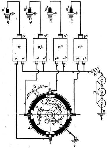
Fig. 97. Timer Diagram.
As the shaft E rotates and carries with it roller I, the roller makes contact with the sectors in order B-C-D-A, if rotated in the direction shown by arrow, which rotation grounds the primary coils of the spark coils R3-R4-R1-R2 in succession; the connection from the timer to the primary being to the primary binding posts P3-P4-P1-P2. A high tension spark occurs at each contact of the roller with the sectors, as the contact allows current to flow through the primary of the coils. The high tension 238binding posts S1-S2-S3-S4 are connected with the spark plugs or spark gaps U1-U2-U3-U4 by means of high tension cables. As soon as the timer grounds a coil, the coil produces a high tension spark in its corresponding spark plug.
It is evident from the foregoing that the timer not only determines the time at which a spark will take place, but it also determines the cylinder in which the spark will be produced, providing of course that a spark coil is provided for each cylinder.
The contact sectors A-B-C-D are insulated from each other by the insulating walls W-W-W-W, the inner surface of which provides a path on which the contact roller I revolves.
The contact sectors and insulating walls are encased by the protective housing Z, to which they are rigidly fastened.
The housing Z can be moved back and forth on the shaft E for advance and retard, by means of the lever K.
The current flows from the battery terminal V (with the roller in the position shown) through the switch M, through coil R3, post P3 to sector B, from which it passes through the roller I, levers H and F to ground. From the ground on the engine frame the current flows back to its source, the battery O, thus completing the circuit. When the roller makes contact with sector C, the coil R4 is energized, contact with D energizes R1, and so on. No two coils can be thrown on simultaneously as only one coil is grounded at a time. The high tension current flows from each coil to its plug as soon as the current passes through the primary of that coil.