EXPLANATION OF THE FIGURES.
Reading edition
Plate II
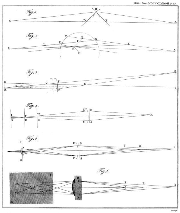
Plate II. Fig. 1. See Page 28. Prop. III.
Fig. 2. See Page 28. Prop. IV.
Fig. 3. See Page 31. Prop. V.
Fig. 4—6. Relating to the optometer. See Page 34.
Plate III
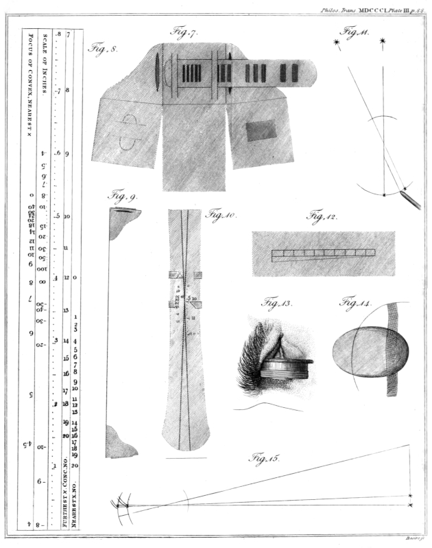
Plate III. Fig. 7. The form of the ends of the optometer, when made of card. The apertures in the shoulders are for holding a lens: the square ends turn under, and are fastened together.
Fig. 8. The scale of the optometer. The middle line is divided, from the lower end, into inches. The next column shows the number of a concave lens requisite for a short- sighted eye; by looking through the slider and observing the number opposite to which the intersection appears when most remote. By observing the place of apparent intersection when nearest, the number requisite will be found in the other column, provided that the eye have the average power of accommodation. At the other end, the middle line is graduated for extending the scale of inches by means of a lens four inches in focus; the negative numbers implying that such rays as proceed from them are made to converge towards a point on the other side of the lens. The other column shows the focal length of convex glasses required by those eyes to which the intersection appears, when nearest, opposite the respective places of the numbers.
Fig. 9. A side view of the optometer, half its size.
Fig. 10. The appearance of the lines through the slider.
Fig. 11. Method of measuring the magnitude of an image on the retina. See Page 48.
Fig. 12. Diagonal scale drawn on a looking-glass.
Fig. 13. The method of applying a lens with water to the cornea.
Fig. 14. The appearance of a spectrum occasioned by pressure; and the inflection of straight lines seen within the limits of the spectrum.
Fig. 15. An illustration of the enlargement of the image, which would be the consequence of an elongation of the eye: the images of the candles which, in one instance, fall on the insertion of the nerve, falling, in the other instance, beyond it.
Plate IV
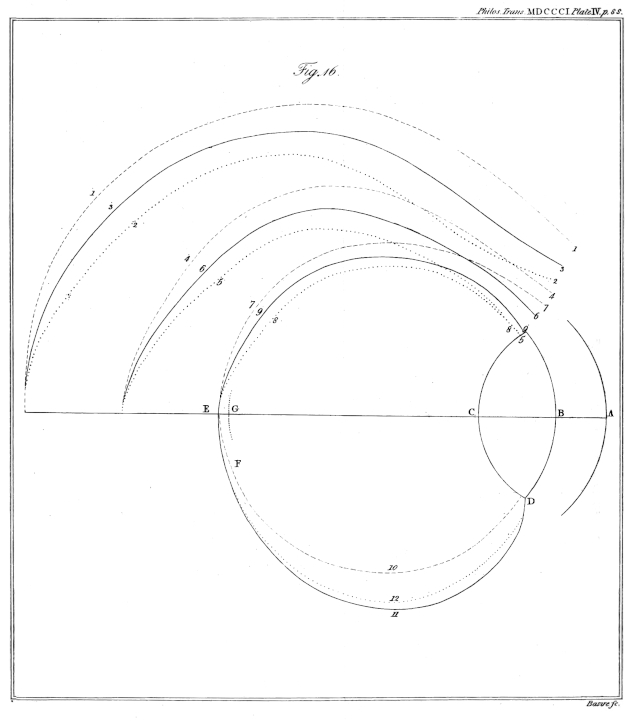
Plate IV. Fig. 16. The successive forms of the image of a large distant object, as it would be delineated by each refractive surface in the eye; to show how that form at last coincides with the retina. E G is the distance between the foci of horizontal and vertical rays in my eye.
Plate V
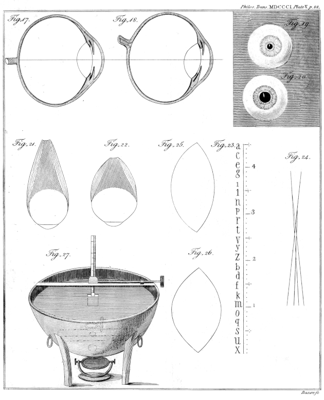
Plate V. Fig. 17. Vertical section of my right eye, seen from without; twice the natural size.
Fig. 18. Horizontal section, seen from above.
Fig. 19. Front view of my left eye when the pupil is contracted; of the natural size.
Fig. 20. The same view when the pupil is dilated.
Fig. 21. Outline of the eye and its straight muscles when at rest.
Fig. 22. Change of figure which would be the consequence of the action of those muscles upon the eye, and upon the adipose substance behind it.
Fig. 23. Scale of the small optometer.
Fig. 24. Appearance of four images of a line seen by my eye when its focus is shortest.
Fig. 25. Outline of the lens when relaxed; from a comparison of M. Petit’s measures with the phenomena of my own eye, and on the supposition that it is found in a relaxed state after death.
Fig. 26. Outline of the lens sufficiently changed to produce the shortest focal distance.
Fig. 27. Apparatus for ascertaining the focal length of the lens in water.
Plate VI
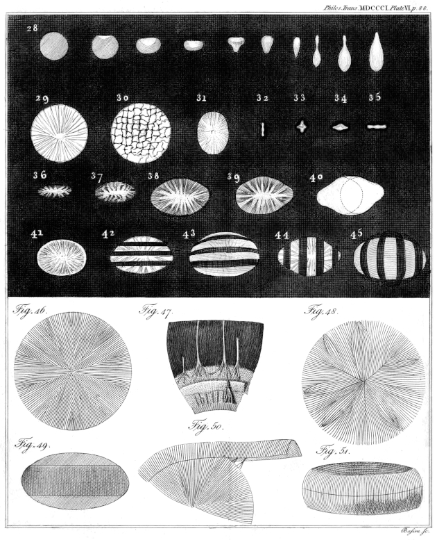
Plate VI. Fig. 28. Various forms of the image depicted by a cylindrical pencil of rays obliquely refracted by a spherical surface, when received on planes at distances progressively greater.
Fig. 29. Image of a minute lucid object held very near to my eye.
Fig. 30. The same appearance when the eye has been rubbed.
Fig. 31—37. Different forms of the image of a lucid point at greater and greater distances; the most perfect focus being like Fig. 33, but much smaller.
Fig. 38. Image of a very remote point seen by my right eye.
Fig. 39. Image of a remote point seen by my left eye; being more obtuse at one end, probably from a less obliquity of the posterior surface of the crystalline lens.
Fig. 40. Combination of two figures similar to the fifth variety of Fig. 28; to imitate Fig. 38.
Fig. 41. Appearance of a distant lucid point when the eye is adapted to a very near object.
Fig. 42, 44. Shadow of parallel wires in the image of a distant point, when the eye is relaxed.
Fig. 43, 45. The same shadows rendered curved by a change in the figure of the crystalline lens.
Fig. 46. The order of the fibres of the human crystalline.
Fig. 47. The division of the nerves at the ciliary zone; the sclerotica being removed. One of the nerves of the uvea is seen passing forwards and subdividing. From the calf.
Fig. 48. Ramifications from the margin of the crystalline lens.
Fig. 49. The zone of the crystalline faintly seen through the capsule.
Fig. 50. The zone raised from its situation, with the ramifications passing through it into the lens.
Fig. 51. The zone of the crystalline detached.
Plate VII
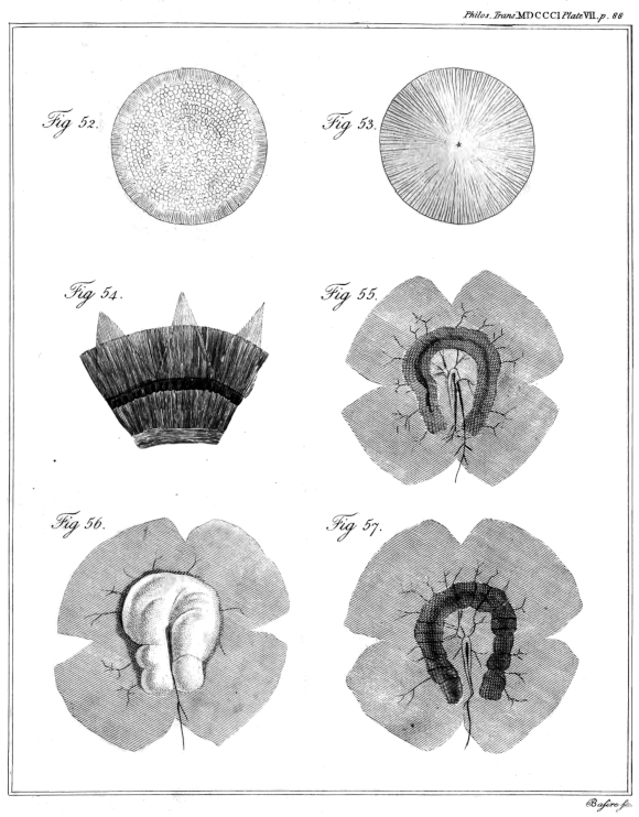
Plate VII. Fig. 52. The crenated zone, and the globules regularly arranged on the crystalline of the partridge.
Fig. 53. The order of the fibres in the lens of birds and fishes.
Fig. 54. The segments of the capsule of the crystalline turned back, to show the detached ciliary processes. From the calf.
Fig. 55. Part of the choroid of the cod-fish, with its red substance. The central artery hangs loose from the insertion of the nerve.
Fig. 56. The membrane covering this substance internally, raised by the blow-pipe.
Fig. 57. The appearance of the red substance, after the removal of the membrane.