Chapter XVIII · THEATER WIRING. (continued 2)
Reading edition
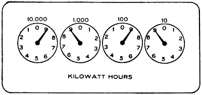
FIGURE 166.
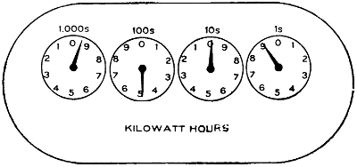
FIGURE 167.
At the top of each dial the value of the reading of that dial is shown. Where the figures given are followed by the letter “s”, as in Figures 167 and 168, it signifies that each division of the dial represents the amount of energy indicated by the figures at the top. For instance, in Figure 168 each division of the dial at the right represents one-tenth of one kilowatt hour and a total revolution of the pointer ten-tenths, or one kilowatt hour.
If the figures given at the top of the dial are not followed by the letter “s”, or as shown in Figure 166, each division of the dial represents one-tenth of the amount shown at the top of the dial, the dial at the right of Figure 166 indicating nine-tenths of ten kilowatts or nine kilowatts.
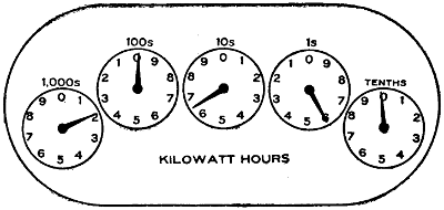
FIGURE 168.
The meter must always be read from right to left, the lowest indicating dial being the one at the extreme right, and the lower reading ones always being used to check the higher ones just at the left. The following example will illustrate the manner of reading meters:
In Figure 165 the right-hand pointer registers nine-tenths of 1000, or 900 watt hours; the pointer next to it registers eight, since it cannot be considered as fully up to any number unless the pointer at the right of it has just arrived at or passed 0. By the same token the middle pointer also registers 8 and as the middle pointer has not reached 0 the one at the left of it must be read as one, the last dial also indicates one and the total reading is 1,188,900. On some types of meters a multiplier is used. This is generally given on the meter dial and the readings given by the pointers must be multiplied by this number to obtain the correct reading of the meter.
Motors.
Motors.—Motors are used in theaters for ventilation, for raising and lowering the steel curtain in cities where such are required, and also in some cases for operating drop curtains, but for this last purpose they have not found much favor. In some localities motors are required to keep up a certain water pressure to be used in case of fire. Voltages higher than 550 are not considered in theater work.
National Electrical Code Rules for 550-volt Motors and Less.
Motors operating at a potential of 550 volts or less must be thoroughly insulated from the ground wherever feasible. Wooden base frames used for this purpose, and wooden floors, which are depended upon for insulation where, for any reason, it is necessary to omit the base frames, must be kept filled to prevent absorption of moisture, and must be kept clean and dry. Where frame insulation is impracticable special permission in writing may be given for its omission, in which case the frame must be permanently and effectively grounded.
The motor leads or branch circuits must be designed to carry a current at least 25 per cent greater than that for which the motor is rated. Where the wires under this rule would be over-fused in order to provide for the starting current, as in the case of many of the alternating-current motors, the wires must be of such size as to be properly protected by these larger fuses.
Each motor and resistance box must be protected by a cut-out and controlled by a switch; said switch plainly indicating whether “on” or “off”.
Small motors may be grouped under the protection of a single set of fuses, provided the rated capacity of the fuses does not exceed 6 amperes. With motors of one-fourth horse power or less, on circuits where the voltage does not exceed 300, single-pole switches may be used. The switch and rheostat must be located within sight of the motor, except in cases where special permission to locate them elsewhere is given, in writing.
Where the circuit-breaking device on the motor-starting rheostat disconnects all wires of the circuit, the switch called for in this section may be omitted. Overload-release devices on motor-starting rheostats will not be considered to take the place of the cut-out required by this section. An automatic circuit-breaker disconnecting all wires of the circuit may serve as both switch and cut-out.
Auto starters, unless equipped with tight casings enclosing all current-carrying parts, in all wet, dusty, or linty places, must be enclosed in dust-tight, fireproof cabinets. Where there is any liability of short circuits across their exposed live parts being caused by accidental contacts, a railing must be erected around them.
Must not be run in series-multiple or multiple-series, except on constant-potential systems, and then only by special permission.
Must, when combined with ceiling fans, be hung from insulated hooks, or else there must be an insulator interposed between the motor and its support.
Must each be provided with a name-plate, giving the maker’s name, the capacity in volts and amperes, and the normal speed in revolutions per minute.
All varying (or variable) speed alternating-current motors except those used for railway service must be marked with the maximum current which they can safely carry for 30 minutes, starting cold.
Terminal blocks when used on motors must be made of approved non-combustible, non-absorptive, insulating material such as slate, marble, or porcelain.
Adjustable-speed motors, unless of special and appropriate design, if controlled by means of field regulation, must be so arranged and connected that they cannot be started under weakened field.
The use of soft rubber bushings to protect the lead wires coming through the frames of motors is permitted, except when installed where oils, grease, oily vapors, or other substances known to have rapid deleterious effect on rubber are present in such quantities and in such proximity to motors as may cause such bushings to be liable to rapid destruction. In such cases hardwood properly filled, or preferably porcelain or micanite bushings must be used.
The following table shows the sizes of wire recommended to be used with motors of the horsepower given. This table is an extract from the rules of the Department of Gas and Electricity of the City of Chicago. The column headed “Mains” may be used when there are a number of motors fed by a single line. For all lines which supply a single motor only, the column headed “Branches” must be used.
The difference between the two is due to the fact that it is not believed that several motors fed by a single line will all be started at the same time; hence it is not necessary to provide the overload capacity for all of the motors as it is where but a single motor is installed.
Table VIII. SIZE OF WIRES FOR MOTORS OF DIFFERENT HORSE POWER.
DIRECT CURRENT
110 Volts 220 Volts
H. P. Full- load Current Size of Wire Mains Size of Wire Branches Full- load Current Size of Wire Mains Size of Wire Branches
1 8 14 14 4 14 14
2 15 14 12 8 14 14
3 23 10 8 12 14 14
4 30 8 6 15 14 12
5 38 6 6 19 12 10
7 .5 56 5 4 28 8 8
10 75 3 1 38 6 6
SINGLE-PHASE
1 12 ... 12 6 ... 14
2 23 ... 8 11 ... 12
3 33 ... 6 16 ... 10
4 44 ... 4 22 ... 8
5 53 ... 3 26 ... 6
THREE-PHASE
1 ... ... ... 3 14 14
2 ... ... ... 5 14 14
3 ... ... ... 8 14 14
4 ... ... ... 10 14 14
5 ... ... ... 13 14 12
7 .5 ... ... ... 19 12 8
10 ... ... ... 26 8 6
Music Stands.
Music Stands.—Music stands are used by the musicians and are generally placed between the first row of seats and the stage. Each musician should be provided with an individual stand, although if necessary, two or three can get along with one stand.
No first-class theater should be fitted up with less than twenty outlets for musicians’ lights. In the Metropolitan Opera House of New York there are one hundred. Houses used exclusively for vaudeville do not, however, need that many. In houses devoted to grand opera, often as many as one hundred or more musicians are employed at the same time. To take care of such a number, the music stands should be wired with pin-plug connectors so that connections may be made from one to the other. Long flexible connections are necessary for most music stands.
Sometimes it is necessary to crowd the orchestra under the stage and at other times, with musical comedies, for instance, they must be brought out where they can see the movements of the actors.
The more the circuits are subdivided, and the different lights made independent of each other, the better it will be and the less the annoyance in case a fuse blows. The fuses should always be arranged at the switchboard so that it will not be necessary for the electrician to work in front of the audience in cases of trouble. For this reason extra stands should also be kept on hand.
A main switch controlling the lights should be placed where one of the musicians can handle it. In dark scenes these lights must often be turned out. If these lights are left under the control of the stage electrician they will be more likely to be forgotten at the critical moment than if under the control of the men who need them.
An eight candle-power lamp for each stand will be sufficient and this is usually placed inside a special reflector which allows the light to fall upon the music sheet only. Stage cable of good quality should be used for the connections; there is too much rough handling for reinforced cord. The use of the ordinary attachment plug should be avoided; use approved pin-plug connectors.
Open Work.
Open Work.—Open work is not allowed in theaters.
Operating Room.
Operating Room.—See special chapter on “Operating Room.”
Panel Boards.
Panel Boards.—Panel boards are really small switchboards, the switches and cut-outs being mounted usually upon slate. The slate must be free of metal seams; these, if present, often manifest themselves by heating. Panel boards, unless located in the immediate vicinity of the main switchboard, and where they are enclosed in a compartment, must always be placed in standard metal cabinets.
National Electrical Code Rules for Panel Boards.
The following specifications are intended to apply to all panel and distributing boards used for the control of light and power circuits, but not to such switchboards in central stations, sub-stations, or isolated plants as directly control energy derived from generators or transforming devices.
Design.
The specifications for construction of switches and cut-outs given in the following pages must be followed as far as they apply.
In the relative arrangement of fuses and switches, the fuses may be placed between the bus-bars and the switches, or between the switches and the circuits, except in the case of service switches. When the branch switches are between the fuses and the bus-bars, the connections must be so arranged that the blades will be dead when the switches are open.
When there are exposed live-metal parts on the back of a board, a space of at least one-half inch must be provided between such live metal parts and the cabinet in which the board is mounted.
Spacings.
Table IX. THE MINIMUM DISTANCE THAT MUST BE MAINTAINED BETWEEN BARE LIVE METAL PARTS (BUS-BARS, ETC.)
Between Parts of Opposite Polarity, Except at Switches and Link Fuses Between Parts of Same Polarity at Link Fuses
When Mounted on the Same Surface When Held Free in Air
Not over 125 volts 3⁄4 inch 1⁄2 inch 1⁄2 inch
Not over 250 volts 1 1⁄4 inch 3⁄4 inch 3⁄4 inch
Not over 600 volts 2 3⁄4 inch 1 3⁄4 inch
At switches or enclosed fuses, parts of the same polarity may be placed as close together as convenience in handling will allow. It should be noted that the above distances are the minimum allowable, and it is urged that greater distances be adopted wherever the conditions will permit.
The spacings given in the first column apply to the branch conductors where enclosed fuses are used. Where link fuses or knife switches are used, the spacings must be at least as great as those given in the following section on fuse spacing. The spacings given in the second column above apply to the distance between the raised main bars and between these bars and the branch bars over which they pass. The spacings given in the third column are intended to prevent the melting of a link fuse by the blowing of an adjacent fuse of the same polarity.
Panel boards of special design, in which the insulation and separation between the bus-bars, and between the other current-carrying parts is secured by means of barriers or insulating materials instead of by the spacings given above, must be submitted for special examination and approved before being used.
Fuse Spacings.
Spacings must be at least as great as those given in Table X, which applies only to plain, open link fuses. The spaces given are correct for fuse blocks to be used on direct-current systems, and can therefore be safely followed in devices designed for alternating currents. If the copper fuse tips overhang the edges of the fuse block terminals, the spacings should be measured between the nearest edges of the tips.
A space must be maintained between fuse terminals of the same polarity of at least one-half of an inch for voltages up to 125 and of at least three-quarters of an inch for voltages from 125 to 250. This is the minimum distance allowable, and greater separation should be provided when practicable.
For 250 volts, boards, or blocks with the ordinary front-connected terminals, except where these have a mass of compact form equivalent to the back-connected terminals usually found in switchboard work, a substantial barrier of insulating material, not less than one-eighth of an inch in thickness, must be placed in the “break” gap—this barrier to extend out from the base at least one-eighth of an inch farther than any bare live part of the fuse-block terminal, including binding screws, nuts and the like.
For three-wire systems cut-outs must have the break-distance required for circuits of the potential of the outside wires.
Table X. FUSE SPACINGS.
Not over 125 volts: Minimum Separation of Nearest Metal Parts of Opposite Polarity Minimum Break Distance
10 amperes or less 3⁄4 inch 3⁄4 inch
11-100 amperes 1 3⁄4 inch 3⁄4 inch
101-300 amperes 1 3⁄4 inch 1 3⁄4 inch
301-1,000 amperes 1 1⁄4 inches 1 1⁄4 inches
Not over 250 volts: Minimum Separation of Nearest Metal Parts of Opposite Polarity Minimum Break Distance
10 amperes or less 1 1⁄2 inches 1 1⁄4 inches
11-100 amperes 1 3⁄4 inches 1 1⁄4 inches
101-300 amperes 2 3⁄4 inches 1 1⁄2 inches
301-1,000 amperes 2 1⁄2 inches 2 3⁄4 inches
Switch Spacings and Dimensions.
When designed with 250-volt spacings between adjacent blades, triple-pole switches must be marked 250 volts and may be used on 3-wire D. C. or single-phase systems having not more than 250 volts between adjacent wires and not more than 500 volts between the two outside wires.
Spacings and dimensions must be at least as great as those given below:
Table XI A. SWITCH SPACINGS AND DIMENSIONS FOR SWITCH-BOARDS AND PANEL BOARDS.
Not Over 125 Volts D. C. and A. C.
Current Width and Thickness Minimum Separation of Nearest Metal parts of Opposite Polarity Minimum Break Distance
Blades Clips and Hinges
30 amp. 1⁄2 inch by 5⁄64 inch 1⁄2 inch by 3⁄64 inch 1 1⁄4 inch 3⁄4 inch
60 amp. 1 1⁄4 inch 1 3⁄4 inch
Table XI B. SWITCH SPACINGS AND DIMENSIONS FOR INDIVIDUAL SWITCHES.
Not Over 125 Volts D. C. and A. C.
Inch Inch Inch Inch
30 amperes 1⁄2 by 5⁄64 1⁄2 by 3⁄64 1 1⁄4 1
60 and 100 amperes 1 1⁄2 1 1⁄4
200 amperes 2 1⁄4 2
400 and 600 amperes 2 3⁄4 2 1⁄2
800 and 1000 amperes 3 2 3⁄4
A 300-ampere switch with the spacings of the 200-ampere switch above may be used on switchboards.
Table XI C. SWITCH SPACINGS AND DIMENSIONS FOR ALL SWITCHES.
250 Volts Only D. C. and A. C.
Inch Inch Inch Inch
30 amperes 1⁄2 by 5⁄64 1⁄2 by 3⁄64 1 3⁄4 1 1⁄2
Table XI D. SWITCH SPACINGS AND DIMENSIONS FOR ALL SWITCHES.
Not Over 250 Volts D. C. nor Over 500 Volts A. C.
Inch Inch Inch Inch
30 amperes 5⁄8 by 1⁄8 5⁄8 by 1⁄16 2 1⁄4 2
60 and 100 amperes 2 1⁄4 2
200 amperes 2 1⁄2 2 1⁄4
400 and 600 amperes 2 3⁄4 2 1⁄2
800 and 1000 amperes 3 2 3⁄4
A 300-ampere switch with the spacings of the 200-ampere switch above may be used on switchboards.
Cut-out terminals on switches for over 250 volts must be designed and spaced for 600-volt fuses.
Table XI E. SWITCH SPACINGS AND DIMENSIONS FOR ALL SWITCHES.
Not Over 600 Volts D. C. and A. C.
Inch Inch Inch Inch
30 amperes 5⁄8 by 1⁄8 5⁄8 by 1⁄16 4 3 1⁄2
60 amperes 4 3 1⁄2
100 amperes 4 1⁄2 4
Paint Bridge.
Paint Bridge.—The paint bridge is usually a scaffold which can be raised and lowered, and which serves the purpose of carrying scene painters at work on the curtains. A long strip is the best means of illumination and it must be connected with long stage cable so as to be portable.
Paint Room.
Paint Room.—Rooms in which paints are stored should not contain switches or cut-outs. Lamps should be incased in vapor-tight globes.
Program Board.
Program Board.—A simple form of program board is shown in Figure 169. Except at the top and the bottom, where three lamps are shown together in one compartment, each lamp is incased by itself. In front of the lamps is usually colored glass, bearing numbers or letters. The lamp behind any number being turned on, that number becomes visible. The top and bottom are usually labeled, “Special”, or “Extra”.
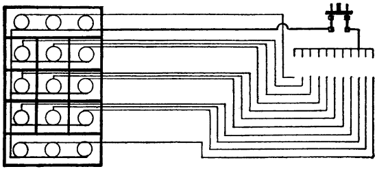
FIGURE 169.
Another form of program board is shown in Figure 170. This requires much more wiring. Each lamp on the board is connected to a plug or switch at the operator’s station. Whichever switch is closed on the small board at the right causes a corresponding light on the large board to appear.
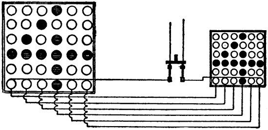
FIGURE 170.
Two program boards are usually installed, one at each side of the stage, facing the audience at angles, so that one can be seen from the extreme right, the other from the extreme left.
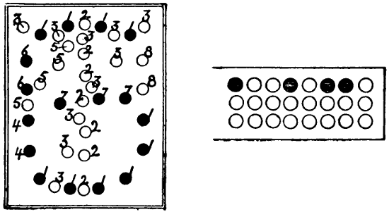
FIGURE 171.
A system that is often used for carriage call is shown in Figure 171. The lights are arranged on circuits as indicated by numbers. All lamps bearing the same number being connected to one wire leading to the controlling station. Thus there are eight controlling or switch wires and there is one wire common to all. A special switch is provided which has a contact point for each wire. Paper cards, perforated specially for the numbers they represent, are used. If a card bearing a certain number is inserted in the proper place and the switch closed, the number printed on the card will appear on the sign. If, for instance, the shaded circles in the card at the left of the figure allow contact to be made, the lights indicated by black circles will light up and make the figure “6”.
Another form of program or call board is shown in Figure 172. This requires more wires than the one just described, one wire being carried to the controlling board from each lamp. The connections may be made in various ways. Sometimes they are made with knife switches. If it is desired to make the figure 1, for instance, only the three lights in a vertical row in the center need be lighted, and to do this the three wires from those lamps must be connected to one switch. To make the figure 2, seven lamps would have to be lit by another switch. It is capable of making any letter or number and when used as a program board only may be somewhat simplified.

FIGURE 172.
In connection with these signs a large number of wires may be required and attention should be given to the following rule:
National Electrical Code Rule for Wiring Program and Call Boards.
Except in the case of stage pockets the same conduit must never contain more than four two-wire, or three three-wire circuits of the same system except by special permission, and must never contain circuits of different systems.
Proscenium Side Lights.
Proscenium Side Lights.—These lights are located on each side of the stage, as near as possible to the edge of the proscenium opening and often in front of the steel curtain. They are of more use in musical productions, where choruses spread over the whole stage, than in dramatic productions where the interest is more in the center of the stage. In some theaters the proscenium side lights extend the full height of the opening and are arranged for three colors in the same manner as footlights and borders. Very often, however, only ten or twelve lights are arranged on each side of the stage.
The construction rules are the same as those governing foot-lights.
Lamps must be protected by strong wire mesh. This is essential as in many cases actors are very likely to back into them while passing off the stage. Portable strips are sometimes used as proscenium side lights.
Receptacles.
Receptacles.—See “Stage Pockets”.
Retiring Rooms.
Retiring Rooms.—In these places a quiet subdued illumination is usually desired. There are also often quaint objects and effects to be illuminated. A large number of outlets conveniently located for the use of table lamps, fire places, and illumination of pictures, should be provided.
Rheostats.
Rheostats.
National Electrical Code Rules for Rheostats.
Location.
Must be placed on a switchboard, or at a distance of at least one foot from combustible material, or separated therefrom by a slab or panel of non-combustible, non-absorptive, insulating material such as slate, soapstone, or marble, somewhat larger than the rheostat, which must be secured in position independently of the rheostat supports. Bolts for supporting the rheostat shall be countersunk at least one-eighth inch below the surface at the back of the slab and the bolt heads shall be covered with insulating material. For proper mechanical strength, slab should be of a thickness consistent with the size and weight of the rheostat, and in no case to be less than one-half inch.
If resistance devices are installed in rooms where dust or combustible flyings would be liable to accumulate on them, they must be equipped with dust-proof face plates.
Materials.
Must be made entirely of non-combustible materials, except such minor parts as handles, magnet insulation, etc. All segments, lever arms, etc., must be mounted on non-combustible, non-absorptive, insulating material.
Connections.
Clamps for connecting wires to the terminals must be so designed as to insure a thoroughly good connection and must be sufficiently strong and heavy to withstand hard usage. For currents above 30 amperes, lugs into which the connecting wires may be soldered, or approved solderless connectors must be used. Clamps or lugs will not be required when leads are provided as a part of the device.
No-Voltage Release.
Motor-starting rheostats must be so designed that the contact arm cannot be left on intermediate segments, and for direct-current circuits must be provided with an automatic device which will interrupt the supply circuit before the speed of the motor falls to less than one-third of its normal value. In motor-starting rheostats for alternating-current circuits the automatic interrupting device may be omitted.
Overload Release.
Overload-release devices which are inoperative during the process of starting a motor will not be approved, unless other circuit-breakers or fuses are installed in connection with them.
Signals.
Signals.—Signals are necessary between the manager’s office and the stage electrician’s station; for this purpose telephones are generally used. In many cities a fire-alarm signal system is also required and it is specified to what part of the house it shall lead. In addition to the above, a means of signalling the fly floor and the orchestra leader must be provided. Buzzers are used for these signals. It is best to use batteries for all these signals instead of attempting to run them from lighting circuits. Means of signalling the arc-lamp station in the gallery or the balcony should also be provided for use in connection with lantern slides, etc. Telephone connection to this point will also be very useful in order to give instructions to the lamp operator. Return-call systems are advisable in all places so that the electrician can be called from any point.
In some cities the local laws require these wires to be in conduit so as to preclude any possibility of their communicating fire to anything. At any rate the wires should be very carefully installed.
Signs.
Signs.—In nearly all electric signs used about theaters the letters are outlined by incandescent lamps. Small candle-power lamps are always used. They are not only economical but much more attractive because the glare from too much light is very annoying. Many signs are equipped with low candle-power tungsten lamps wired in series. In order that the letters should show to full advantage they should be glossy white and be kept clean. Such letters will show as bright as the lamps. It is best to wire the sign so that either side can be used independent of the other. In many cases, also, signs are wired so that each letter is independent of the others for use with flashers.
Attraction signs are used to advertise the attractions which appear from time to time. Independent portable letters are used and changed as often as the attractions change. Each letter must be fitted with cable and attachment plug of some kind and should have a separate circuit. Cut-outs are generally located on the frame and must be protected from the weather.
Sockets.
Sockets.—Sockets must be of approved construction. Key sockets must not be used for emergency or exit lighting. Sockets with fiber linings must not be used unless protected by insulating joints. In damp places weatherproof sockets must be used. Where inflammable gases exist, lamps must be incased in vapor-proof globes. Porcelain sockets should not be used in theaters. Weatherproof sockets are generally used for portable purposes because they have no screws, etc., to work loose.
Stage Cable.
Stage Cable.—Stage cables are allowed in theaters only where flexible conductors are absolutely necessary. All wiring that can possibly be installed in conduit or strip construction should be so arranged. By the use of plugging boxes the quantity of stage cable necessary can be much reduced. Plugs for arc and incandescent lights must not be interchangeable.
Stage Flues.
Stage Flues.—In most cities stage flues, as described in the chapter on “Theater Buildings”, are required. The requirement is also, often, that they be released by electrical means. The rule below contemplates a circuit containing an electro-magnet and at least two switches in series. The magnet must be energized to hold the ventilator closed. If the current fails or a switch is opened the dampers must fly open at once. Where direct current is available the magnet is usually wound for 110 volts and connected to a circuit that is always alive. In case of an isolated plant which is shut down at night some arrangement for tying the dampers down should be made, but it is not always advisable, as once tied they are likely to remain so and sure to fail when needed. Magnets do not work well on alternating currents and in such cases the magnet should be wound for a small current to be obtained from a gravity battery which may be allowed to be always working. Locate the battery where it will not freeze.
National Electrical Code Rules for Control of Stage Flues.
In cases where dampers are released by an electric device, the electric circuit operating same must be normally closed. Magnet operating dampers must be wound to take full voltage of circuit by which it is supplied, using no resistance device, and must not heat more than normal for apparatus of similar construction. It must be located in loft above scenery, and be installed in a suitable iron box with a tight, self-closing door.
Such dampers must be controlled by at least two standard single-pole switches mounted within approved iron boxes provided with self-closing doors without lock or latch, and located, one at the electrician’s station and the others as designated.
Stage and Gallery Pockets.
Stage and Gallery Pockets.—Stage pockets are usually located on each side of the stage just far enough from the center to be safely back of the scenery. The more pockets there are the better it will be. Each pocket usually contains four circuits, and one of these at least should be for incandescent lights. It will be convenient if the stage pockets are divided into four groups, each group under control of a separate switch and the whole again under control of a main switch. This will enable the operator to throw off all of the pockets at once, if necessary, or to make any combination desired.
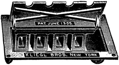
FIGURE 173.
Sometimes lights fed through stage pockets require to be dimmed; but it is hardly practicable to arrange dimmers for apparatus carried by traveling companies, since a dimmer must be selected with respect to the amperage it is to control.
In addition to the rules given below, some cities require the bottom of stage pockets to be open, so as to avoid an accumulation of dust. This is a very essential precaution, as otherwise the pockets soon fill up or require very frequent cleaning. The covers must be substantial as heavy trucks are sometimes run over them. Two illustrations of stage pockets are given in Figures 173 and 174. The plugs used with these boxes are shown in Figure 175.
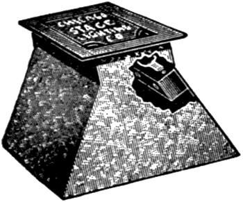
FIGURE 174.
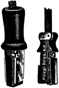
FIGURE 175.
Gallery pockets are not usually laid in the floor but along the railing. The gallery pockets should be under separate control from the stage switchboard.
National Electrical Code Rules for Stage and Gallery Pockets.
Must be of approved type, insulated from ground and controlled from switchboard, each receptacle to be of not less than 35-ampere rating for arc lamps nor 15-ampere for incandescent lamps, and each receptacle to be wired to its full capacity. Arc pockets to be wired with wire not smaller than No. 6 B. & S. gauge and incandescent pockets with not less than No. 12 B. & S. gauge. Plugs for arcs and incandescent pockets must not be interchangeable.
Switches.
Switches.—All knife switches should be enclosed in cabinets unless they are located on a switchboard. In exposed places, flush switches should be used. The usual height at which scattered switches are located is about four and one-half feet above floor. Door switches are of use principally in dressing rooms.
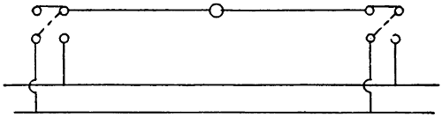
FIGURE 176.
Diagrams of three-way switches are given in Figures 176 and 177. In Figure 177, the wiring by which a light can be controlled from three different points is shown. The middle switch must be a pole-changing switch. In this case a throw-over knife switch is wired to perform this function. Omitting the knife switch we have two three-way switches controlling the light. When both switches (indicated by broken lines) connect to the same wire the light burns.
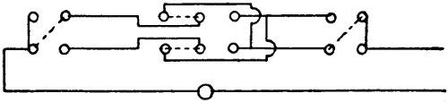
FIGURE 177.
In Figure 176, when both switches connect to the same polarity the light is out; when one of them is connected to the other pole the light burns. Under certain conditions this arrangement is more economical in wire but has the disadvantage which the other method avoids, of bringing both poles to each switch. This method cannot be used with direct-current arc lamps. Three-way switches are useful on stairways, enabling one to turn on a light at the bottom of the stairway and turn it off when at the top or vice versa.
National Electrical Code Rules for Switches and Connections.
Switches.
Must be placed on all service wires, either overhead or underground, in the nearest readily accessible place to the point where the wires enter the building, and arranged to cut off the entire current. Departure from this rule may be authorized only under special permission in writing. Switches controlling emergency lighting must be located only in the lobby.
Must when used for service switches, indicate, on inspection, whether the current be “on” or “off”. Switch cabinets must be deep enough to allow the door to be closed when 30 ampere branch-circuit switches are in any position, and when larger single-throw switches are thrown open as far as their construction and installation will permit.
Must, for constant-current systems, close the main circuit and disconnect the branch wires when turned “off”; must be so constructed that they shall be automatic in action, not stopping between points when started, and must prevent an arc between the points under all circumstances. They must indicate whether the current be “on” or “off”. Service cut-out and switch must be arranged to cut off current from all devices including meters.
Must always be placed in dry, accessible places, and be grouped as far as possible. Single-throw knife switches must be so placed that gravity will not tend to close them. Double-throw knife switches may be mounted so that the throw will be either vertical or horizontal as preferred, but if the throw be vertical a locking device must be provided, so constructed as to insure the blades remaining in the open position when so set.
When practicable switches must be so wired that blades will be “dead” when the switch is open.
When switches are used in rooms where combustible flyings would be likely to accumulate around them, they must be enclosed in dust-tight cabinets.
Up to 250 volts and thirty amperes, approved indicating snap switches are suggested in preference to knife switches on lighting circuits.
Single-pole switches must never be used as service switches nor for the control of outdoor signs or circuits located in damp places, nor placed in the neutral wire of a three-wire system, except in the two-wire branch or tap circuit supplying not more than 660 watts.
Where flush switches or receptacles are used, whether with conduit systems or not, they must be enclosed in an approved box constructed of iron or steel, in addition to the porcelain enclosure of the switch or receptacle.
Hinges of knife switches must not be used to carry current unless they are equipped with spring washers, held by lock-nuts or pins, or their equivalent, so arranged that a firm and secure connection will be maintained at all positions of the switch blades.
Spring washers must be of sufficient strength to take up any wear in the hinge and maintain a good contact at all times.
Connections.
Switches for currents of over thirty amperes must be equipped with lugs, firmly screwed or bolted to the switch, and into which the conducting wire shall be soldered. For the smaller sized switches simple clamps can be employed, provided they are heavy enough to stand considerable hard usage.
Where lugs are not provided, a rugged double-V groove clamp is advised. A set screw gives a contact at only one point, is more likely to become loosened, and is almost sure to cut into the wire. For the smaller sizes, a screw and washer connection with up-turned lugs on the switch terminal gives a satisfactory contact.
Spacings.
See “Panel Boards”.
Switchboards.
Switchboards.—The stage switchboard is usually located on the right-hand side of the stage. This position enables the operator to watch cues easily and handle his switches with the right hand. This side is also the one from which the stage manager prefers to work. It is preferable to have the board raised high enough above stage level to allow all space on the stage to be used by actors. If the switchboard is located on stage level it takes up much room that is valuable and makes stage exits for actors difficult.
The wiring of a good switchboard should be divided into three parts, each part independent of the others, so that any one part can be entirely cut off without interfering with the other. All of the house lights should be fed through one main switch, and all of the stage light connected to another set of bus-bars, but it is best not to have the stage side of the board as a whole controlled by a main switch. If the stage side of the board is controlled by a single switch there exists the possibility that this switch may be used to cut off everything for a dark scene and when light is again wanted a part of the lighting of the previous setting may be left on and possibly interfere with the new scene.
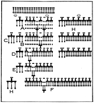
FIGURE 178.
The stage lighting is usually divided into four groups, viz.: three color groups and a group of stage pockets. The number of white lights is usually equal to that of all of the colors.
Figure 178 shows a well laid out switchboard. All of the lights in the auditorium are controlled by switches shown in the upper right-hand corner and all of these are under the control of the main switch. The house lights are usually thrown on or off as a whole and this main switch must be convenient for the operator.
The stage pockets are controlled by the bank of switches shown at E. Lights burning off the stage pockets generally are controlled by special operators on the stage or by actors, and need not be so very convenient to the switchboard operator. They must, however, be under his control when necessary; but here also a main switch is not advisable.
In addition to the three groups of lights spoken of above, there are a number of lights which should be controlled from the switchboard but must be so connected that they will be left on, no matter what is done with either house or stage light.
In this group belong a few lights mounted at the top of the switchboard which enable the operator to see his switches when all else is dark. These lights are generally shielded so as to throw no light in the direction of the stage opening. The orchestra lights also belong in this group, but a special switch may, with advantage, be arranged on this circuit to bring it under the control of one of the musicians. In some dark scenes these lights are turned out for a short time, but it is very important that they be turned on again at the proper moment, and this is more certainly assured, by giving the musicians control, than by leaving it to an electrician on the stage who may be very busy with other matters at the time.
The lights on the fly floor and in the rigging loft, as well as those in dressing rooms and basement, must also be independent. Fan motor circuits should also be independent of the house circuit. They are often needed when the house lights are thrown off.
With the switchboard illustrated in Figure 178 we have shown only the switches governing the house and stage proper. The switches governing the other lights are usually worked into the vacant spaces between the two groups. Each switch should be labeled in such a manner that a new operator can learn the board easily.
The most important part of the board is that part governing the stage lighting, and this should always be placed as conveniently as possible to the operator. A stage switchboard is like a house in that no one is wholly satisfied with the one he has, but thinks he could improve it a little if he could build it over again. The arrangement shown in Figure 178 is, however, quite satisfactory for general purposes. The white lights predominate in the ratio of two to one and are laid out in two groups A and B. Both groups are controlled by the switch C. The switches A and B do not control the lights at all if the smaller throw-over switches at the right are thrown downward. A diagram of these switch connections is given in Figure 179 where the switches B and C are indicated. The object of the switches A and B is to help in quickly increasing or decreasing the illumination on the stage. If in the beginning of a certain scene, for instance, only a small quantity of light is wanted, while a little later full illumination is desired, the low illumination may be obtained by throwing the proper switches down; the additional illumination which will be needed a few minutes later may be prepared for by setting the other switches needed to the upward position and at the proper moment closing switch B; this will instantly produce the effect which otherwise would be possible only by operating a number of switches in succession. In the same way, by a reversal of this process, the illumination may be reduced in any amount. This feature is very valuable in many stage settings.
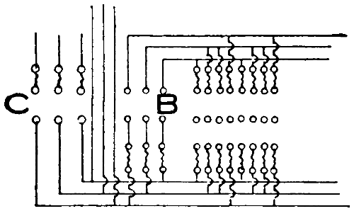
FIGURE 179.
To throw off all of the white lights the switch C must be opened. The switches D and F are main switches controlling colored lamps. All lamps of one color should be connected to one or the other of these groups unless some special color effect is desired.
From the three groups of switches, circuits extend into the foot lights, into every border, and into the proscenium side-light strips so that the color scheme may be carried out in any of these.
The handles of all switches in a row should be of the same height so that the operator may more readily accustom himself to catch them quickly. It is better to have switches of some excess capacity, as the heavy metal stands the arcing much better.
A main switch by which the whole board may be cut off should be installed but this need not be on the front of the board.