GENERAL CONSTRUCTION OF THE AQUEDUCT.
Reading edition
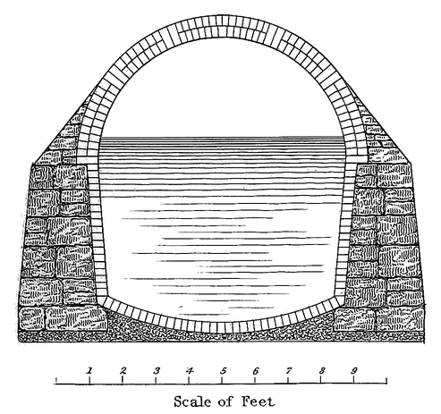
Plate I. is a section of the Aqueduct showing the form of the masonry used in earth excavations. The foundation is formed with concrete; the side walls of stone; the bottom and sides of the interior being faced with brick, and the top covered with an arch of brick.
In forming the concrete a mortar is made by mixing three parts of sand with one of hydraulic lime, and then mixing about three parts of stone, broken to a size allowing them to pass through a ring an inch and a half in diameter. Having thoroughly mingled the broken stone and mortar, the concrete is placed in its proper position and form, and brought into a compact state by using a pounder; and is then suffered to remain until it set, or become indurated, before any work is commenced upon it. The object should be to mix as many stones or pebbles as will thoroughly bed in the mortar, allowing none of them to come in contact, but all to be enveloped in mortar. This forms a body which becomes indurated and makes a foundation under the whole length of the Aqueduct like one continuous stone. It attains a degree of hardness which gives it the appearance of the conglomerate bearing the name of Pudding-stone, and is an article of the greatest importance in forming foundations for walls of great weight; superseding in many instances, where the soil is soft, the use of piles or other timber foundation.
Though we have evidence that concrete was used by the Ancient Romans in the foundations of some of their structures and even in the formation of their roads—such as the Appian-Way, and though we find it used in the foundations of the feudal castles of the Norman Barons of England, still it has not been introduced into the general practice of architecture until quite a modern date, and even at the present time is not widely appreciated in this country as a material of so much importance in foundations.
The side walls are laid up in a character of workmanship styled “rough-hammered work;” the stone required to be of sound and durable quality and laid in a manner to render the work water-tight. Though attention is given in some degree to insure a proper bond to the wall, yet the point more particularly attended to, is to make it compact and impervious to water. The bonding of the wall is not by any means disregarded, in all situations where it is required, yet the position of the work generally, where it is in excavation below the natural surface of the ground, renders such precaution of less importance than that of making it compact. The mortar used in these side walls is formed by mixing clean sharp sand with hydraulic lime, using the proportions of three parts of the sand to one of the lime; and these are thoroughly mixed and incorporated before they are wet; when this mixture is wet and thoroughly worked, it is used immediately and always kept properly tempered so as to render it plastic, and to prevent any disposition to become hardened before it is in the wall. After the side walls are finished and the concrete between them has received its proper form, a coating of plastering, about three eighths of an inch in thickness, is put on over the surface of the concrete and on the face of the walls before the interior facing of brick is commenced. The proportions of this plastering are two parts of sand to one of the hydraulic lime.
The bricks used in this work are generally of quite a different character from those used in ordinary house-building; being harder burnt and of a superior quality of material. They are required to be burnt to such a degree of hardness that they present a cherry red, or brownish color, and give a clear ringing sound when struck; and when broken, must present a compact and uniform texture. All bricks brought upon the work which are soft and of a pale color, such as are usually denominated salmon brick, are rejected. Those which are used, possess nearly the hardness and durability of ordinary building stone, and are calculated to resist the action of the water, to which they will be exposed.
The advantage of using brick is, that a smooth channel offering little resistance to the flow of water can be formed with less expense than with stone, and greater security can be obtained against any leakage; for besides the coat of plastering which covers the face of the walls and the top of the concrete, there is also a mortar joint between this plastering and the brick work. The bricks being of good form and easily handled, can be more expeditiously and closely laid than the face of a wall of stone, and afford a smooth and uniform face to the wall with less expense. They are required to be bedded full and flush with mortar, so that on lifting one from its position in the work, no imperfections be discovered, but the impress of the brick be found distinct throughout.
The proportions of the mortar for the brick work, are two parts of sand to one of hydraulic lime.
The inverted arch of brick, as well as the brick facing on the sides, is four inches thick, and the roofing arch of brick is eight inches thick.
After the masonry is finished the excavation which was done to receive it, is filled up around it, and over the top of the roofing arch generally to the height of 3 to 4 feet, and in some instances of deep excavation, up to the natural surface. If the natural surface be not of sufficient height for the top of the earth covering, the earth is raised to the requisite height with proper width on the top and slopes on the sides for protection to the Aqueduct masonry.
I
F. B. Tower.
Gimber.
II
F. B. Tower.
Gimber.
III
F. B. Tower.
Gimber.
IV
F. B. Tower.
Gimber.
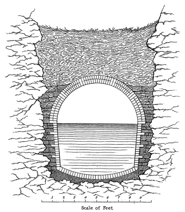
Plate II. is a section of the Aqueduct in open cutting in rock.
After the rock has been excavated to the required depth and width, the bottom is levelled up with concrete to the proper height and form for the inverted arch of brick, which is laid in the manner before described for earth excavation. The side walls of stone and brick are bonded together by headers of brick entering the stone walls as shown in the drawing, and the walls of stone are built closely against the sides of the rock and forming a junction with it. On the exterior of the roofing arch a heavy spandrel of stone masonry (of the same character as the stone walls beneath it) is built, filling the space between the arch and the rock. After the masonry is finished, the rock cut above it is filled with earth to the same height above the roofing arch as mentioned for earth excavation.
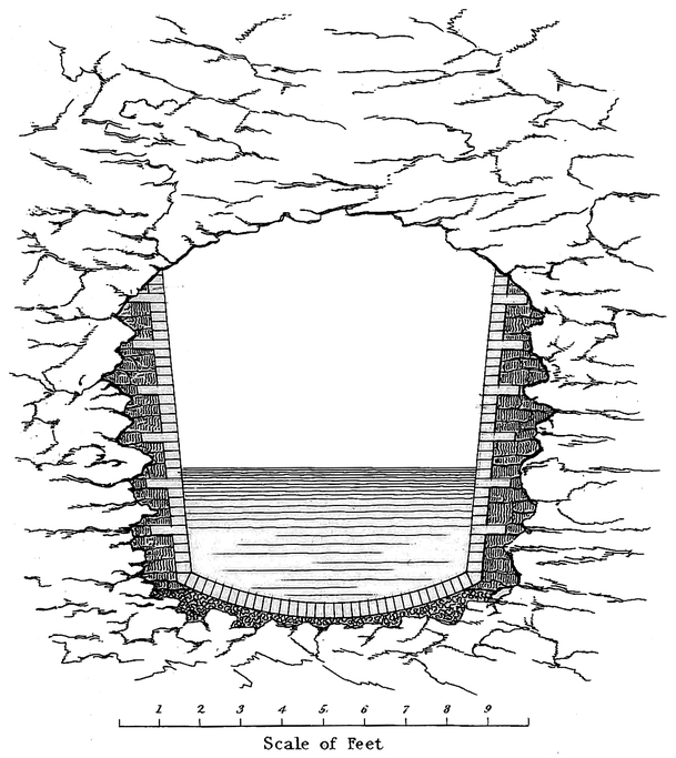
Plate III. is a section of the Aqueduct in tunnel cutting in rock.
The width of the tunnel excavation in rock is the same as that of open excavation in rock; and the manner of building the masonry to form the channel-way is the same, with the exception that the rock roof of the tunnel serves as the roof of the channel-way, where it is sound, but in cases where the rock is soft and liable to fall, a brick arch is built over the channel-way, and the space between its extrados, or outer surface, and the rock roof is filled with earth closely rammed in. In some instances where the tunnel perforated rock which was at first quite hard, the roofing has by exposure to the air, become soft and insecure, so as to render it necessary to turn an arch for its support. This is attended with inconvenience and some difficulty after the channel-way has been completed and closed through the tunnel.
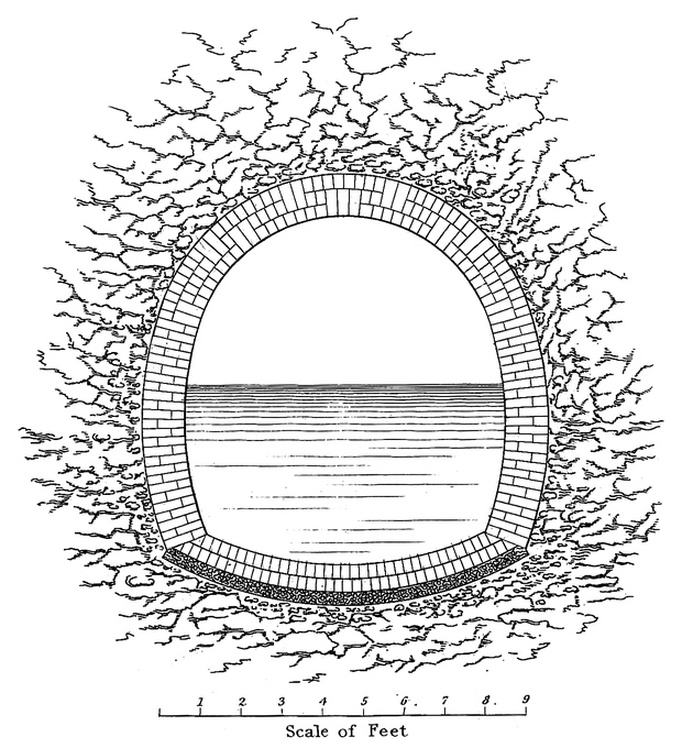
Plate IV. is a section of the Aqueduct in tunnel cutting in earth.
When the earth is dry and compact, the excavation for the bottom and sides is made of a proper form to receive the masonry, which is built closely against it: the top is excavated sufficiently high to give room to turn the arch, and the space above is afterwards filled with earth closely rammed in. Where the earth is wet and there is difficulty in making it stand, the excavation is made larger, and props of timber and plank are used to support the top and sides until the masonry be completed; and the whole space exterior to the masonry is then compactly filled with earth.
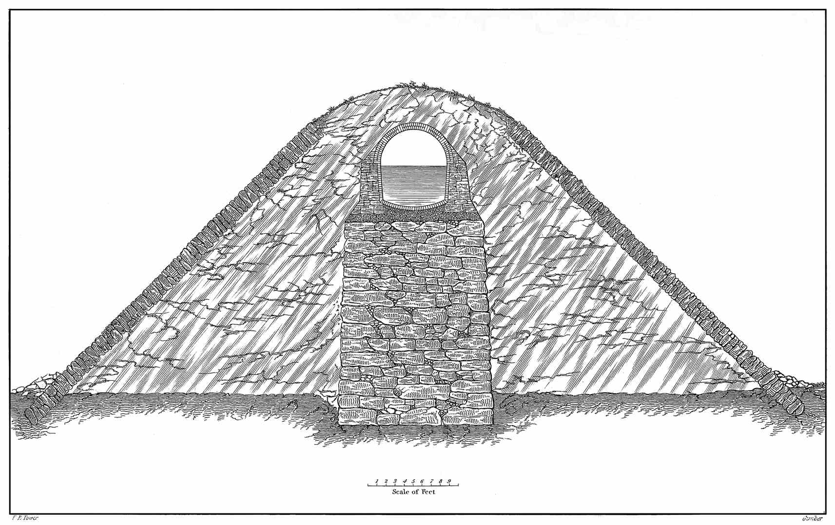
Plate V. is a section of the Aqueduct showing the manner of constructing it across valleys, or where the natural surface of the ground falls below the plane of grade.
In such cases the Aqueduct is supported upon a foundation wall of stone laid dry, and formed by using large stones laid in positions to give proper bond, and to allow small broken stone to be closely packed in, filling up all the interstices so as to form a compact and uniform mass. The wall is generally allowed to stand some months after it is completed, before the masonry of the Aqueduct is commenced upon it, lest by this weight being placed upon it before it has found its bearing, it should settle and cause cracks in the masonry. That such settlement should in some instances occur, even after the Aqueduct is completed, is not surprising, for passing over so many different elevations, and encountering such numerous transitions from a hard soil, or from rock, to valleys of alluvial deposit, it would be beyond human powers of foresight and vigilance to prevent it.
V
F. B. Tower.
Gimber.
To render the Aqueduct more secure in such positions, the concrete foundation has an increased thickness, and in preparing it a greater proportion of hydraulic lime is used; the proportion being two and a half parts of sand to one of lime. The dimensions of the stone side walls and the spandrel backing of the roofing arch, are also increased; and the proportion of hydraulic lime to the sand in the mortar for these is increased. Another precaution has been taken to render the work secure, by plastering the interior of the Aqueduct over these foundation walls. The embankment adjacent to foundation walls has various slopes according to circumstances, and is generally protected with a dry stone wall on the face, and is carried up of sufficient width to insure the requisite covering over the Aqueduct masonry.
Along side hills an excavation is made for the Aqueduct into the hill, and a protection wall of stone built on the lower side so as to support a covering of earth over the masonry; great care being taken to obtain a deep and firm footing for this wall in order to render the work secure. In such a position the Aqueduct is perhaps less secure than in those before described. Where the soil is wet from springs, and the formation clay, there is danger of slides; and in rainy seasons there is danger from the torrents which gather on the hill sides and come down with destructive force: the earth covering is liable to be carried away, and the Aqueduct itself to be undermined. Great care has, however, been used in such cases to form strong paved channels for the passage of the water over the top of the Aqueduct, or by culverts to pass it underneath.
WASTE-WEIRS.
At suitable places on the line of the Aqueduct, waste-weirs are constructed to discharge surplus water. They are constructed in one side of the channel-way, in such manner as to allow the water to flow off when it rises above a given level, and arrangements are also made at these places to close the channel-way entirely, by means of stop planks, and to discharge the whole of the water through waste-gates; so that the water might be running from the Fountain Reservoir through a portion of the Aqueduct and discharging from these waste-weirs while the remainder of the channel-way, or portions of it, would be drained so as to admit of inspection or repairs. There are six of these waste-weirs constructed for the Aqueduct.
VENTILATORS.
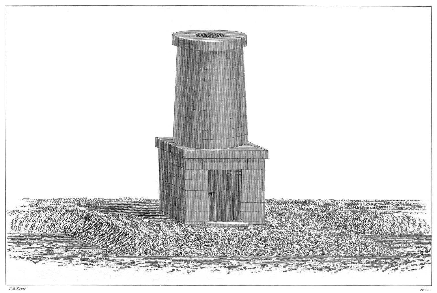
For the purpose of ventilation hollow cylinders of stone are erected over the top of the Aqueduct and rising about 14 feet above the surface of the ground, or earth covering. These occur every mile, and every third one is constructed with a door to afford an entrance to the Aqueduct.
Those allowing an entrance have an interior diameter of 4 feet, and the others have an interior diameter of 2 feet; each, however, slightly diminishing towards the top. An iron grating covers the top to prevent any thing being thrown in.
Plate VI. is a view of an entrance ventilator; this stands on one side of the Aqueduct, where the masonry of the side wall is enlarged for its base; we can descend from the door and gain an entrance to the channel-way by an opening in the side of the roofing arch. The sill of the door is about 12 feet above the bottom of the channel-way.
VI
F. B. Tower.
Gimber.
ENTRANCE VENTILATOR
Those not intended for an entrance stand directly over the top of the Aqueduct and are groined into the roofing arch.
Besides these Ventilators, there are openings 2 feet square in the top of the roofing arch, every quarter of a mile: they are covered with a flag stone and the place is marked by a small stone monument projecting above the surface of the ground. These may be useful to obtain entrance to the Aqueduct, or to afford increased ventilation should it ever become necessary.
CULVERTS.
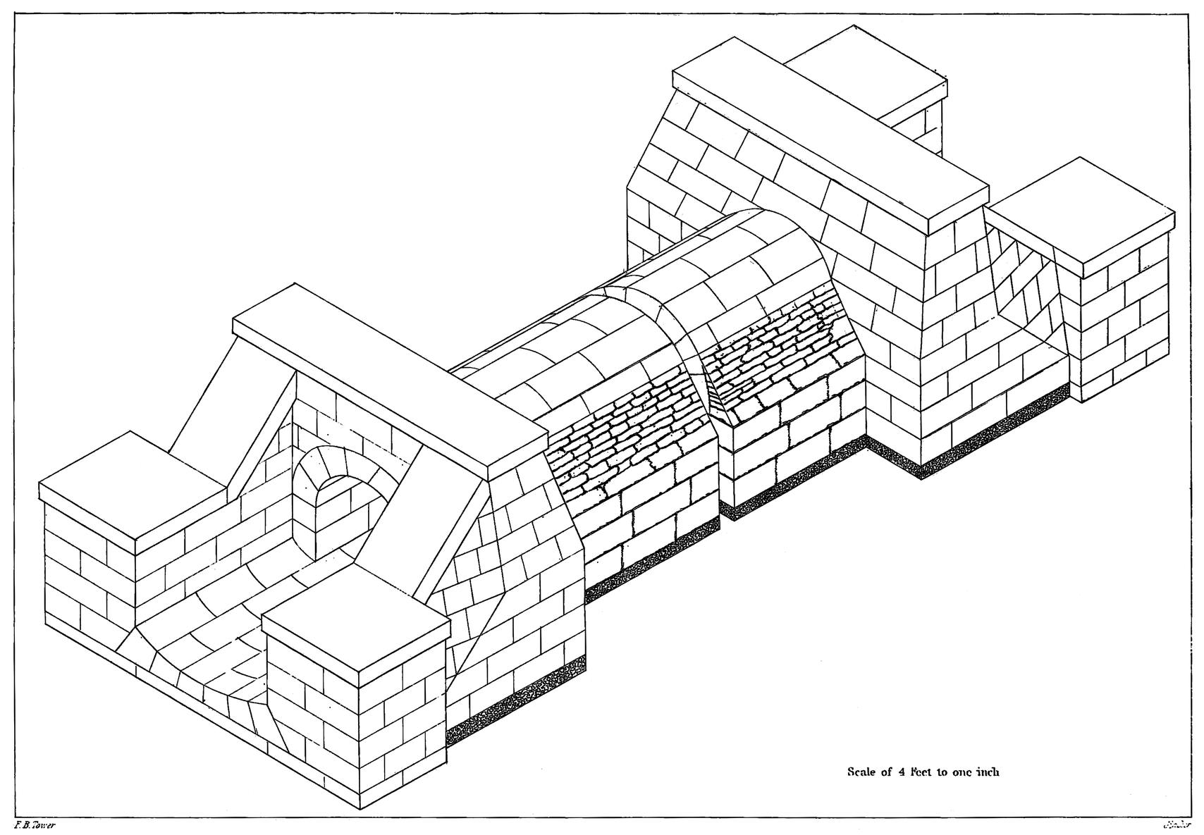
Where streams intersect the line of Aqueduct, culverts are built to allow them to pass under it. They are simply a stone channel-way built under the Aqueduct of such form and dimensions as will allow the stream to pursue its natural direction without causing injury to the work. The foundation of these culverts is formed by laying down concrete, upon which an inverted arch of cut stone is laid forming the bottom of the water-way: side walls of stone are built and surmounted by an arch of stone. The span, or width of water way, of the culverts built, varies from 1½ foot to 25 feet. Those of 1½ foot span have a square form for the water-way, and are constructed by making a foundation of concrete, upon which a flooring of well dressed stone is laid forming the bottom of the water-way, and from this, side walls are built and covered by a course of thick stone flagging well dressed and closely fitted. At each end of the culvert a deep wall is built underneath so as to prevent the water from doing injury by undermining it. Buttresses and wing walls are built at each end of the culvert to guide the water to and from the channel-way, and a parapet wall is built over the top of the channel-way at each end to sustain the embankment of earth over the culvert. These wing walls and parapets have various forms; sometimes the parapet is built across the top of the culvert, and the wing walls built at right angles to it, and sloping down to the buttresses, and sometimes the wing walls and parapet form one continuous wall of a semi-circular form, the top sloping up from the buttresses in a plane parallel with the slope of the embankment covering the Aqueduct above. These culverts are permanently constructed, and in preparing the plans for them much skill has been displayed in adapting the form and size which the circumstances required, and much taste displayed in the design for their construction.
Plate VII. is an isometrical drawing of one of the culverts with rectangular wings and parapets; the body of the culvert is cut in two in the drawing, showing that it may be of any length, according to the width of the embankment through which it is constructed. The length is generally arranged so that the slope of the embankment may intersect the rear of the top of the parapet and pursue a direction down, parallel with the slope of the top of the wing walls.
VII
Scale of 4 feet to one inch
F. B. Tower.
Gimber.
Gate Chamber at the Head of the Aqueduct and Grade of the Water-way of the Aqueduct.
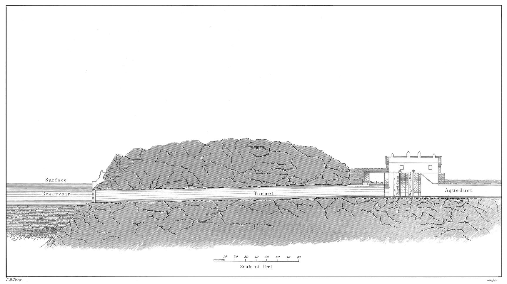
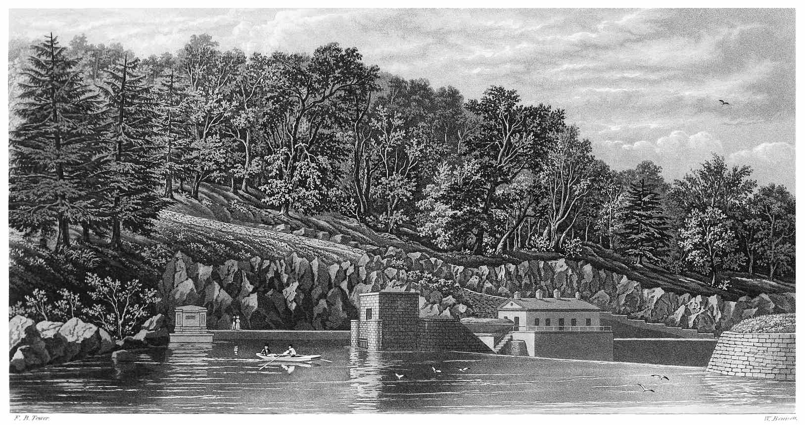
Plate VIII. is a longitudinal section through the tunnel and gate chamber at the head of the Aqueduct showing its connection with the Fountain Reservoir. This gate chamber is not in any way connected with the dam itself, but stands some distance from it, and the water reaches it by means of the tunnel which leaves the Reservoir above the dam and passes through the solid rock of the hill against which the masonry of the dam is built, a distance of over 200 feet. This tunnel descends into the Reservoir, so that the centre of it at the mouth is about 12 feet below the surface of the water; any floating substance cannot enter it, and during the winter season when the water is frozen over no obstruction can take place to the flow into the Aqueduct, and during the summer season the water will be drawn from a level where it is cooler than at the surface.
The gate chamber has two ranges, or sets of gates; one called regulating gates, and the other guard gates: the regulating gates are made of gun metal, and work in frames of the same material which are fitted to stone jambs and lintels: the guard gates are made of cast iron, and work in cast iron frames also attached to stone jambs and lintels. The gates are all managed by means of wrought iron rods attached to them, having a screw formed on the upper part on which a brass nut works, being set in a cast iron socket-cap.
The bottom of the water way, of the Aqueduct, where it leaves the gate chamber is 11.40 feet below the surface of the Fountain Reservoir, and 154.77 feet above the level of mean tide at the city of New-York. The following table shows the length of the Aqueduct as it is divided into different planes of descent, from the gate chamber at the Croton dam to the gate chamber at the Receiving Reservoir on the Island of New-York. Commencing at the south side of the gate chamber at the Croton dam,
The 1st plane of Aqueduct extends 26099.72 ft. or 4.943 miles, and the descent 2.94 ft.
The 2d plane of Aqueduct extends 148121.25 ft. or 28.053 miles, 30.69 ft.
Length of pipes across Har. River, 1377.33 ft. or 0.261 miles.
Diff. of level betw’n extremes of pipes 2.29 ft.
The 3d plane of Aqueduct extends 10733.14 ft. or 2.033 miles, 2.25 ft.
Length of pipes across Manhat. valley, 4105.09 ft. or 0.777 miles.
Diff. of level betw’n extremes of pipes 3.86 ft.
The 4th plane of Aqueduct extends 10680.89 ft. or 2.023 1.60 ft.
201117.42 ft. — 38.090 miles 43.63 ft.
Making the whole distance from the gate chamber at the Croton dam to the gate chamber at the Receiving Reservoir 201117.42 feet, or 38.09 miles, and the whole descent 43.63 feet.
The descent on the first plane is about 7⅛ inches per mile.
The descent on the second and third plane is about 13¼ inches per mile.
The descent on the fourth plane is about 9½ inches per mile.
In crossing Harlem River there is a fall of 2 feet more than there would have been had the Aqueduct continued across with its regular inclination: this extra fall will afford an opportunity to adjust the number and capacity of the pipes (which descend below the level of the Aqueduct and rise again) to discharge the full quantity of water as freely as the Aqueduct, or channel-way of masonry, would have done had it continued its regular inclination across the valley.
In crossing Manhattan Valley there is an extra fall of 3 feet for the same reasons as before stated for that at Harlem River. In both cases, by using the pipes, there is a loss of the head of water for the City Reservoirs, equal to the amount of this extra fall; but this small loss of head was not considered of such importance as to induce the building of structures across these valleys up to the plane of Aqueduct grade.
VIII
F. B. Tower.
Gimber.
The bottom of the water-way of the Aqueduct at the gate chamber where it enters the Receiving Reservoir, is 7.86 feet below the level of top water line in the Reservoir, thus when the Reservoir is full the water will rise to within 7¼ inches of the top of the interior of the Aqueduct at that place, and the height from top water to the top of the interior will increase, going northward according to the inclination of the plane of Aqueduct grade, until it reach the surface level of the flow of water in the Aqueduct.
The height of the interior of the Aqueduct is 8 feet 5½ inches, and the greatest width is 7 feet 5 inches. The sectional area of the interior is 53.34 square feet. On the first plane, the Aqueduct is larger; being 2.05 feet higher at the gate chamber, 2.31 feet higher at 2244. feet from the chamber, and then diminishing, to the head of the second plane, where it assumes the size above mentioned and continues of that size throughout the remainder except in tunnels, where it assumes the forms before described. Where the Aqueduct on the first plane is larger, the width across the interior at the spring line of the roofing arch is the same as the general width, but the increase takes place only in the height of the side walls, and the slope of the inner face of the walls being the same, the width across at the spring line of the inverted arch will be less according to the increased height of walls. The original design was to continue the inclination which the second plane has, up to the Fountain Reservoir; but it was considered desirable to draw from this Reservoir at a lower level, and the head of the Aqueduct was depressed for that purpose, and a less inclination adopted for the length of the first plane. The roofing arch was left on the same inclination as was originally designed, except for the distance of 2244. feet from the gate chamber, where it was built on a level.
The curves which are used to change the direction of the line of the Aqueduct are generally formed with a radius of 500 feet; some have a radius of 1000 feet, and in a few instances larger ones are adopted, but the majority of them are of 500 feet radius.
The velocity of the water in the Aqueduct has been ascertained to be about one mile and a half an hour when it is 2 feet deep; this was determined by floating billets of wood from the Croton Dam to Harlem River and noting the time of their passage. Such an experiment would express the surface velocity and would give a greater velocity than it would be proper to attribute to the whole body of water in the Aqueduct; but the depth of water in the Aqueduct will be probably 4 feet as soon as it is brought into general use, and then there will be a corresponding increase in the velocity of the body of water. This velocity of a mile and a half an hour may be taken in general terms as the velocity of the water in the Aqueduct.
IX
F. B. Tower.
W. Bennett.
VIEW ABOVE THE CROTON DAM.