CONTENTS (continued 2)
Reading edition
Slope carriages usually have the tracks running crosswise so that the car is pushed on from the side instead of from the end.
SKIPS, OR GUNBOATS
17. Skips are self-dumping cars used for hoisting material from shafts or slopes. In a vertical shaft, they run in guide tracks; but in a slope they have wheels and run on a track like a car. In the anthracite region of Pennsylvania, skips are called gunboats.
As the skip is not detached from the hoisting rope, time is saved at the top over that needed to unhook and hook the cars to the rope or to remove and place the cars on the cage. But since dumping the material into the skip and again on the surface produces considerable fine material, skips, or gunboats, are seldom used for any material, such as coal, that is often lessened in value by being broken. The skip, or gunboat, shown in Fig. 14 is closed along the top a and open at the end b, which is cut at about the angle of the slope in which it is to be used, so as to remain practically level during the hoist. It is made of sheet iron, the bottom, sides, and top being stiffened by angle or T irons, and the back stiffened and protected by 3-inch planks, backed by 3" × 6" timbers. The wheels of a skip are fixed on the axles, which run in journal boxes, thus insuring smoother running than is obtained with loose wheels. The details of the journal bearings, as shown in Fig. 15, consist of three castings, the bracket a, which is bolted or riveted to the gunboat, a pivot casting b, and the bearing proper c. The bearing c rests on the axle and carries, by means of trunnions d, the pivot casting b, on the top of which is placed a rubber cushion e to lessen the shocks between the casting and the bracket.
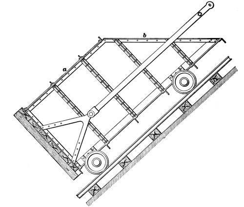
Fig. 14
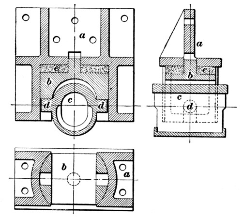
Fig. 15
18. Method of Loading Skips.—In Fig. 16, a skip a is shown in a slope standing immediately below a level where a car b is ready to have its load dumped into the skip. Instead of dumping the mine car directly into the skip, a bin is frequently provided at the level station, or landing, into which the mine cars are dumped and from which the material is loaded into the skip through suitable chutes. The use of such bins makes the hoisting of material largely independent of the working conditions on the levels and the hoisting can be more systematically and satisfactorily carried on.
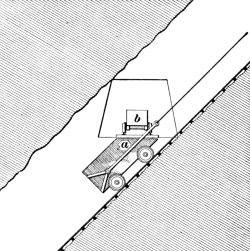
Fig. 16
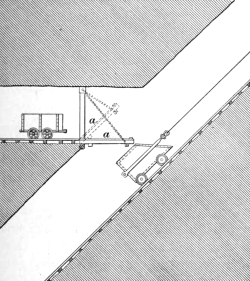
Fig. 17
If the material comes to the slope as shown in Fig. 17, it is necessary to let down a bridge a, on which the car runs, in order to reach the skip. After the car is dumped, the bridge is lifted out of the way into the dotted position, so as to leave the slope unobstructed.
19. Method of Dumping Skips. To dump a skip at the surface, the tracks are extended above the slope mouth, as shown in Figs. 18 and 19, and are arranged so that the material may be dumped directly into a bin or into cars as desired.
In the arrangement shown in Fig. 18, the front wheel of the skip strikes a stop a and, since the bail of the skip is pivoted far down toward the lower end, as the rope continues to pull, the rear of the skip is raised and the material is dumped. The objection to this method is that if the rope is slightly overwound the skip is pulled off the track and does not then right itself on the track when the rope is released.
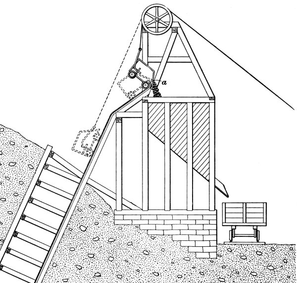
Fig. 18
In the Lake Superior iron and copper region, many of the dumps are built as shown in Fig. 19. In this dump, the rails of the main track a are curved as shown at b; a short distance back of the beginning of this curve, another track c begins outside the track a and runs in a straight line parallel to the inclination of the hoist. The track c is of a wider gauge than a, and the rear wheels of the skip have a wider tread than the front, so that they will run on c while the front wheels take the curved track until they strike the stop d. The rear of the skip will thus be raised and the material dumped. There are but two tracks in the main part of the slope.
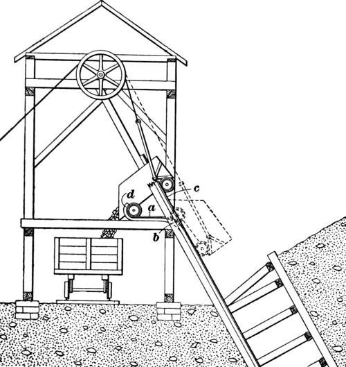
Fig. 19
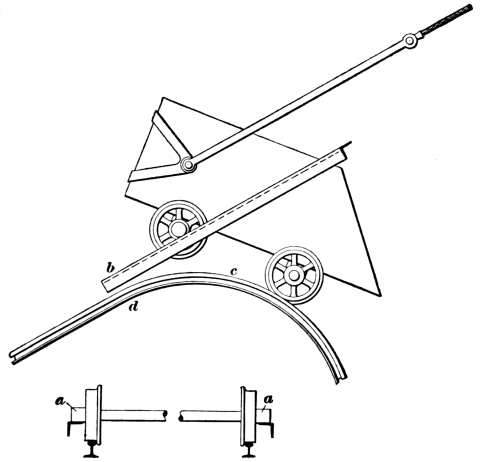
Fig. 20
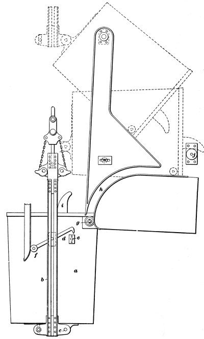
Fig. 21
In the method illustrated in Fig. 20, the rear and front wheels have the same tread, but the rear axle is longer than the front and has rollers a on each side. These strike the track b, and while the front wheels follow the curved track c these rollers run on the track b and thus raise the rear end of the skip.
20. Skip Cage.—Where a self-dumping skip is to be used in a vertical or highly inclined shaft and it is desired to use safety catches, the skip a is mounted in a cage or frame b, Fig. 21, similar to the self-dumping cage, Fig. 11. The skip being pivoted at c one side of the center, and resting on the frame of the cage, tends to remain upright until it reaches the dump; but for safety it is sometimes locked in place by the latch d, which hooks over the pin e. When near the top, the roller f on the end of the latch d comes in contact with a bar that depresses the roller and thus unhooks the latch. The roller g enters and travels along the guide rails h, tipping the skip. There are two rollers g, one on either side of the skip. The nose i is temporarily caught on the roller j, thus stopping the movement of the skip sidewise and away from the upright guide.
BUCKETS
21. Buckets, such as are used for hoisting material during shaft sinking, are continued in use after mining begins when the amount of material to be hoisted is small.
CAR LOCKS
22. Several methods of keeping the car on the cage have already been illustrated: by chains, Fig. 8; by bails, Figs. 9, 10, and 12; by omitting sections of the rail under the car wheels, Fig. 11; and by dropping a portion of the platform, Fig. 13. A very common way is merely to put a pin through the hole in the drawbar and into the floor of the cage. Another common device consists of a brake block that fits between the wheels and can be thrown in from the side by a lever when the car is in place. Another device consists of a yoke, which, by means of a lever, is raised when the car is in place so that it passes about the axle and thus holds the car. A device frequently used on self-dumping cages is shown in Fig. 22.
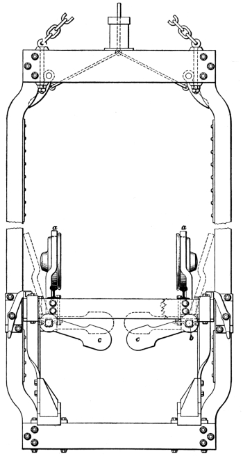
Fig. 22
The curved bars a of iron, which just fit around the car wheels as shown, are attached to the loose bars b, on the ends of which are the weights c. When the cage is at the bottom, these weights strike on a cross-piece and are raised to the position shown by the dotted lines, throwing out the bars b, as shown by the dotted line, thus releasing the wheels. The devices shown in Figs. 11, 13, and 22 do not come into action until the cage leaves the landing and the cars must, therefore, be watched until that time.
CAGE GUIDES
23. Guides are used in all vertical shafts of any considerable depth and in many highly inclined shafts to keep the cage from swinging about and striking the sides of the shaft. They are made of wooden rails, iron rails, or wire ropes. In American mines, timber guides predominate, although some iron ones are used, and for small shafts at ore mines wire-rope guides are common. In English mines, wire ropes, called conductors, are very largely used. This difference in practice is probably due to the fact that in English mines the shafts are usually round and the cages are rectangular. In such a shaft, the wire-rope conductors hang from the head-frame without any cross-bracing, but they require a strong support, as both the weight of the ropes and the strain to give the necessary tension come on the head-frame. When both the shaft and the cage are rectangular, as in most American mines, timber guides are easily put in and they offer a good surface for the safety catches to grip.
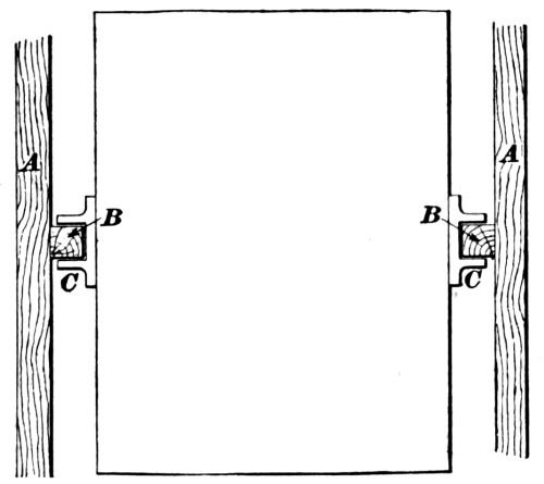
Fig. 23
Wooden guides are always rectangular in cross-section and in the United States are usually made of yellow pine or other long-grained wood that does not splinter easily; in some localities, oak or some of the other harder woods are used. There is no fixed size for cage guides, but 4" × 4", 6" × 8", 8" × 10", and 4¼" × 11" timbers are frequently used.
The guides are firmly fastened to the shaft buntons with lagscrews or with bolts countersunk into the guide so as to be clear of the shoes, and, to secure safety with speed in hoisting, the ends of the guides must be put together with joints that are not liable to displacement and that offer no projections to the shoes in passing. The buntons to which the guides are secured must be so firmly fastened that they cannot get out of place, and the guides must be set as nearly as possible in a straight line, because if they are crooked the cage is thrown back and forth as it travels along them and this not only increases the strain on the hoisting rope and engine, but sooner or later loosens and misplaces the guide. Fig. 23 shows a plan of a cage with the bunton A, guides B, and cage shoes C in their normal positions.
LANDING FANS OR KEEPS
24. In order to take the strain off the hoisting rope while a cage or skip is being loaded or unloaded, a mechanism to support the cage is placed at the top and at any level of the mine where loading is done, excepting at the bottom level where all that is usually required are the cross-timbers for the cage to rest on. These supports have different names in various localities, being known as fans, keeps, cage rests, landing dogs, landing chairs, wings, etc. Their use increases the safety of caging.
25. A common form of keeps is shown in Fig. 24. The cage a rests on four square bars of iron b, one under each corner of the cage. These bars have an eye or hub at the lower end and are keyed to the shafts d, which rest in cast-steel boxes. The levers e and f, which are also keyed to the ends of the shafts d, are connected by a rod g. Chains h prevent the fans from moving too far under the cage. When the cage is to be lowered, it is first lifted clear of the fans and the lever e is moved into the dotted position, thus moving the fans b out of the way and permitting the cage to be lowered. The inside of the fans have no projections, and the operating mechanism is such that no harm would come if they were left in the shaft and a hoist were made, as the cage would open out the fans and pass through them without any trouble. If, however, the fans are not drawn back at all the headings in the shaft when the cage is lowered, great damage results when the cage strikes the projecting fans. To avoid the possibility of such an accident, fans have been devised that fall back out of line of the shaft as soon as the weight of the cage is removed from them.
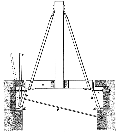
Fig. 24
26. Hydrostatic Fans.—Most fans in use are built on the same principle as those just described, although the details of their construction may vary. An objection that can be raised against them is that, with large cages and heavy loads, the jar caused by letting the cage down on such a rigid support is very hard on the cage. All cages, particularly heavy ones, suffer much more wear from being landed too suddenly than from the strains of hoisting. For this reason, it is advisable to make the upper parts as light as compatible with strength and the side pieces stronger than needed for the actual strains to which they are subjected. Hydraulic fans, Fig. 25, have successfully overcome this trouble. The cylinder shown is one of four on which the cage rests. The eye at the lower end fits on a bar by means of which the cylinders are moved backwards and forwards similar to the motion of the fans b, Fig. 24. In Fig. 25 (a), the cage is shown as about to rest on the jaw a. As the cage settles, it pushes the plunger b downwards, but this action is resisted by oil in the cylinder at c. At first, this resistance is very slight, because the V-shaped grooves d in the plunger, which are of considerable size at the end of the plunger, allow the oil to escape freely into the upper chamber e. These grooves, however, taper down to nothing, so that the flow of oil through them decreases until none can pass except by leakage around the plunger. This allows the plunger with its load to settle slowly to the bottom, as shown in Fig. 25 (b).
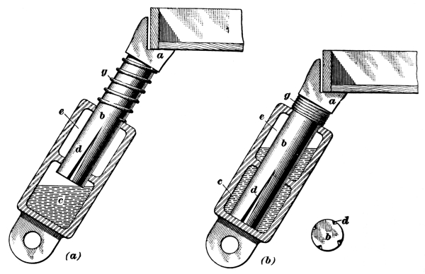
Fig. 25
If now the cage is lifted and the weight thus removed from the jaw a, the spring g pushes the plunger b outwards and allows the oil to run from e back into c.
27. Pneumatic Fans.—A pneumatic fan, shown in section in Fig. 26, is one in which the shock of the landing is partially relieved by a cushion of compressed air. The fan is keyed at the bottom to the shaft a that rotates it, as in Fig. 24. The cylinder b contains the plunger c, which is kept at the top limit of its motion by the spring d. When the cage lands in the jaw e, the plunger descends, compressing the air in the cylinder b. The air escapes slowly through the ¹/₁₆-inch hole f, thus allowing the cage to settle into place with very little shock. These fans should be made of wrought-iron or cast-steel so as not to be easily broken.
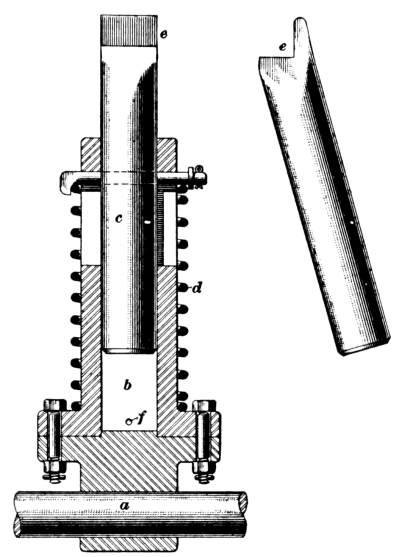
Fig. 26
28. Cage Chairs.—In the case of a cage required to stop at a large number of levels, it is expensive to provide fans at each level, and to obviate this a strong steel bar or dog may be used under each corner of the cage, all four bars being connected to a lever on the cage, by means of which they can be thrown out at will so as to rest on supports provided at each level. Fig. 27 shows Gray’s patent cage chair, which operates on this principle. The sliding bars a are connected by the cross-bars b, which are pivoted at the center and operated by the bar c through the links d. By moving the lever e into the position shown, the bars a are thrown out so as to rest in notches or on wall plates in the shaft. The springs f, through the cross-bars b, force the sliding bars a back under the cage when the lever e is released.
HEAD-FRAMES
29. A head-frame of wood, iron, or steel is built over a shaft or slope mouth to carry the sheaves over which the hoisting ropes are conducted from the mine to the drum of the hoisting engine; it also usually carries the upper portion of the cage guides or, in the case of a slope, the tracks for cars.
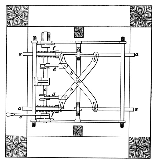
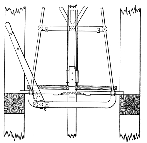
Fig. 27
A head-frame must be strong enough to bear the strain brought on it due to the total load hoisted and the pull of the engine in hoisting this load; it must also be rigid in construction to withstand the severe vibration and shock to which it is subjected on account of the rapid hoisting and the jar due to the landing of the cages.
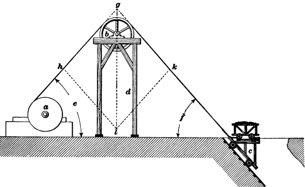
Fig. 28
The amount and direction of stresses that a head-frame must resist are usually determined by applying the parallelogram of forces as follows: Fig. 28 is a simple head-frame at a slope; a is the drum of the hoisting engine with the rope coming from its upper side and running over the head-sheave b down to the slope cage c. Assuming that the angles e, f made by the two portions of the rope with the horizontal are equal, and that the pull on each part of the rope is 20,000 pounds, to determine the amount and direction of the resultant of the two rope pulls, proceed as follows: Extend the rope lines to the point of intersection g and from there lay off the two lines g h and g k, to some definite scale, representing the pull of the rope. If a scale of 2,000 pounds to ⅒ inch is taken (⅒ inch = 2,000 pounds), g h and g k will each be 1 inch long. Complete the parallelogram by drawing h l parallel to g k and k l parallel to g h. The diagonal g l represents the direction and amount of the force acting on the head-frame due to the pull of the two portions of the rope. The diagonal, by measurement, is 1½ inches or ¹⁵/₁₀ inches long, and since each tenth inch equals 2,000 pounds, the stress on the head-frame in the line of the diagonal g l is 2,000 × 15 = 30,000 pounds. The figure also shows that the direction of this force is vertical, hence there is no tendency for the frame to be pulled over to either side and, theoretically, side bracing is not needed.
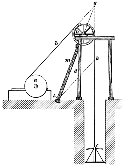
Fig. 29
30. Consider now the case of a vertical shaft, Fig. 29, in which, as before, a is the drum, b the head-sheave, c the cage, and d the head-frame, and assume the same pull of 20,000 pounds on each part of the rope. As before, extend the lines of the rope, which are the lines of force along which the pulls due to the engine and the load act, until they intersect at g. From this point lay off on these lines distances representing the stresses in the rope to any scale. Using the same scale as before, ⅒ inch = 2,000 pounds, the lines g h and g k representing the two forces will be each 1 inch long. Completing the parallelogram by drawing h l parallel to g k, and k l parallel to g h, and drawing the diagonal g l through g, the resultant, g l = ¹⁹/₁₀ inches, represents a stress of 38,000 pounds. The direction of the resultant is also determined, being in the line of the diagonal g l. If the head-frame shown in Fig. 28 were used for this case, it would be overturned by this resultant force, unless the leg on the opposite side of the shaft from the engine were securely anchored, so an inclined brace m is added to resist this overturning action. The resultant of all forces acting on the head-frame should generally fall within the structure if the greatest stability is to be secured, but when this cannot be done it is necessary to resist the overturning pull by anchoring the head-frame to its foundations much more securely than is the case where the resultant falls within the structure.
The direction of the resultant force may be obtained by drawing a line through the intersection of the lines of action of the forces at g and the center of the head-sheave b, as may be seen in Figs. 28 and 29.
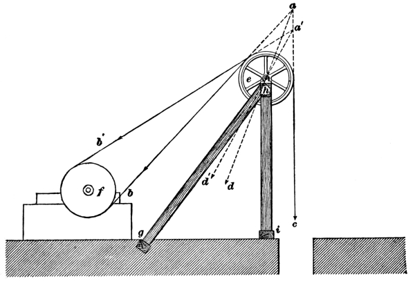
Fig. 30
31. In Figs. 28 and 29, the pull of one hoisting rope running from the top of the drum was considered, but in most cases it is necessary to consider the pull from two hoisting ropes, one running from the top and one from the bottom of the drum f, as shown in Fig. 30. a b and a′ b′ represent the directions of action of the two forces acting on the hoisting ropes, while the two vertical forces a c and a′ c acting down the shaft are approximately equal to the two forces acting toward the drum. There are, therefore, two resultants a d and a′ d′, the directions of which are determined by lines from a and a′ through the center of the sheave e. The amounts of these resultant forces can be determined by the parallelogram of forces as shown in Figs. 28 and 29. A resultant that is a mean between a d and a′ d′, both in position and amount, is sometimes taken, or the greater value as determined from a d or a′ d′ and the greatest inclination as given by a′ d′ may be used, as being the worst theoretical conditions to which the frame may be subjected. A head-frame usually has a vertical post approximately parallel to the vertical pull of the rope in the shaft, and an inclined member g h approximately parallel to the resultant determined by the parallelogram of forces. If g h, Fig. 30, is parallel to the resultant, the vertical leg h i is under no strain and merely supports the end of g h. If the resultant falls between g h and h i, both of these legs will be under compression. If the resultant falls outside of g h, the leg g h will be under compression and h i will be under tension. The head frame will be most stable when the resultant falls between g h and h i, but this cannot always be accomplished in building the frame on account of the conditions at the head of the shaft; nor is it always advisable to do so from structural considerations.
32. Since wood is much better adapted to withstand compressive than tensile stresses and since steel is adapted to withstand either tensile or compressive stresses, it is much more important that the members of timber frame conform as closely as possible to the theoretical line worked out in Figs. 28, 29, and 30 than in the case of a steel frame. Take, for instance, the case shown in Fig. 31, where for some local reason it is impossible to put an inclined strut in or near the line of the resultant stress to withstand the pull that tends to overturn the head-frame. In a steel structure, a can very easily be made a tension member by anchoring its lower end to a heavy foundation. This resists the tendency to overturn and makes a very stable structure. In practice, braces can generally be located parallel to the line of resultant strain, Fig. 29, or outside this line, as shown in Fig. 30, so that the strain due to the pull of the rope will come mainly on the inclined brace and not on the upright. To distribute the stress on the foot of the different parts of the frame, an inclined brace is usually set farther from the shaft than the parallelogram of forces locates it, and so placed that about two-thirds of the strain due to the pull of the rope comes on the brace and one-third on the upright parts of the frame. In order to give the frame a more stable base and because the base must be larger than the top of the frame to bring the foundations back from the shaft mouth, usually the members h i are also slightly inclined.
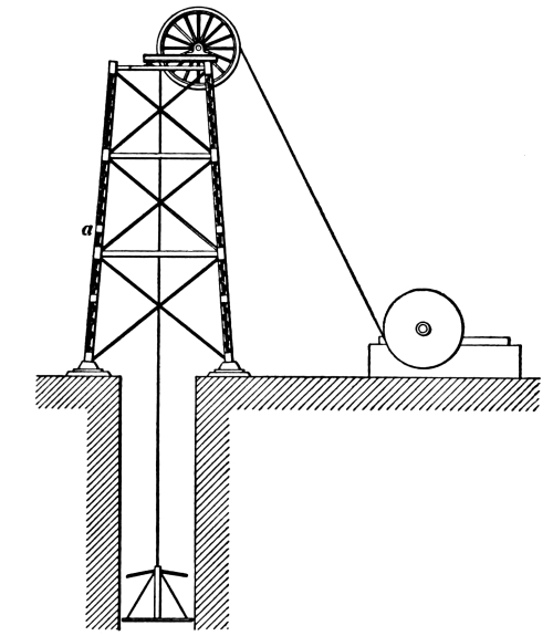
Fig. 31
Wherever permanency of head-frames is required, if steel is obtainable at a price at all comparable with wood, steel structures are being used, as timber frames rot.
TYPES OF HEAD-FRAMES
33. There are three types of head-frame construction—the A type, the square type without an inclined brace, and the square type with an inclined brace.
34. A Type of Head-Frame.—Fig. 32 shows the construction of a triangular, or A-shaped, head-frame of which (a) is a side elevation and (b) an end view. This particular frame is largely used at anthracite mines, but the type is one quite commonly used for timber frames, though the details of construction vary in different localities. The height of the frame is from 30 to 50 feet, and with direct-acting engines this height should be sufficient to allow a play of at least two-thirds of a revolution between the cage landing and the overwinding point. The posts a are parallel to the hoisting rope b as it hangs down the shaft and the inclined brace c, which resists any thrust that would tend to rotate the head-frame, is parallel to the resultant pull of the two parts of this rope b; the inclined braces d stiffen the frame and help support the cross-timbers m that support the cage guides e. The sills f are made of three pieces of timber 8 inches by 14 inches in cross-section. The posts a rest in cast-iron shoes g that are firmly bolted to the posts and sills. The inclined braces c, d are fitted with cast-iron shoes h, i. The post a and the two braces c, d are held in place at the top of the frame by the casting j, which also supports the pillow-block k.
The posts a and the brace c are made up of two pieces of timber each 8 inches by 14 inches in cross-section. The brace d consists of one piece of timber 8 inches by 14 inches in cross-section. The transverse braces l consist of two pieces of timber 6 inches by 14 inches in cross-section, bolted through the timbers a and c. The supports m for the guides are single pieces of 8" × 8" timber. The center post, as shown in Fig. 32 (b), is braced by the two pieces n, o, which are supported by two timbers p, q bolted to the two outside posts. The posts a and the inclined braces c are further braced by the tie-rods r, s, t, and u, all of which are fitted with turnbuckles, as shown at v. The different posts are firmly bolted together, the bolts being fitted with cast-iron washers.
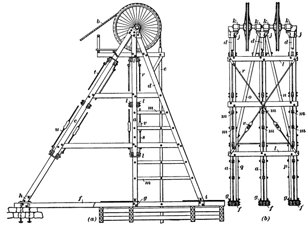
Fig. 32
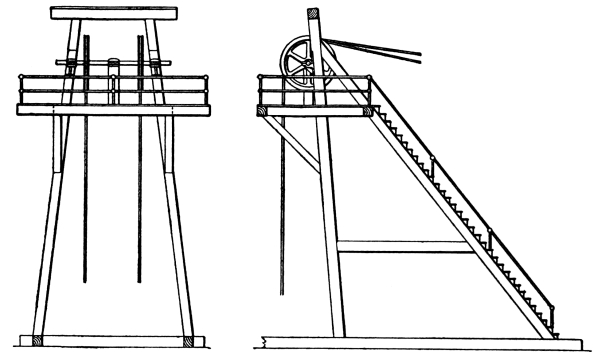
Fig. 33
Fig. 33 shows the construction of the ordinary timber gallows frame used at many ore mines.
Fig. 34 shows a steel A frame, of which the principal dimensions are as follows: height to sheave center 48 feet; base 33 feet 10 inches by 56 feet. Legs a and b are made of laced channels, as are also the central upright posts and cross-braces. The forward inclined legs are made of I beams. The weight of the frame is 98,000 pounds without the sheaves. The advantages claimed for this type of design are that it gives a very strongly braced frame while using a minimum of material. Also, in cases of overwinding, the cage goes over the top of the frame without injury to the frame, and should men be overwound they would fall only the height of the frame instead of being crushed against the top.
35. Square Type Without Inclined Brace.—Fig. 35 shows a steel frame in which the tendency to be overturned by the pull of the rope is resisted by a nearly vertical tension leg as explained in Art. 32. Each leg of the frame is built of channel bars connected by lattice bracing, as shown, and the legs are stiffened by horizontal channel cross-bars similarly braced and also by diagonal tie-rods, provided with turnbuckles.
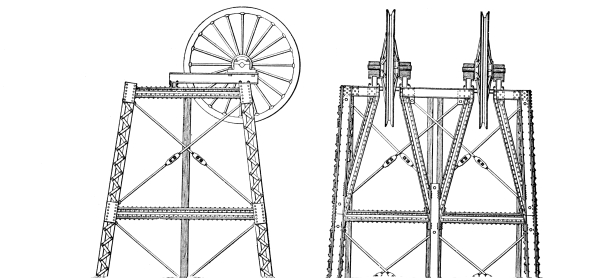
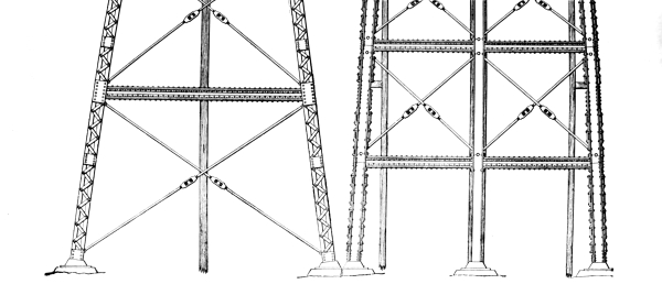
Fig. 35
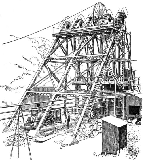
Fig. 34
Springs are sometimes placed under the journals of the head-sheaves to lessen the strain on the rope while starting the load; the 15-foot head-sheaves of the Robinson deep mine at Johannesburg have locomotive springs under the journal boxes, the actual load on each spring due to the weight of the sheave, rope, skip, and rock being equal to about 20,000 pounds; it was estimated that the sheave would thus be lowered by the load on it, about 3 inches, which would be equal to an action of a spring giving motion of 6 inches at the cage. Springs can often be used both on the rope and under the sheave in the same plant to advantage.
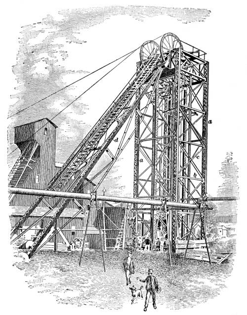
Fig. 36
36. Square Type With Inclined Brace.—Fig. 36 shows a very substantial frame with square tower and inclined brace.
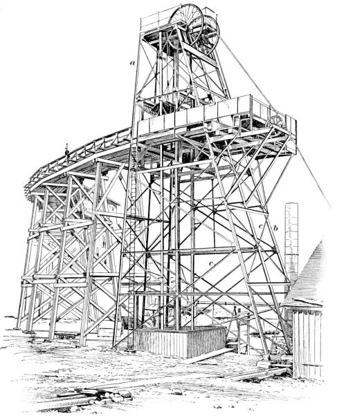
Fig. 37
Its principal dimensions are as follows: height to sheave center 59 feet 6 inches; base of tower 15 feet 8 inches by 14 feet; distance of bottom of inclined leg from vertical post 48 feet. Each end post a is composed of two channels, double-latticed. The horizontal members b are I beams and each inclined member c is made up of two angles. The inclined leg d is trussed as shown and built of channel and angle beams, the main member being made of two channels, the incline and base members of the truss being made up of two angles, and the short vertical member of two channels. The center post of the tower is similar to the end posts, except that the uprights are I beams instead of channels. The frame is designed for a static weight of 16,000 pounds and for a maximum strain on the cable of 32,000 pounds.
Fig. 37 shows a frame of similar form, but in which the landing platform is placed at a height above the surface, so that the cars hoisted can be run off on a trestle and thus be delivered at the top of a car, breaker, tipple, or ore house. Its principal dimensions are as follows: height to sheave center 75 feet; base 40 feet 11¾ inches by 21 feet 8½ inches. The leg a is made of two angles. The bracing leg b is built of two angles. The diagonal braces c are single angles. The horizontal braces are angles or channels of various sizes depending on the stresses.
37. The head-sheave is supported directly on top of the main frame, as shown in Figs. 32, 34, 36, and 37, or a small superstructure a is built on top of the main frame, as shown in Fig. 38, so that the base of the sheave journals is perpendicular to the resultant pull on the frame, that is, to the theoretical direction of the inclined leg of the frame if one is used.
38. Timber frames are usually built by the mining company from its own designs. Steel frames are generally built by the structural steel companies from detailed plans and designs furnished by the mining company, or from a skeleton diagram furnished by the mining company, giving the loads on the rope and the general conditions about the shaft to which the frame must conform, the frame being then designed and erected in detail by the steel company.
39. Enclosing Head-Frames.—Head-frames are sometimes wholly or partially enclosed to protect them and the men from the weather. A covering of boards is warmest. All woodwork should be painted with fireproof paint and ample means for extinguishing fire should be provided. A covering of corrugated sheet iron well painted on both sides to prevent rusting is often used instead of wood and lessens the danger of fire, but is not as warm a covering as wood.
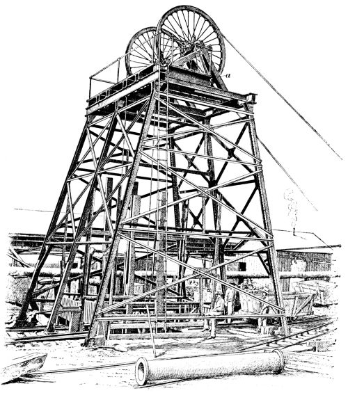
Fig. 38
40. In many states, it is required by law that the top of the shaft be protected by a fence or by gates to prevent persons falling down the shaft. This protection is secured at the sides of head-frames by extra timbers or beams forming part of the frame, or by means of a fence placed near the sides of the frame. The ends of the shaft are protected by a bar placed across uprights, by gates that swing like an ordinary door, or more generally by vertical sliding gates that are raised by the cage when it comes to the surface and drop into place when the cage descends. Similar gates, doors, or bars should be used at all landings below the surface.
HEAD-FRAME SPECIFICATIONS
41. The following is a sample set of specifications for a steel head-frame to be built from detailed plans furnished by the mining company.
This head-frame to be made from drawings to be furnished by the—— Coal Company, and placed on foundations furnished by said company.
Material.—Structure to be built throughout of soft structural steel, net strength 55,000 to 62,000 pounds per square inch; elastic limit not less than 30,000 pounds per square inch; elongation, 25 per cent.; bending test, bend flat on itself without fracture.
Builder agrees to guarantee structure to withstand strains specified on drawings with factor of safety of 10, to provide for possible overwinding or sticking in shaft.
No steel shall be used less than ¼ inch thick except for lining or filling vacant places.
Workmanship.—The tower to be built in a neat and workman-like manner. The pitch of the rivets (distance between centers) shall not exceed 6 inches or sixteen times the thinnest plate, nor be less than three diameters of the rivets.
The rivets used shall generally be ½ inch, ¾ inch, and ⅞ inch in diameter.
The distance between edges of any piece and the center of rivet hole shall not be less than 1¼ inches, except for bars less than 2½ inches wide; when practicable it shall be at least two diameters of the rivet. All rivet holes shall be spaced and punched, so that when the several parts are assembled together a rivet of ¹/₁₆ inch less diameter than the hole can be entered hot into any hole, without reaming or drifting. The rivets when driven should fill the holes. The heads must be rounded; they must be full and neatly made, and be concentric to the rivet hole, and thoroughly pinch the connecting pieces together. Field riveting must be reduced to a minimum. All joints and connections shall be neatly made, the several parts to be brought together without twists, bends, or open joints.
Inspection.—All facilities for inspecting the material and workmanship shall be given by the builders during the erection of the head-frame. The company reserves the right to reject any or all parts not built in accordance with the plans or these specifications. Final inspection of work 1 month after being in actual service.
Painting.—All work, before leaving the shops, shall be thoroughly cleaned from all loose rust and scale, and be given one good coat of paint well worked into all joints and open spaces. In riveted ironwork, the surfaces coming in contact shall each be painted before being riveted together. Bottoms of bearing plates and any parts that are not accessible for painting after erection shall have two coats of paint. After the structure is erected in place, it shall be given one coat of paint. All recesses that will retain water, or through which water can enter, must be filled with thick paint or some waterproof cement before receiving the final painting. The paint shall be a lampblack paint, mixed with pure linseed oil, or of red lead mixed with raw linseed oil containing Japan dryer.
General Clauses.—The specifications and drawings are intended to cooperate and to indicate the principal dimensions and requirements necessary to the complete structure. It being understood that while some work may be shown in the plans and not described in the specifications, or vice versa, and some minor details and fastenings are omitted from both plans and specifications, the work is to be executed without extra charge therefor, the same as if the minutest details were set forth in full in both drawings and specifications. The contractor is to make good any defects of material or workmanship developing within 1 year after final acceptance.
The contractor shall furnish a location plan and also two copies of the detail shop drawings for convenience in making future alterations and repairs.
Erection.—The head-frame is to be erected complete, secured to foundations provided by the _______ Company.
Contractor shall furnish all foundation bolts and washers. Iron stairway with hand rails beside main back bracers and platform with wooden floor under sheaves, also iron stairs from platform under sheaves to back sheave pedestal for oiling. Wood furnished by the ______ Company.
Price includes all material for completion of work delivered, erected, and riveted in place and painted.
The ______ Company will furnish and place in position the sheaves, with the shafts and boxes belonging to the same, also the wooden guides.
Delivery.—The head-frame to be erected, complete, and secured to foundations in ______ weeks from date of order.
DETACHING HOOKS
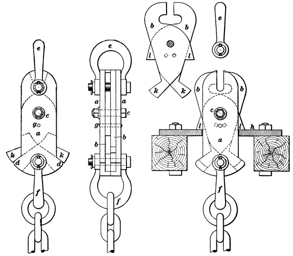
Fig. 39
42. In hoisting, there is more or less danger of overwinding or lifting the cage too far, and dashing it against the top of the head-frame, or if the top is open the cage may be pulled entirely over the top. Detaching hooks are intended to prevent this. Several varieties of such hooks are made, which differ from each other only in their smaller details. In all of them, detachment is effected by passing the rope through a circular hole in an iron plate or through an iron cylinder, the diameter of which is sufficient to allow the upper portion of the hooks to pass through when passing upwards, but the lower portion is made larger and so arranged that when this larger part strikes the plate the upper portion is forced open and the hoisting rope released. After the upper part has been thus opened, it is too large to pass back through the opening and the plate and the cage is therefore held suspended. Fig. 39 shows such a hook. It consists of two outside fixed plates slightly narrower at the top than the diameter of the hole in the disengaging plate h. Between the frame plates a are two inner plates b that move about a strong pin c passing through both plates a and b, but near the bottoms there are two projections d to prevent the hook from passing entirely through the hole. The winding rope is attached to the top shackle e and the cage to the lower shackle f. When the two movable plates b are closed as tightly as possible at the top about the pin of the shackle e, they are secured by a copper pin g. In case of overwinding, when the hook passes into the hole of the disengaging plate h, the two projections k on plates b are pressed inwards, shearing off the copper pin g and allowing the plates b to turn about the central bolt c, thus releasing the shackle e. The plates b are then in such a position that the projections l on them cannot pass down through the hole. The cage then hangs by the hooks from the disengaging plate, and the rope passes on. An objection raised against this hook is that, being constructed of plates, there is considerable surface in contact between the moving parts, and unless they are regularly taken apart and oiled, there is danger of their rusting firmly together.
In England, detaching hooks are used quite commonly, and also in certain parts of the Central Basin in the United States, but they have not yet been generally adopted throughout the United States.
43. It is claimed by many that such devices inspire the engineer with a misleading feeling of security; that they are more or less complicated in construction and so need care, and destroy the simplicity of the plant; that they may be the direct cause of accident by introducing new elements of danger; that they add to the cost; and that they are not thoroughly reliable. Again, it is held that the surest prevention of overwinding is obtained by the employment of a sober, reliable, and competent engineer, who is held personally responsible for overwinding accidents; by having a good brake and an engine thoroughly under the control of the engineer; by a reliable method of indicating the position of the cage; by sufficient height to head-sheaves to allow of considerable hoisting over and above that necessary for landing.
SIGNALING
44. Some method must be provided for communicating between the bottom or any level of a shaft and the top landing or the engine room, also between the top landing and the engine room, so that the hoisting engineer may be notified when both the head-man and foot-man are ready for him to hoist. A common method of signaling is by means of a gong, bell, or triangle placed in the engine room and connected by a wire or small wire-rope with the point from which it is desired to signal. Attempts have been made in different localities and by different associations to adopt a standard code of hoisting signals, and while it would be advantageous if this could be done, none of the attempts made have been entirely successful. Although there is no uniform system of signals, one bell generally means stop, two bells lower, three bells hoist, and four bells hoist men.
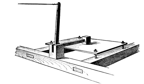
Fig. 40
45. Hammer-and-Plate Signal.—Fig. 40 shows a hammer-and-plate signal, the plate being a piece of boiler iron or steel. The hammer is often located beneath the plate instead of above, as shown. Another style of hammer-and-plate is shown in Fig. 41. The hammer is made of 2-inch square iron and heavy enough to balance the weight of wire hanging in the shaft and to take the sag out of the horizontal wire connecting the top of the shaft with the lever a. A simple dial turned by a ratchet motion attached to the lever a is sometimes used to show the number of strokes, and thus check the number counted by the engineer. The dial is reset by the engineer as soon as he understands the signal.
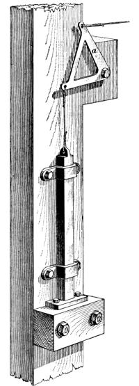
Fig. 41
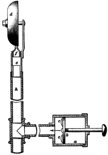
Fig. 42
46. Electric Bells.—Electric bells operated by push buttons are rapidly coming into use for mine signaling on account of the ease and completeness with which such a system can be installed. Electric flash lights are also extensively used for signaling purposes. The principle of action and details of the wiring for electric signals and flash lights have been described in Transmission, Signaling, and Lighting.
47. Speaking Tubes.—The laws of certain states require speaking tubes, in addition to the ordinary means of signaling. These speaking tubes are generally made of 2-inch iron pipe and are from 300 to 1,500 feet long, and are often provided with whistles at the end of the pipe and at each level of the mine, by which the attention of persons at any level can be attracted or the whistle may be omitted and the attention of persons attracted merely by rapping on the pipe with a piece of iron.
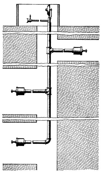
Fig. 43
48. Pneumatic Gong Signal.—Fig. 42 shows an attachment that can be connected to a speaking tube and that is widely used for signaling. It consists of a brass cylinder a fitted with a piston b containing valves c. The gong d is attached to the cylinder e inside of which the clapper f fits loosely. When the piston is pushed inwards, as shown by the arrow, by means of the handle, the air in the cylinder and in the pipe h is compressed and forces the clapper f upwards against the gong d. The arrangement of these gongs in the mine is shown in Fig.43. A cylinder and whistle are usually placed at each landing and a gong and whistle in the engine room, though, if desired, a cylinder, whistle, and gong may be placed at each landing and in the engine room.
49. Telephones.—Telephones connecting the different levels with the top and the engine room are now frequently used in connection with other signal systems, but they are not as well adapted as bells or gongs for rapid-hoisting signaling.