Chapter LVIII · CURRENT AND PRESSURE LIMITING DEVICES
Reading edition
In any electric installation there must be provided a number of automatic devices to secure proper control. The great multiplicity of devices designed for this purpose may be divided into two general classes, as
1. Current limiting;
2. Pressure limiting.
Because of the heating effect of the current which increases in proportion to the square of the strength of the current, it is necessary to protect circuits with devices which do not allow the current to exceed a predetermined value.
Accordingly fuses, circuit breakers, reactances, etc., are used, each possessing certain characteristics, which render it suitable for particular conditions of service.
For instance, just as in analogy, steam boilers must be protected against abnormal pressures by safety valves, electric circuits must be guarded against excessive voltages by pressure limiting devices, otherwise much damage would occur, such as the burning out of incandescent lamps, grounding of cables, etc.
The control of steam is simple as compared to the electric current, the latter being the more difficult to manage because of its peculiar behaviour in certain respects, especially in the case of alternating current which necessitates numerous devices of more or less delicate construction for safety both to the apparatus and the operator.
Fuses.—A fuse is "an electrical safety valve", or more specifically, the actual wire or strip of metal in a cut out, which may be fused by an excessive current, that is to say, by a current which exceeds a predetermined value. A fuse, thus serves to protect a circuit from any harm resulting from an undue overload.
Fuses have been treated at such length in Guide No. 2, Chapter XXV, that very little can be said here, without repetition.
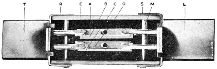
Fig. 2,238.—Sectional view of Noark 250 volt, 400 ampere enclosed fuse. The fusible element is divided into strips A, B, C, and D. This parallel link construction results, upon the operation of the fuse, in the formation of a number of small arcs, thus facilitating the absorption of the metal vapor formed when the fuse blows. The fusible strips, of which there are two or four in number, according to the ampere capacity of the fuse, are entirely surrounded by a granular material which is chemically inactive with respect to the fusible link and whose function is to absorb the metallic vapor formed upon the blowing of the fuse. The contact blades T and L are made of round edge copper, the round edges facilitating the insertion of the fuses in the circuit terminals. R and S are the end ferrules, attached to cover E, by the pin M.
Ques. What effect have the terminals on a fuse?
Ans. The current at which a fuse melts may be greatly changed by the size and shape of the terminals.
If near together and large, they may conduct considerable heat from the fuse thus increasing the current required to blow the fuse.
Ques. What is the objection to large fuses?
Ans. The discharge of molten metal when the fuse blows is a source of danger.
Ques. What should be used in place of large fuses?
Ans. Circuit breakers.
Ques. What are the objections to fuses in general?
Ans. The uncertainty as to the current required to blow them; the constant expansion and contraction is liable to loosen the terminal screws when screws are used.
Ques. What is the advantage of fuses?
Ans. They form an inexpensive means of protecting small circuits.
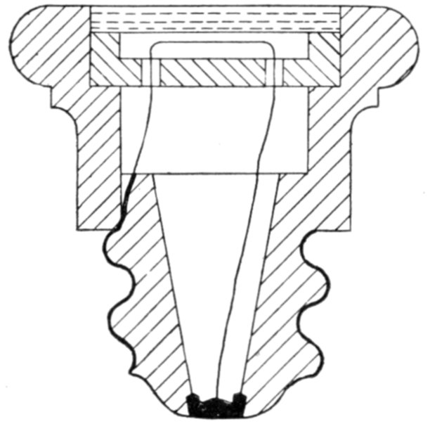
Fig. 2,239.—Cross section through plug fuse. With this type of fuse it is impossible to place any except the correct size of plug in the socket.
Ques. Describe a plug fuse.
Ans. It is constructed as shown in fig. 2,239, the fuse wire being visible and stretching between the two metal portions of the plug.
Ques. What is a cut out fuse?
Ans. One similar to a simple fuse, but provided with clip contacts as used for knife switch contacts.
The fuse wire is usually contained in a china or porcelain tube, which also serves the purpose of a handle for withdrawing the fuse.
Ques. What is an expulsion fuse?
Ans. One in which the fuse is placed in an enclosed chamber with a vent hole.
In operation, when the fuse blows, the hot air and molten metal are expelled through the vent.
Ques. What is a no arc fuse?
Ans. A cartridge type fuse, in which the space surrounding the fuse wire is filled with powdered material.
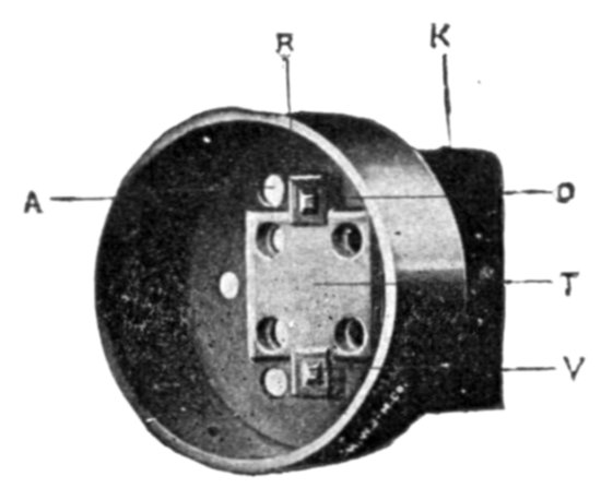
Fig. 2,240.—Inside view of end ferrule of Noark enclosed fuse. Two prongs O and V, which are a part of the knife blade K, pass through the square holes in the ends of the ferrule R, and are riveted to the anchor plate T. The object of this plate is to stiffen the structure and to increase the current carrying capacity of the metal between the holes, also to permit of proper alignment of the plates. In each ferrule is placed a vent screen, composed of reticulate material, such as cheese cloth. The fuzz between the threads of the cheese cloth prevents the escape of the granular material through the vent holes A, but when the fuse operates, allows free egress of the air, thereby permitting the vapor formed upon the operation of the fusible element to quickly and freely pass through the interstices of the filling material and become cooled, eliminating any possibility of flame issuing from the ends of the tube.
The object of the powdered material is to assist in extinguishing the arc formed when the fuse blows.
Ques. What is a magnetic blow out fuse?
Ans. An enclosed fuse which is subject to the action of a magnetic field produced by the current, the magnetic field tending to blow out the arc when fusing occurs.
Ques. What is a quick break fuse?
Ans. One having a weight suspended from its center, or springs attached to its ends so that the arc formed at fusing is quickly attenuated and extinguished.
Ques. What is the disadvantage of a fuse as compared to an oil switch circuit breaker?
Ans. When a fuse blows, the arc causes oscillations in the line, which cause excessive rise of pressure under certain capacity conditions, whereas this disturbance is reduced to a minimum with an oil switch.
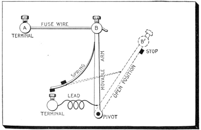
Fig. 2,241.—Quick break fuse. The fuse wire is connected between the fixed terminal A and the movable arm B, and is held under tension by the spring which exerts pressure on the movable arm in a direction tending to separate A and B. In operation, when the fuse blows, the movable arm quickly moves to the position B´, thus attenuating the arc and accelerating its extinguishment.
Ques. What metal is used for fuse wires?
Ans. Various metals. Ordinary fuse wire is made of lead or an alloy of lead and tin.
Ques. What is the objection to aluminum?
Ans. It becomes coated with oxide or sulphide, which acts as a tube tending to retain the metal inside and prevent rupture.
Ques. What is the objection to copper?
Ans. Its high fusing point.
Current Limiting Inductances.—The great increase in capacity of power stations, for supplying the demands of densely populated centers and large manufacturing districts, together with the decrease in the reactance of modern alternators and transformers due to improvement in design to obtain better regulation, has presented a problem in apparatus protection not contemplated in the earlier days of alternating current distribution. This problem is entirely separate and distinct from that of eliminating the tendency toward short circuit, incident to the high voltages now common in transmission lines. It accepts that all short circuits must occasionally occur and considers only the protection of the connected apparatus against the mechanical forces due to the magnetic stresses of such enormous currents.

Fig. 2,242.—Notched end fuse. This is a simple form of fuse consisting of a strip of metal (or wire) fixed between two end pieces to fit around the terminals. This type is often proportioned so that it is only possible to place the correct size of fuse in the terminals. Sometimes, in place of the end pieces as shown, the fuse metal is fixed between two clamping screws.
Ques. What means are employed to limit the value of a short circuit current?
Ans. A current limiting inductance coil (called a reactance) is placed in series with the alternators or transformers.
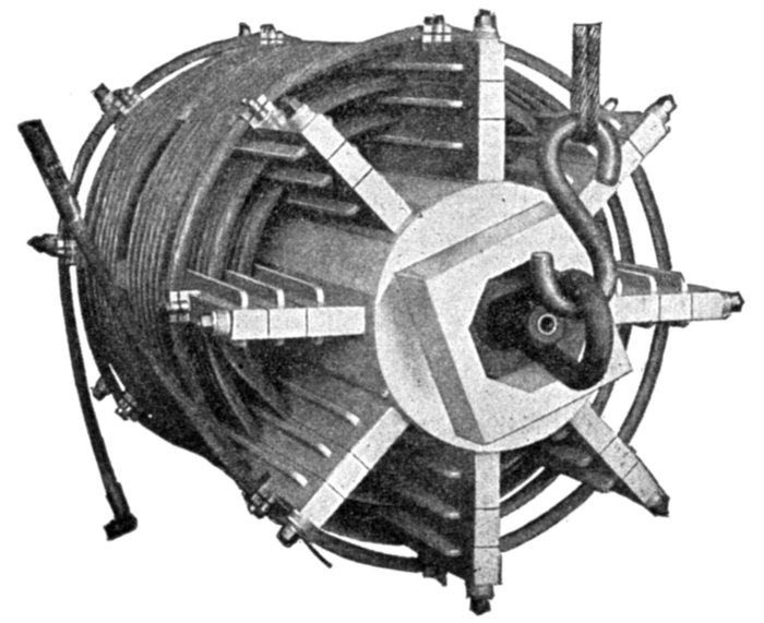
Fig. 2,243.—General Electric current limiting reactance; view showing details of construction. The core consists of a hollow concrete cylinder, alloy anchor plates or sockets being embedded in the core near the ends to receive the radial brass bolts. An extension at each end of the core provides for clamping and bracing the reactance in installation. The supports for the winding are made of resin treated maple and are located upon the core by radial brass studs screwed into the alloy sockets, and insulated by mica tubes. The nuts by which the structure is tightened, rest upon heavy fibre washers. Wooden barriers fitted and shellacked into the supports add to the creepage surface between layers of the winding and between the winding and the core. The supports of the layer next to the core are separated from the core by strips of treated pressboard. The coil consists of bare stranded cable in several layers, usually three in number. It is wound into grooves in the treated wood supports, which are protected from contact with the cable by heat shields of asbestos shellacked into the grooves. The winding is usually in the form of two back turn sections, thereby allowing the terminals of the coil to be brought out at the ends of the outside layer. This assures accessibility and ease of connection, and the removal of the leads from proximity to the core. Two turns at each end of the winding are given extra spacing for the purpose of additional insulation. The final turn at each end of the coil is securely held in place by alloy clamps bolted to the supports. The wood is protected from contact with the clamps by shields of asbestos. The ends of the cable between the two sections are welded by the oxyacetylene process.
Ques. What are its essential features of construction?
Ans. It consists of bare stranded cable wound around a concrete core and held in place by wooden supports as shown in fig. 2,243.
In order to avoid the prohibitive expense of high voltage insulation, the reactance coil is designed for the low tension circuit. This requirement prohibits the use of a magnetic core which, if economically designed for normal operation, would become saturated at higher densities, or, if designed large enough to avoid saturation at short circuit conditions, would become prohibitive in cost and dimensions.
The elimination of all magnetic material from the construction of the concrete core reactance permits of no saturation, and assures a straight line voltage characteristic at all current loads.
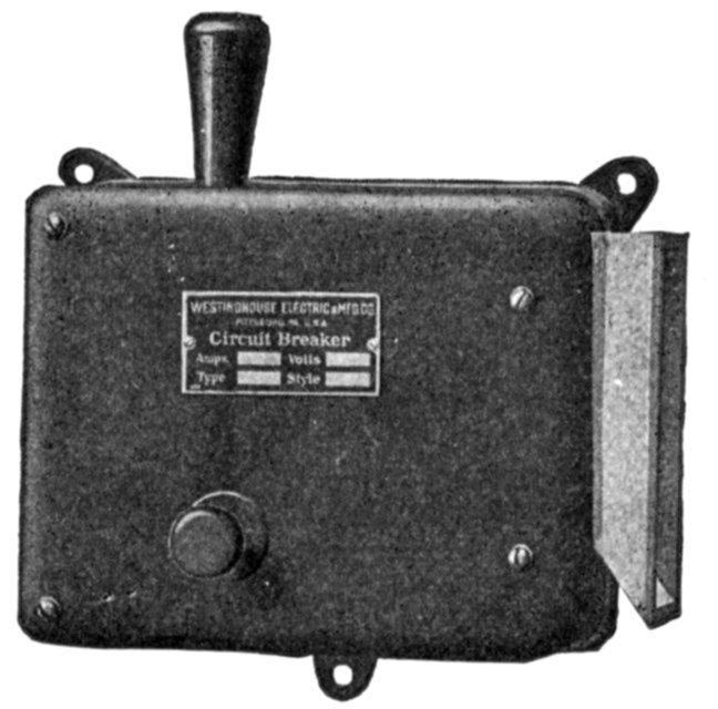
Fig. 2,244.—Westinghouse magnetic blow out circuit breaker, designed for the protection of street railway and electric locomotive equipments; it serves the combined purpose of fuse block and canopy switch. The contact tips are surrounded by a moulded arc chute which confines and directs the arc until the magnetic blow out extinguishes it. The current carrying contacts consist of copper strips separated by air spaces. An auxiliary contact or "arcing tip" at the end of the switch lever takes the burning of the arc when the breaker opens, and thus confines the burning to a very small piece which can be easily removed and replaced at small cost. The hand tripping lever and the resetting lever have insulated handles, so that they can be safely handled, even in the dark.
Ques. Where is the proper location for a current limiting reactance?
Ans. As near the alternator as possible.
Ques. Why?
Ans. To lessen the possibility of a short circuit occurring between the reactance and the alternator.
Ques. Beside limiting the current, what other service is performed by the reactance?
Ans. It protects the alternator from high frequency surges coming in from the outside, and limits the current from other machines on the same bus.
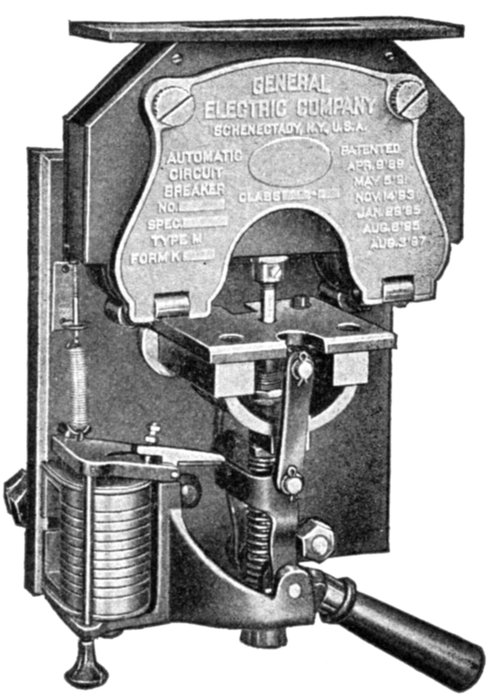
Fig. 2,245.—General Electric magnetic blow out circuit breaker. This type may be used in air or water tight boxes and is peculiarly adapted for service where the arc must be confined.
Circuit Breakers.—The importance of circuit protective devices, commonly called circuit breakers, is fully recognized. The duty of a circuit breaker is to protect the apparatus in an electrical circuit from undesirable effects arising from abnormal conditions, by automatically breaking the circuit. Accordingly a circuit breaker must comprise a switch in combination with electrical control devices designed to act under abnormal conditions in the circuit.
A circuit breaker is a device which automatically opens the circuit in event of abnormal conditions, in the circuit.
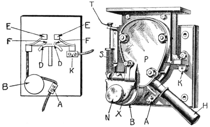
Fig. 2,246.—Magnetic blow out circuit breaker. This is a direct current breaker in which the final break occurs in a magnetic field. It is a principle in electromagnetics that a conductor carrying a current in a magnetic field will tend to move in a direction at right angles to the field. The arc set up on breaking a circuit constitutes a conductor, and in magnetic blow out circuit breakers, as generally manufactured, there is an electromagnet, energized by the current to be broken, which produces a field in the neighborhood of the arc, with the result that the arc moves outward, and so becomes attenuated and is finally extinguished. The form shown in the figure is used on cars equipped with heavy motors. When so used, it is in many cases mounted in a box with the handle H projecting at one end. A and K are the terminals of the breaker and B is the tripping coil, which also serves to set up the magnetic field necessary for blowing out the arc. X is the armature of coil B and is pulled down against the action of the spring S whenever the current exceeds that for which the breaker is set. The tripping current is adjusted by means of nut T. The iron plate P and a similar one back of it are magnetized by the current in coil B, and as the break takes place between these two poles, the arc is promptly extinguished by the field that exists there. In operation, A and K are the terminals, D D is a contact that is forced up against F, F when the breaker is set. The current then takes the path A-B-F-D D-F-K. When the breaker trips, the contact piece D D flies down and the tendency is for an arc to form between F, F; the magnetic field blows the arc upwards, and whatever burning takes place is on the contacts E, E, which are so constructed that they may be readily renewed. To trip the breaker by hand, the knob N is pressed.
In the design of circuit breakers, there are several methods used to effect the rupturing of the arc between contacts when opened on heavy overload, such as:
1. Magnetic blow out; 2. Thermal break; 3. Carbon break.
In the magnetic blow out type, the arc is extinguished between auxiliary contacts confined by a chute in which the arc is rapidly blown out due to a powerful magnetic field from one or more electromagnets. This type may be used in air or watertight boxes and is peculiarly adapted for service where the arc must be confined.
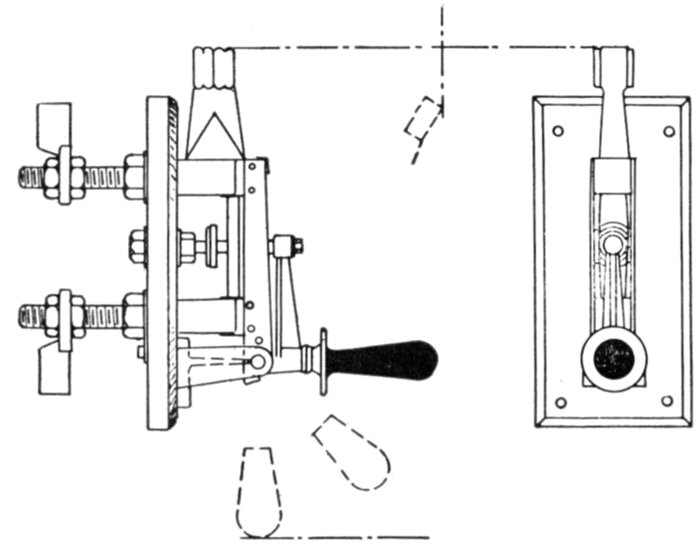
Fig. 2,247.—Thermal overload circuit breaker. In construction two contact blocks are fixed rigidly to, but insulated from, the switch arm. They are connected electrically by two parallel strips of suitable metal, each fitted with a steel catch piece. When the switch is closed the strips are sprung apart over a fixed catch, and the full rated current does not release the catch. Overload causes the strips to move apart, and the circuit breaker flies off under the action of a spring.
In a carbon break type, the arc is finally ruptured between carbon break contacts. The breaking of the circuit is accomplished progressively, that is to say, it is done in three stages, by several sets of contact, known respectively as
1. The main contacts;
2. The intermediate contacts;
3. The carbon contacts.
In operation, as the circuit breaker acts to break the circuit, first the main contacts, separate, then the intermediate contacts, and finally the carbon contacts between which the arc is ruptured.
Ques. What is the object of the intermediate contacts?
Ans. To prevent the forming of an arc on the main contacts.
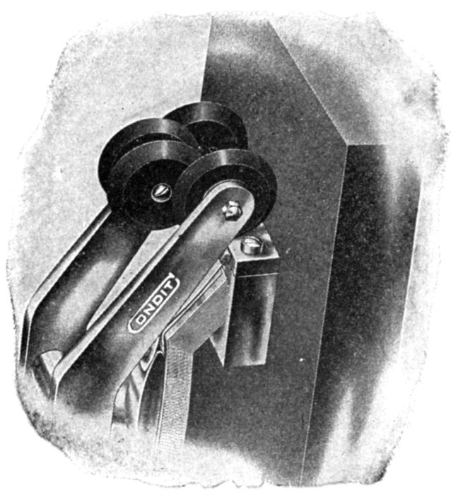
Fig. 2,248.—Carbon break discs of Condit circuit breaker. The two pairs of similar discs which slide past each other are so arranged that these surfaces coincide at the instant the intermediate contacts separate after which, as the contact arm opens further, they gradually disengage.
Ques. What is the object of the carbon contacts?
Ans. First to protect the intermediate contacts by providing a path for the current after the intermediate contacts separate, and 2, to "slow down" the current by means of the considerable resistance of the carbon, thus reducing to a minimum the arc which is formed when the carbon contacts separate.
Ques. How is the automatic operation of a circuit breaker usually accomplished?
Ans. Usually through the medium of a solenoid, or electromagnet energized by current from the circuit controlled by the breaker.
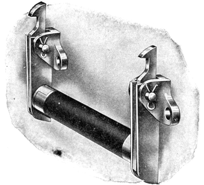
Fig. 2,249.—Mechanically connected insulated latches used on Condit circuit breakers to produce inter-locking tripping.
The essential features of construction and operation of a circuit breaker is shown in the elementary diagrams, figs. 2,250 to 2,253. In construction as shown in fig. 2,250 it consists essentially of three sets of contacts, a swinging contact arm which is set in the closed position by the handle operating through the toggle joint, the movement of which is limited in the closing direction by the stop. The latter is made adjustable by an eccentric pin or equivalent. Connected to the toggle is the plunger of the solenoid whose winding is energized by current from the circuit which the circuit breaker is to control.
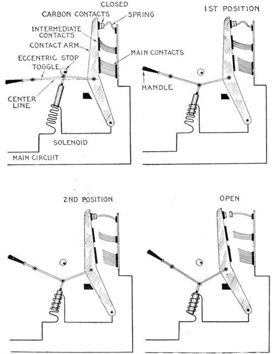
Figs. 2,250 to 2,253.—Elementary diagrams illustrating the operation of a carbon circuit breaker of the overload type, showing the progressive opening of such device. Fig. 2,250, closed position; fig. 2,251, main contacts open; fig. 2,252, intermediate contacts open; fig. 2,253, carbon contacts open, circuit broken.
In operation, the circuit is closed by hand by turning the handle downward to the position shown in fig. 2,250, that is as far as it will go.
Since the toggle has passed the center line the arm will be held normally in this position because of the spring action of the contacts. Now, if the current rise above a predetermined limit, the pull exerted by the solenoid will overbalance the tendency of the toggle to remain in the closed position, and pull the two toggle links downward below the center line, drawing the contact arm back and breaking the circuit.
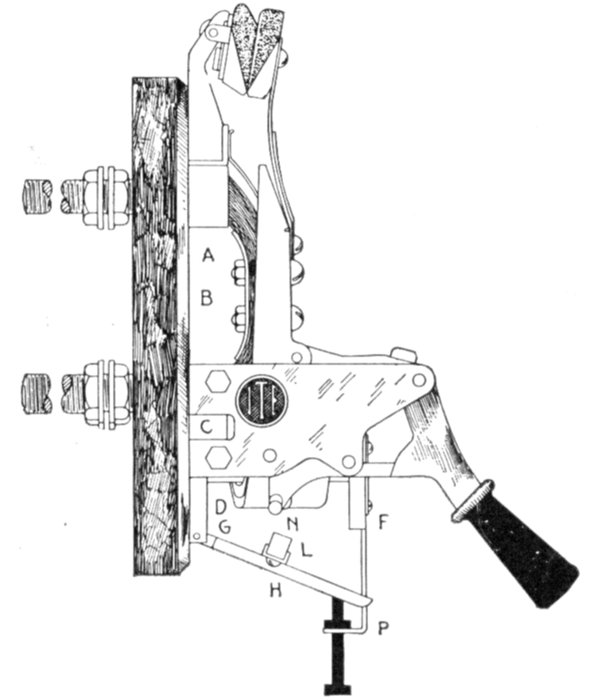
Fig. 2,254.—I-T-E overload circuit breaker. In operation: the current from one side of the circuit enters the circuit breaker at A, passing through the laminated bridge B to contact block C, thence through coil D and terminal E to the motor. The coil D surrounds a magnetic core, having pole pieces F and G and armature H. The effect of the current in the coil is to energize the magnet, thus tending to lift the armature against the force of gravitation. The volume of current required to trip the circuit breaker is determined by the position of the armature, which is subject to ready adjustment, and is indicated on the calibration plate P. From the opposite side of the line, the current enters at I, passing downward through the laminated bridge member J, into terminal K, whence it passes out to the motor. When the current passing through the circuit breaker attains sufficient volume, the force generated by the magnetic coil overcomes the weight of the armature H; and the latter is drawn upward toward the pole pieces with constantly increasing force, until the insulated projections L and M strike against the respective restraining latches N and O, thereby releasing the two switch members, which at once open in response to the force supplied by the spring of the contact members and auxiliary springs provided for the purpose. Positiveness in opening is further assured by the blow of the armature, which is added to the other opening forces; hence, the heavier the overload, the more violent the blow and the quicker the circuit breaker opens; or the greater the current the more promptly it is interrupted. This is the I-T-E or Inverse Time Element principle.
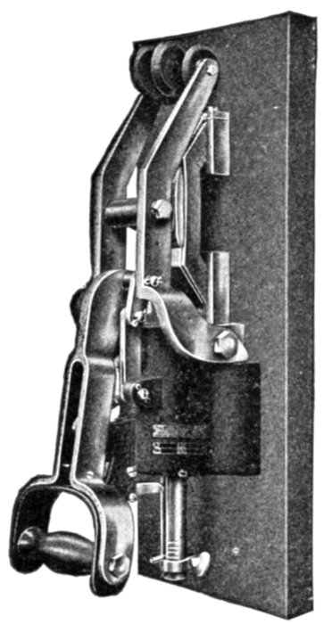
Fig. 2,255.—Condit 600 volt, 1,200 ampere, single pole, type K, circuit breaker with pull down handle.
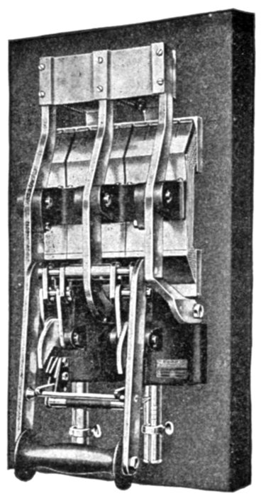
Fig. 2,256.—Condit 600 volt, 6,000 ampere, single pole, switch board mounting, circuit breaker, with pull down handle.
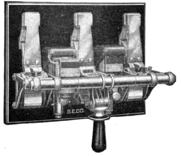
Fig. 2,257.—General Electric triple pole, overload, circuit breaker, with two overload coils, capacity 300 amperes, 480 volts.
The progressive action which takes place during this operation is shown in figs. 2,250 to 2,253 in which the main contacts separate first, then the intermediate, and finally the carbon contacts as mentioned before.
Ques. What name is given to this type of circuit breaker?
Ans. It is called an overload circuit breaker.
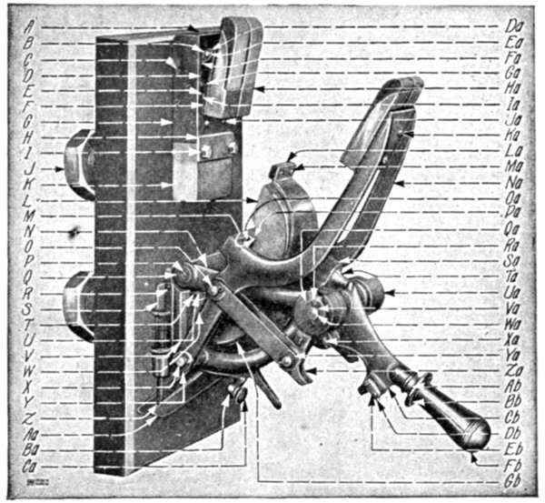
Fig. 2,258.—Parts of General Electric 2,000 ampere 650 volt circuit breaker. A, cover for secondary contact bracket; B, spring washer for Ea.; C, pin for links and G; D, spring for carbon support; E, plate for F; F, carbon support; G, secondary contact bracket; H, contact plate; I, screw for H; J, nut for K and W; K, contact stud, upper; L, laminated brush, complete with support; M, leather buffer for L; N, main link; O, pin for Na and La left hand and Cb and Na right and left hand; P, screw for N and magnet frame shaft; Q, washer for N and magnet frame shaft; R, screw for S and V; S, index plate; T, plate for Gb; U, screw for T; V, magnet frame; W, contact stud, lower; X, pin for Cb, Na and V; Y, washer for X and O; Z, calibrating screw with thumb nut; Aa, armature with contact plate; Ba, catch lever complete with catch Ca, button handle for Ba; Da, spring cotter for Ea; Ea, pin for F and Fa; Fa, operating link for G; Ga, pin for D; Ha, carbon holder with copper and carbon contacts; Ia, flexible connections for G and F; Ja, screw for G and flexible connection plate; Ka, screw for Na and Ha; La, copper secondary contact; Ma, screw for La; Na, secondary contact lever; Oa, cross bar for Na; Pa, screw for L and M; Qa, secondary toggle link (left hand); Ra, spring cotter for Wa and O; Sa, brush lever; Ta, buffer for Cb and Sa; Ua, secondary toggle link (right hand); Va, washer for Wa; Wa, pin for Cb, Qa, Ua and N; Xa, pin for Sa and Cv; Ya, spring cotter for all pins, except Wa, catch lever pin and buffer; Za, secondary contact link; Ab, washer for Fb; Bb, guard for Fb; Cb, handle lever; Db, catch for Cb; Eb, screw for Db; Fb, handle with stud; Gb, secondary connection.
Automatic Features.—There are three methods of connecting the winding of the solenoid, or trip coil as it is called:
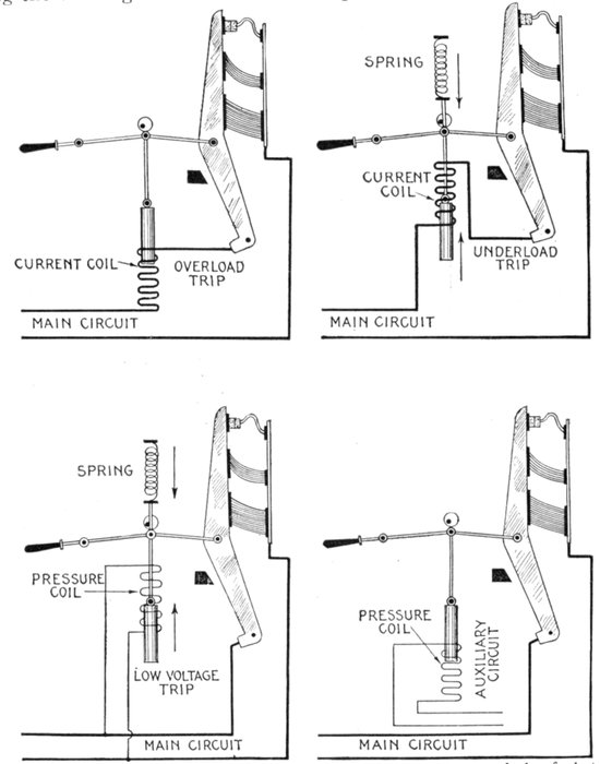
Figs. 2,259 to 2,262.—Elementary diagrams illustrating the various methods of electromagnetic control for circuit breakers. Fig. 2,259, overload trip; fig. 2,260, underload trip, fig. 2,261, low voltage trip; fig. 2,262, control from auxiliary circuit by means of a "relay."
1. In series with the main circuit;
2. In shunt with the main circuit;
3. In shunt with an auxiliary circuit.
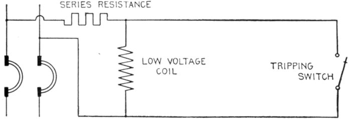
Fig. 2,263.—Diagram of General Electric low voltage trip with tripping switch normally open.
The automatic controls arising from these connections give various kinds of protection to the circuit and are known as
1. Overload trip;
2. Underload trip;
3. Low voltage trip;
4. Auxiliary circuit trip.
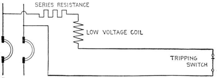
Fig. 2,264.—Diagram of General Electric low voltage trip, with tripping switch normally closed.
Ques. What is the object of the overload trip?
Ans. It is intended to open the circuit when the current exceeds a predetermined value.
Ques. What modifications are made in the mechanism shown in the elementary diagrams?
Ans. Sometimes a latch is used in place of the toggle and a magnet in place of the solenoid as in figs. 2,265 and 2,266.
Ques. Why is a magnet used in combination with a latch?
Ans. Because with this arrangement very little movement is required to trip the breaker, and for such conditions, a magnet is more efficient than a solenoid.
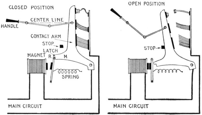
Figs. 2,265 and 2,266.—Circuit breaker with automatic control mechanism consisting of magnet and latch; views showing breaker in open and closed positions, and essential features. The toggle is used to obtain sufficient leverage to easily close switch against the pressure of the brush contacts but not to lock switch, this being done by the latch as shown, the latter closing by the action of a spring, there being a roller R at the end which engages the arm to reduce friction. In operation, when the current exceeds a predetermined limit the magnet attracts the latch and releases the contact arm. The brush contacts which are exerting pressure against the contact arm, rapidly push it away, and assisted by gravity, the arm flies open to the position shown in fig. 2,266.
Ques. How does the latch arrangement work?
Ans. When the proper current is reached, the magnet pulls open the latch and the contact arm of the breaker moves by the force of gravity or other means and opens the circuit.
Ques. How does the underload trip operate?
Ans. The same as the overload type except that they operate on a diminution of current instead of an excess.
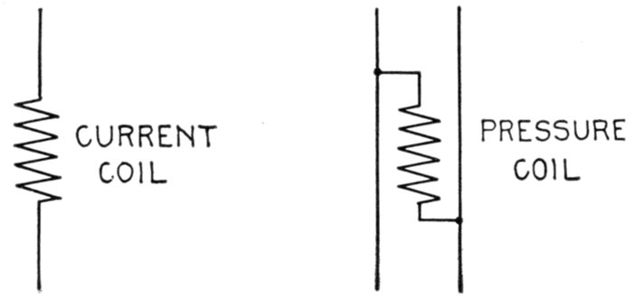
Figs. 2,267 and 2,268.—Positions in circuit of current and pressure coils of circuit breakers.
Ques. Describe the no voltage trip.
Ans. The energy for the trip of this breaker is derived from a high resistance or fine wire coil which is arranged to be placed directly across the line, in operation, when the current flowing through the circuit falls below a predetermined value, the energy of the coil is insufficient to counteract the force of a spring, which then trips the breaker.
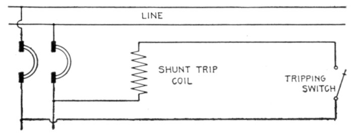
Fig. 2,269.—Diagram of General Electric shunt trip with coil connected beyond breaker and thrown out of circuit after tripping.
Ques. Describe the auxiliary circuit trip.
Ans. A pressure coil is used which is energized by current from an auxiliary circuit. The coil is only momentarily energized, by push button, relay or other control, as distinguished from the preceding types, in which the coil is constantly energized.
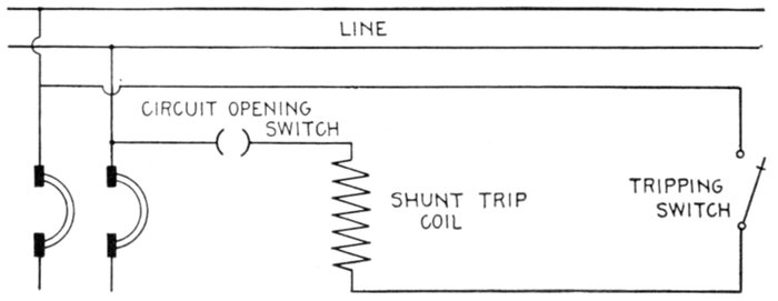
Fig. 2,270.—Diagram of General Electric shunt trip with auxiliary circuit opening switch to throw coil out of circuit after tripping.
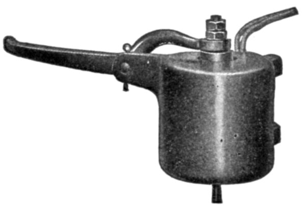
Fig. 2,271.—General Electric shunt trip attachment. The shunt trip attachment has been designed to provide for conditions under which the low voltage attachment cannot be successfully applied. It resembles the low voltage attachment in construction, but differs in that it trips the circuit breaker when energized. The shunt trip should be allowed to remain only momentarily in circuit; hence it should be so connected that the opening of the circuit breaker immediately disconnects it from the circuit. Whenever it is impossible to connect the shunt trip in this manner, the circuit opening auxiliary switch should be used in connection with it.
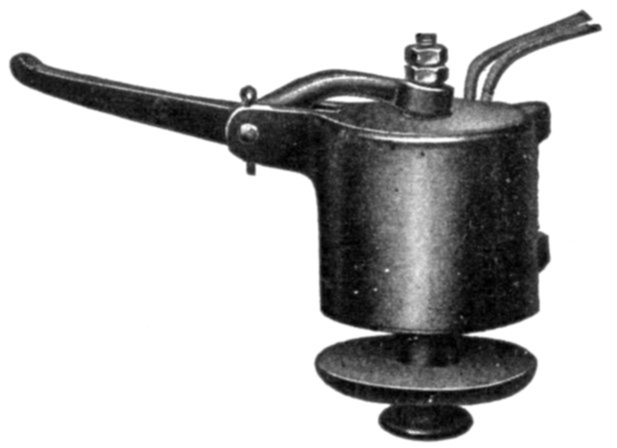
Fig. 2,272.—General Electric low voltage attachment for circuit breakers. This low voltage trip is designed to operate the circuit breaker when the line voltage drops to approximately 50 per cent or less of the normal voltage. It should be noted that the coil is always in circuit, as is the case with the overload and underload coils, and that it operates with the releasing of its armature. It is always necessary to use a fixed amount of resistance (depending upon the voltage of the system) in series with the low voltage release. The low voltage release performs the functions of a shunt trip coil when used in conjunction with a push button, auxiliary switch or speed limiting device, and is generally preferred to the shunt trip attachment.
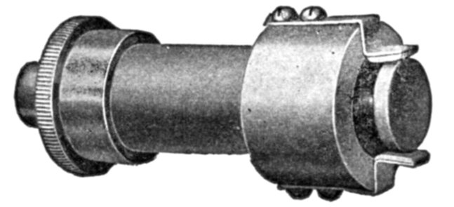
Fig. 2,273.—General Electric circuit opening auxiliary switch. This switch opens an auxiliary circuit when the circuit breaker opens, and is intended to be used in connection with a shunt trip attachment to insure the immediate disconnection of the shunt coil from the circuit. It may also be employed to serve other purposes, such as tripping another circuit breaker having a low voltage attachment, and permitting another circuit breaker to remain closed only when the circuit breaker equipped with the auxiliary switch is open.
Ques. What other name is given to the auxiliary circuit trip?
Ans. It is sometimes called the shunt trip, though ill advisedly so.
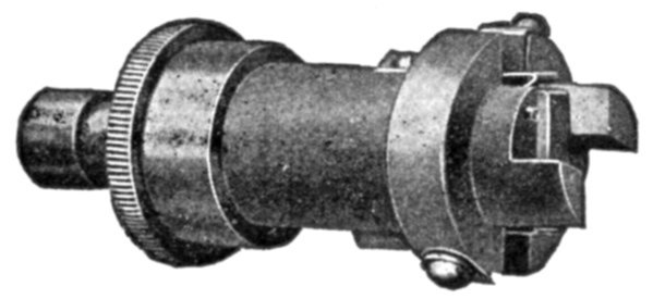
Fig. 2,274.—General Electric circuit closing auxiliary switch. This switch closes when the circuit breaker opens, and may be used to announce the automatic opening of the circuit breaker through the means of an indicating lamp or an alarm bell. It is often necessary to arrange one circuit breaker so that, in opening, it will trip others. This may be accomplished by using a circuit closing auxiliary switch in connection with a low voltage or shunt trip attachment on the circuit breakers to be tripped. The construction of this type of switch is such that it may be opened by hand after the circuit breaker opens, but it is automatically reset when the circuit breaker is closed.
Relays.—Oil break switches and carbon break circuit breakers are commonly used to open electrical circuits at some given overload and on short circuit. To secure additional protection under a variety of abnormal conditions or to provide for a certain predetermined operation or sequence of operations, relays may be employed.
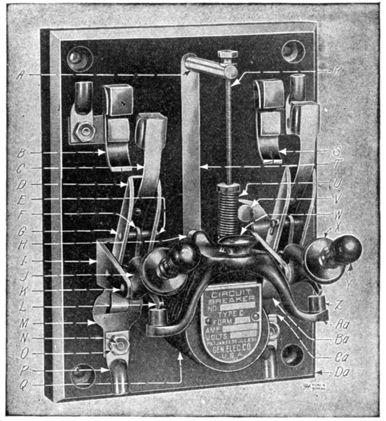
Fig. 2,275.—General Electric type C circuit breaker. Specially adapted to motor driven machine tool applications. For use in mills, machine shops, factories, foundries and office buildings. For general motor work, automobile charging outfits, storage batteries, rectifier sets, cranes, etc. List of parts: A, calibrating post; B, laminated contact; C, secondary contact spring; D, contact blade; E, cotter pin for G; F, toggle link; G, pin for D and F; H, stop for Aa; I, hinge frame; J, operating lever; K, pin for I and J; L, toggle link; M, connection; N, screw for M, O and P; O, nut for N and P; P, terminal; Q, tripping coil; R, calibrating screw; S, laminated contact; T, calibrating scale; U, calibrating spring; V, connection post; W, knob; X, washer for Y; Y, handle; Z, buffer; Aa, armature; Ba, laminated connection; Ca, connection; Da, base.
A relay is defined as: A device which opens or closes an auxiliary circuit under predetermined electrical conditions in the main circuit.
The object of a relay is generally to act as a sort of electrical multiplier, that is to say, it enables a comparatively weak current to bring into operation a much stronger current.
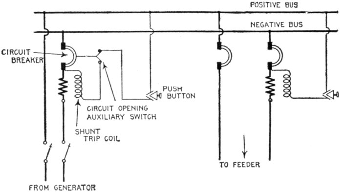
Fig. 2,276.—Diagram of connections of General Electric shunt trip coil with and without circuit opening auxiliary switch.
Ques. For what service are relays largely used?
Ans. They are employed in connection with high voltage switches where the small amount of energy derived from an ordinary instrument transformer is insufficient for tripping.
The connections between relays and circuit opening devices are usually electrical. Combinations of this nature are extremely flexible since they permit the use of a number of devices, each having a different function, with a single circuit breaker or oil switch as well as with two or more switches, to secure the desired operation and protection.
Selection.—In all electrical installations protection of apparatus is important, but in some large central stations this is secondary to continuity of service.
To combine maximum protection without interruptions of service is not always possible, but these requirements can be approximated very closely by the use of reliable and simple controlling or protecting devices if proper care be taken to select the relays suited to the special conditions of the installation. To do this intelligently, a knowledge of the various types of relay is necessary.
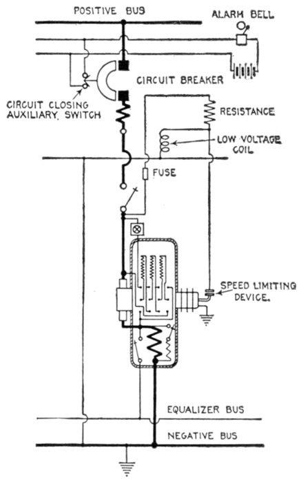
Fig. 3,073.—Diagram of connections of General Electric low voltage release coil when used with speed limiting device on rotary converter.
There is a multiplicity of types and a classification to be comprehensive, should, as in numerous other cases, be made from several points of view. Accordingly relays may be classified:
1. With respect to the nature of the service performed, as
a. Protective;
b. Regulative;
c. Communicative.
2. With respect to the operating current, as
a. Alternating current;
b. Direct current.
3. With respect to the manner of performing their function, as
a. Circuit opening;
b. Circuit closing.
4. With respect to the operating current circuit, as
a. Primary;
b. Secondary.
5. With respect to the abnormal conditions which caused them to operate, as
a. Overload;
b. Underload;
c. Over voltage;
d. Low voltage;
e. Reverse energy;
f. Reverse phase.
6. With respect to the time consumed in performing their function, as
a. Instantaneous (so called);
b. Definite time limit;
c. Inverse time limit.
7. With respect to the character of its action, as
a. Selective;
b. Differential.
8. With respect to whether it acts directly or indirectly on the circuit breaker, as
a. Main;
b. Auxiliary.
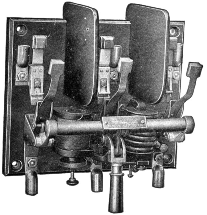
Fig. 2,278.—General Electric overload and low voltage type C circuit breaker for 600 volts or less. It has one overload, and one low voltage coil as shown. Screens are provided between contacts.
Protective Relays.—These are used to protect circuits from abnormal conditions of voltage, or current, which would be undesirable or dangerous to the circuit and apparatus contained therein.
Ques. How do protective relays operate?
Ans. They act in combination with automatic circuit breakers, operating when their predetermined setting has been reached, energizing the trip coil of the circuit breaker and opening the circuit.
Fig. 2,279 shows the principles of relay operation. When the current or pressure in the main circuit reaches the predetermined value at which the protective system should operate, the relay magnet attracts the pivoted contact arm and closes the auxiliary circuit; this permits current to flow from the current source in that circuit and energize the trip coil thus opening the main circuit.
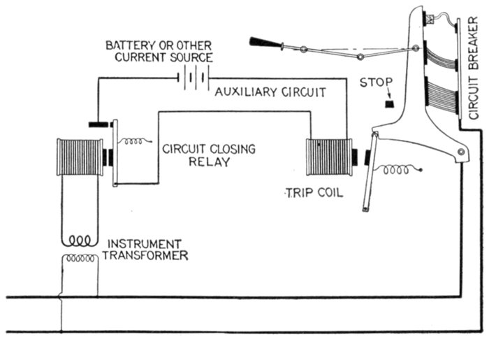
Fig. 2,279.—Diagram illustrating the operation of a circuit closing relay. When the predetermined abnormal condition is reached in the main circuit, the relay closes the auxiliary circuit, thus energizing the trip coil and opening the breaker.
Regulative Relays.—This class of relay is used to control the condition of a main circuit through control devices operated by a secondary circuit.
Ques. For what service are relays of this class employed?
Ans. They are used as feeder circuit or generator regulators.
Ques. How do they differ from protective relays?
Ans. They have differentially arranged contacts, that is to say, arranged for contact on either side of a central or normal position.
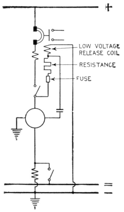
Fig. 2,280.—Diagram showing a railway synchronous converter protected by a single pole overload circuit breaker with low voltage release attachment and bell alarm switch. The low voltage attachment trips the breaker on failure of direct current voltage also when speed limit device closes. Internal troubles are taken care of by the alternating current automatic devices (not shown).
Communicative Relays.—These are used for signalling in a great variety of ways for indicating the position of switching apparatus or predetermining the condition of electric circuits.
A. C. and D. C. Relays.—As here used, the classification refers to the kind of current used on the auxiliary circuit. In some cases direct current is used to energize the trip gear of the circuit breaker or oil switch, and in others, alternating current.
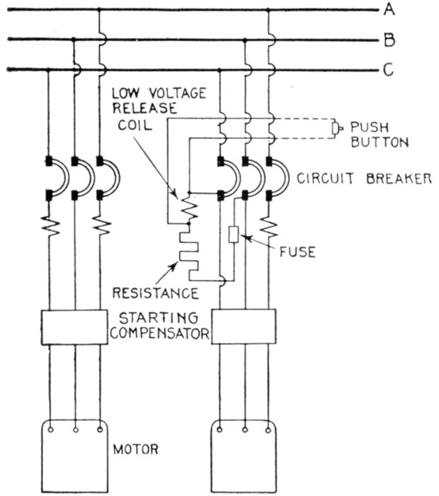
Fig. 2,281.—Diagram showing three phase motors protected by triple pole overload circuit breakers, with two overload coils, also one overload coil and low voltage release coil. The use of the low voltage release allows the breaker to be tripped from a distance by means of a short circuiting switch or push button.
A. C. and D. C. relays are respectively known as circuit opening and circuit closing relays, being later fully described.
Circuit Opening Relays.—The duty of a circuit opening relay is to open the auxiliary circuit, usually alternating current, nd thereby cause the oil switch or circuit breaker to be opened by the use of a trip coil in the secondary of a current transformer, or by low voltage release coil.
The trip coil of the breaker is generally shunted by the relay contacts and when the moving contact of the relay disengages from the stationary contact, the current from the transformer which supplies the relay, flows through the trip coil thus opening the breaker. These features of operation are shown in fig. 2,282.
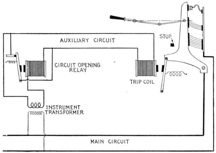
Fig. 2,282.—Diagram illustrating the operation of a circuit opening relay. When the relay contacts are in the normal closed position, as shown, the coil is short circuited. When the predetermined abnormal condition is reached in the main circuit, the relay contacts are opened with a quick break, sending the current through the trip coil momentarily, and opening the breaker.
Ques. Where are circuit opening relays chiefly employed?
Ans. In places where direct current is not available for energizing the trip coil.
Ques. What is the objection to alternating current trip coils?
Ans. They have relatively high impedance and impose a heavy volt ampere load on the transformers.
Circuit Closing Relays.—The duty of a circuit closing relay is to close the auxiliary circuit at the time when the predetermined abnormal condition is reached in the primary circuit. The closing of the auxiliary circuit energizes the trip coil and opens the breaker.
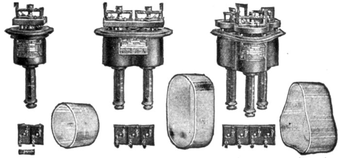
Figs. 2,283 to 2,291.—General Electric instantaneous overload circuit opening relays, covers removed. Circuit opening relays are used chiefly in those cases where direct current for the tripping circuit is not available. Alternating current trip coils have relatively high impedance and impose a heavy volt ampere load on the current transformers. To reduce this load during normal operation the circuit opening relay is frequently used and is usually necessary where instruments and meters are to be operated on the same current transformers as the trip coils if the greatest accuracy be required. The relay contacts in the normal, closed position, short circuits the trip coil. When the relay operates on overload or other abnormal condition the contacts are opened with a quick break, sending the current through the trip coil circuit momentarily and tripping the switch. With circuit opening relays, the trip coils of the oil switch must be set to trip somewhat lower than the setting of the relay. In construction the relay consists of a solenoid with iron frame forming the support for the relay; a central plunger or armature of special construction which is picked up or released by the magnetic action of the solenoid; a plunger rod which actuates the relay contacts, which are mounted on an insulated base usually above the solenoid; a tube or plate for the calibration marking and adjustment; covers of glass or metal to keep out dust; terminal boards with points corresponding to tagged leads from relay coils and external wiring diagrams. The relay contacts are of two kinds, circuit opening, as shown above, and circuit closing, as shown in figs. 2,292 to 2,300.
Ques. What kind of current is generally used for the auxiliary circuit of a circuit closing relay?
Ans. Direct current.
Ques. At what pressure?
Ans. From 125 to 250 volts.
Ques. Where is this current usually obtained?
Ans. From a storage battery, or from the exciter.
Ques. For what current are the contacts ordinarily designed?
Ans. About 10 amperes.
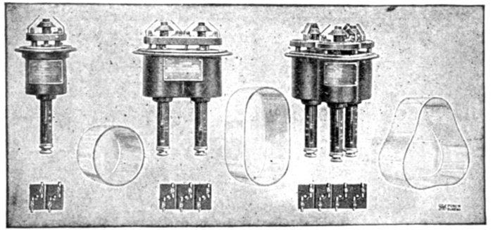
Figs. 2,292 to 2,300.—General Electric alternating current, instantaneous overload circuit closing relays, covers removed. The function of a circuit closing relay is to close an electrical circuit, usually direct current, through a trip coil on an oil switch or circuit breaker, or it may short circuit a low voltage release coil, and thereby open the oil switch or circuit breaker on occurrence of the condition upon which the relay is designed to operate. Direct current at 125 or 250 volts taken from exciter bus bars or storage battery system is generally used for the tripping circuit. Circuit closing contacts have a cone shaped central element of carbon or metal which makes contact with flexible contact fingers symmetrically arranged above the cone. These contacts will make and break a circuit of 10 amperes at 125 volts without the use of auxiliary circuit opening switches. Relays are made with two or three contacts for connecting one side of a direct current circuit through one or two separate circuits, or trip coils respectively, to the side of opposite polarity. Usually only two contacts are required. Where two or more trip coils are used, which may not be connected permanently in parallel, the three contact relays are selected and in some cases four contacts furnished.
Primary and Secondary Relays.—Primary relays are sometimes called series relays as they have the current coils connected directly in series with the line, both on high and low tension circuits.
Secondary relays receive their current supply from the secondary circuits of current transformers. Alternating current relays connected to secondary of pressure transformers and relays with both current and pressure windings are included in this class.
Ques. What is the usual winding of the coils?
Ans. The current coils are usually wound for 5 amperes and the pressure coils for 110 volts.
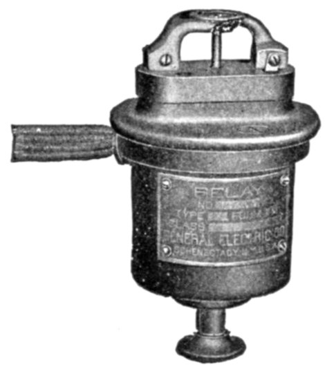
Fig. 2,301.—Alternating current low voltage circuit closing low voltage relay, for 600 volts or less. The contacts are similar to those of the circuit closing overload type except that they are inverted. As long as the pressure is normal the contact cone is held above the contacts. When the pressure falls below one half normal, the cone and plunger rod drop and close the contact. This relay does not pick up its own plunger. The plunger rod is pushed up by hand after the pressure circuit is established. Low voltage relays are generally used in connection with a low voltage release or shunt trip coil on an oil switch or a circuit breaker. They are used in connection with motor booster sets to prevent a disastrous speed of the booster which might result from the loss of alternating current power. They are also sometimes used for indicating purposes.
Ques. What refinement is made in the design of relays and why?
Ans. Care is exercised to reduce to a minimum the volt ampere load imposed by the relay on the current transformer to permit the use of un-stranded meters and relays upon the same transformer.
The use of circuit opening relays to cut out the trip coil of an oil switch during normal operation, has been described, and in the short time that the trip coil is in circuit, it does not affect the accuracy of the instrument readings. This practice, however, does not apply in the case of curve drawing meters, voltage compensators or other devices which have in themselves sufficient load for separate current transformers. In this connection it should be noted that to obtain accurate instrument and meter readings; the current transformers should not be loaded beyond certain limits which depend upon the volt ampere load and power factor of each of the connected devices.
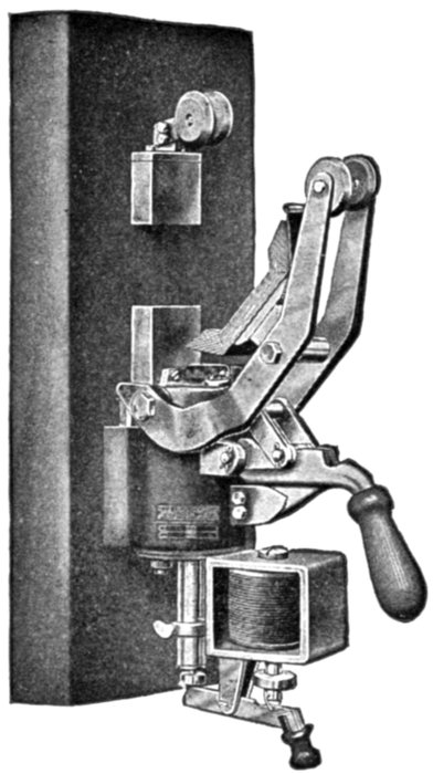
Fig. 2,302.—Condit type K circuit breaker with shunt trip and no voltage attachment. The shunt trip is usually applied as an auxiliary to other types of trip. It consists of a fine wire coil which is mounted as a self-contained part of the breaker and which when energized, trips the circuit breaker. It is used to open the breaker from some distant point, and the coil is arranged to be connected across the line. The coils are so arranged that the circuit breakers will operate on a voltage 25% above or 25% below normal. The shunt trip coil is not intended to remain across the line and should be only momentarily energized. The no voltage trip, receives energy from a high resistance or fine wire coil which is arranged to be placed directly across the line, but in contradistinction to the shunt trip type, in which the coil is momentarily energized to trip the breaker, the no voltage coil is constantly energized and a decrease or failure of pressure trips the breaker. It can be used as a remote control device the same as the shunt trip. Its general use, however, is to cause the circuit breaker to open when the voltage of the line fails from any cause. Its use is recommended on all motor circuits, as it affords an additional protection against accidents, for if the voltage should fail, the breaker immediately opens, and before the machine can start again the attendant must close the breaker. It will not work for the protection of storage batteries or of motor generator sets charging storage batteries, as, when the voltage of the generator fails, the voltage of the battery still maintains its full value. The action of the coil is independent of the direction of flow of current; it simply allows the breaker to stay closed as long as the voltage is on the line and opens the breaker when the voltage on the line ceases. No voltage circuit breakers are normally so adjusted that they will not release until the voltage approaches 50% of normal.
So great is the variety of combination used and the variations of these factors in their several combinations at different loads and settings, that special consideration of each arrangement is advisable.
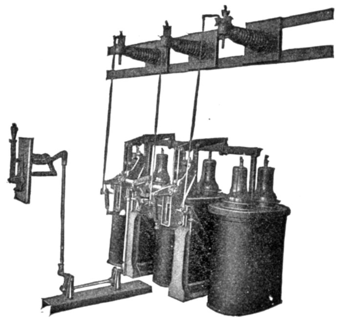
Fig. 2,303.—General Electric alternating current high pressure series overload relays controlling 45,000 volt oil switches. These relays are connected in series with the line. If current transformers are to be used on the same circuit for other purposes, and have sufficient capacity to supply energy for operating relay coils, then secondary relays would be more economical, otherwise the series relays are much less expensive. By means of a specially treated wooden rod, the relay operates a tripping switch, closing a separate tripping circuit, usually 125 or 250 volts direct current. Relays and switches are for mounting on flat surfaces. Series relays are essentially the same as secondary relays except in the coil winding and insulation. The corrugated horizontal arms which carry the relays, as shown, are insulated posts, insulating the relays from the ground. The wood rod from each relay is connected directly to a tripping shaft on the oil switch which buckles an auxiliary toggle, thereby opening the main toggle and tripping the oil switch.
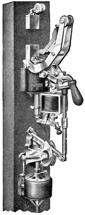
Fig. 2,304.—Condit 600 volt, 1,500 ampere single pole back connected type K circuit breaker, motor operated. The mechanical and electrical features of the circuit breakers are no different than when hand operated, the only difference being that the motor is used for the operating means. This motor is so arranged that even should it over travel, due to an accident to the controlling circuit, it cannot produce more than a predetermined strain on the circuit breaker. In other words, after the motor has closed the circuit breaker, further travel of the motor will not result in putting a strain on the operating parts. Suitable motors are supplied for this service, the type of motor varying in accordance with the character of the operating current supplied. The advantage of this type of electrical operation is that it puts very little strain on the switch mechanism, takes very little operating current, allows the use of standard parts, and makes an extremely substantial and flexible structure. Its disadvantage is that it closes slowly, and it must not, therefore, be used in places where quick closing is essential.
Overload Relays.—Series relays are connected directly in series with the line and are chiefly used with high pressure oil break switches for overload protection. If current transformers are to be used on the same circuits for other purposes, and have sufficient capacity to admit of adding a relay coil, secondary relays would be more economical; otherwise, the series relays are less expensive.
By means of a specially treated wooden rod, the relay operates a tripping switch, closing a separate tripping circuit, usually 125 or 250 volts direct current. Series relays are essentially the same as secondary relays except in the coil winding and insulation.
Underload Relays.—These are similar in construction to low voltage relays but have current instead of pressure windings.
Over Voltage Relays.—These are usually of the circuit closing type and are similar to secondary overload relays, but have pressure instead of current windings.
Low Voltage Relays.—Relays of this class are in most cases used
for the protection of motors in the event of a temporary weakening or failure of the pressure. They are also used in connection with a low voltage release or shunt trip coil on an oil switch or a circuit breaker.
Reverse Energy Relays.—The chief object of this species of relay is to protect the generator. When so used, the overload adjustment is set at the maximum value to give overload protection only at the maximum carrying capacity of the generator and a sensitive reverse protection to prevent a return of energy from the line.
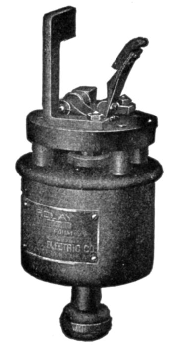
Fig. 2,305.—General Electric direct current solenoid control relay. Solenoids for operating large switches, etc., frequently require comparatively large operating currents in the "closing" coils. This necessitates the use of relatively heavy leads between the control switch and the solenoid and is the cause of severe arcing at the control switch, especially with solenoids of high inductance. These objectionable features can best be eliminated by the use of a suitable control relay located near the solenoids. The control relay consists of a solenoid plunger and switch, the latter insulated from the frame of the relay. It operates satisfactorily on one-half the rated voltage and requires only a very small operating current. The terminals of the switch and the relay coils are independent. The relay can be wound for operation on 125, 250, or 600 volt circuits.
Reverse Phase Relays.—This type of relay is used chiefly to prevent damage in case of reversal of leads in reconnecting wiring to two or three phase motors.
Time Element.—It is often inconvenient that a circuit breaker should be opened immediately on the occurrence of what may prove to be merely a momentary overload, so that time lag attachments are frequently provided, particularly with relays. These devices, which may form part of the relay or may be quite distinct from it, retard its action until the overload has lasted for a predetermined time—several seconds or more.
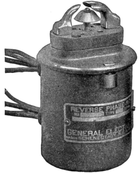
Fig. 2,306.—Alternating current series reverse phase single pole, circuit closing, two contact relay for 600 volts or less. This type of relay is used chiefly to open motor circuits for elevators to prevent damage in case of reversal of leads in reconnecting wiring to two or three phase motors. The relay is provided with a dust proof metal cover.
Ques. What should preferably govern the time lag?
Ans. It should depend on the extent to which the overload is reduced as the time elapses.
Instantaneous Relays.—The so called instantaneous relays operate almost instantly on the occurrence of the abnormal condition that they are to control.
There is of course a slight time element comparable with that of an overload circuit breaker, but for practical purposes, the operation may be considered as instantaneous.
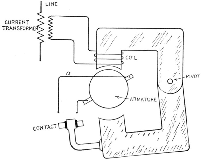
Fig. 2,307.—Electric circuits of Condit type "A" relay. The construction is described in fig. 2,309. As here shown, the relay is not in operation, but should the current passing through the coil be of sufficient value to cause the lower movable half of the magnetic circuit to approach the upper stationary half of the circuit, the relay will be transformed from an ordinary electromagnet into a repulsion motor. The contact will short circuit the brushes of the armature and thus cause it to revolve, the speed of rotation being dependent on the amount of current flowing to a predetermined point, and thereafter the speed of rotation of the motor remains constant irrespective of the current value. Time adjustment: This is obtained by varying the distance through which the contact travels, provision being made whereby adjustment can be made as close as .1 of a second. Current adjustment: This is obtained by means of a calibrated spring. Standard relays are calibrated at 6, 8, 10, and 12 amperes, the coils being designed to carry five amperes continuously, with a temperature rise not exceeding 86° Fahr. Power to operate relay: The relay requires twenty volt amperes for its operation at full load; the influence of this type of relay on the ratio and phase angle of current transformers is small.
Time Limit Relays.—Under this classification there are two sub-divisions.
1. Definite time limit;
2. Inverse time limit.
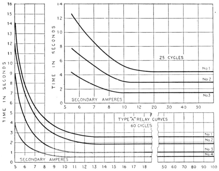
Fig. 2,308.—Characteristic curves of Condit type A selective relay. Curves 1, 2, 3, and 4 show the time variation of this relay with different settings at the various current values. The relay may be adjusted to trip the switch at any point represented between curves 1 and 4. This relay is a combination of an inverse time limit relay and a definite time limit relay. The combination of the characteristics of the two types are seen in the curve, the first part of which is inverse, and the latter part definite from a point of three or four times full load current. This combination of features being desirable as, for instance, in transmission work, particularly where it is necessary to use circuit breakers set selectively, as, due to the inverse feature of the curve, the relays can be set so that on a moderate overload, they will require the proper length of time to operate, and at the same time will operate quickly enough on heavy short circuits to prevent damage to the distribution system or its apparatus. Due to the definite feature of the latter part of the curve, the relays of the varying circuit breakers when once set to operate at different time values will never operate simultaneously irrespective of the value of the short circuit current, thus tending toward continuity of service.
Ques. Describe the time mechanism of a definite time limit relay.
Ans. It consists of an air dash pot, and an air diaphragm or equivalent retarding device connected to the contact mechanism.
Ques. How does it operate?
Ans. In some designs, when the contacts are released, they descend by gravity against the action of the retarding device thereby making contact a definite interval after the occurrence of the abnormal condition.
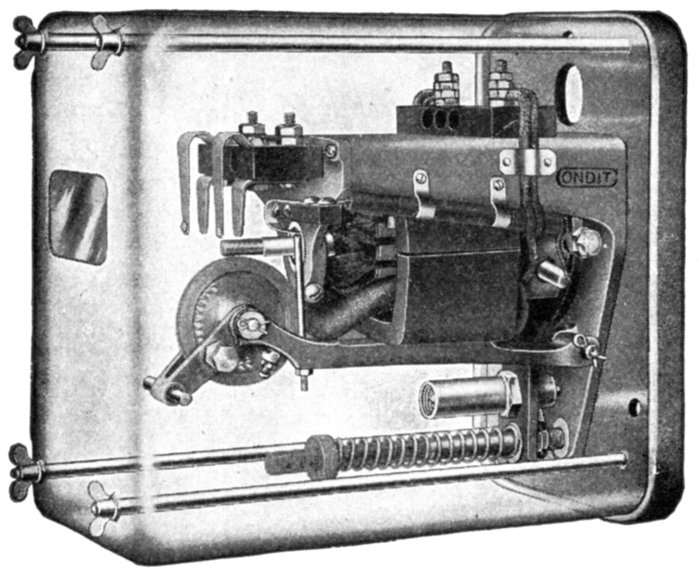
Fig. 2,309.—Condit type "A" selective relay, designed for use with circuit breakers where selective or discriminating action is required. The circuits and connections of this relay are illustrated in fig. 2,307, and its characteristics in fig. 2,308. In construction, the relay consists of a special motor with a short circuited armature and a split field. Under normal conditions, the fields are separated from each other and the motor armature does not revolve. The force tending to pull the two faces of the field together is opposed by a spring, the compression of which determines the number of amperes necessary to cause the relay to begin operation. The motor structure performs the whole work and the motor itself un-meshes and meshes the gears without the aid of any external device.
Ques. How does the inverse time limit type operate?
Ans. The actuating and contact mechanism is attached directly to an air bellows and in operation tends to compress the bellows against the action of a specially constructed escape valve in the latter.
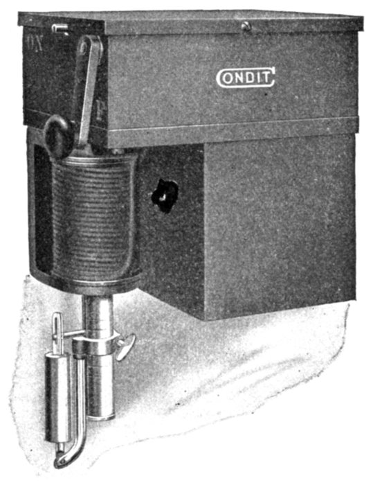
Fig. 2,310.—Condit type "B" time limit attachment, designed to give sufficient time to allow an induction motor to start without opening the circuit breaker, and not have the circuit breaker trip on the momentary rush of current. Its action is inverse; that is, the greater the current the less time it takes to operate and is so arranged that four to five times full load current or a short circuit will trip the circuit breaker instantly. The time limit attachment is applied directly to the armature which trips the circuit breaker and is adapted for the so called primary trip. It consists of an air vacuum dash pot with a graphite piston, the dash pot being fastened to the stationary calibrating ring of the trip coil and the moving outside cylinder is fastened to the armature of the circuit breaker. When the current reaches a point where it overcomes the weight of the armature and lifts the same, the magnetic force tending to raise the armature is opposed by the vacuum created in the interior of the cylinder. As the magnetic force continues the vacuum is overcome due to the leakage of air past the plunger and the armature gradually moves up until it reaches the point where it trips the circuit breaker. If at any point of the armature travel, the current drop back to normal, the armature immediately resets itself by means of a ball valve in the top of the brass cylinder.
Ques. Why is the arrangement called inverse time limit?
Ans. Because the retardation varies inversely with the pressure on the bellows, and therefore inversely with the magnitude of the abnormal condition.
Ques. What other device may be used to retard the operation?
Ans. A damping magnet is sometimes used which acts on a disc or drum and which may be adjustable.
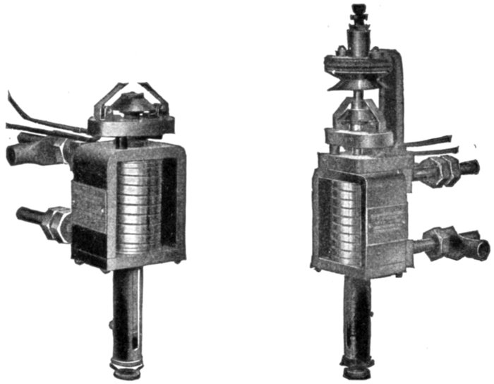
Figs. 2,311 and 2,312.—General Electric alternating current low pressure series overload relays. Fig. 2,311, instantaneous time limit relay; fig. 2,312, inverse time limit relay. These relays have carbon contacts and will make or break a direct current circuit of 10 amperes at 125 volts without auxiliary circuit opening switch. They are used where several circuits are controlled by one automatic oil break switch or one shunt trip, overload and shunt trip or low voltage release carbon break circuit breaker. These relays may be used for signal purposes; they are back connected, the connections can be seen in the illustrations.
Ques. How is the inverse time element introduced by this arrangement?
Ans. The retardation is due to eddy currents induced by moving the disc or drum through the magnetic field. The reaction thus induced varies inversely with the magnitude of the force with which the disc or drum is urged through the field and hence inversely with the abnormal condition.
Ques. What are the ordinary limits of adjustment for inverse time limit relays?
Ans. From one-half second to 30 seconds, depending upon the time setting and magnitude of the overload current.
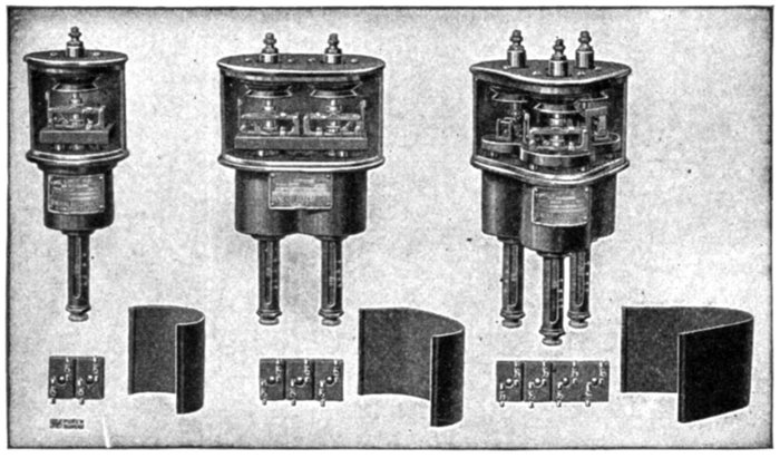
Figs. 2,313 to 2,321.—General Electric time limit overload circuit opening relays with covers removed. The construction of this relay is similar to that of the inverse time limit relay, except that it has a compression spring interposed between the plunger and diaphragm. The plunger compresses the spring and further motion is prevented by a stop, making the relay practically independent of the amount of the overload, only the stored energy of the spring, if the overload continue, applies power, dependent on its own mechanical strength, to the diaphragm. The time limit therefore becomes practically a constant for any given setting under ordinary conditions of overload or short circuit. If, however, the overload come on slowly so that the spring is not fully compressed at once, the time limit will vary slightly. If the scheme of selective operation make it necessary to take care of a creeping load of this character, two relays may be used and definite time limit positively secured. In this case, an instantaneous circuit closing, overload relay would be used and a definite time limit relay, provided with a direct current coil in circuit with the closing contacts of the first relay. The time limit relay would be of the circuit closing type and control a direct current trip coil on the oil switch.
A setting of from two to six seconds is ordinarily used, depending upon the requirements. Where selective operation is desired a minimum setting of two seconds is recommended.
Differential Relays.—In this type of relay there are two electromagnets. In normal working these oppose and neutralize each other. Should, however, either winding become stronger or weaker than the other, the balance is upset, the magnet energized, and the relay comes into operation.
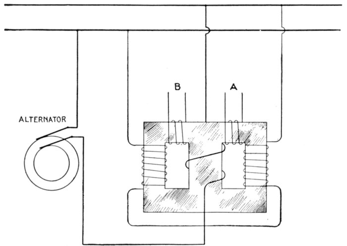
Fig. 2,322.—Differential relay transformer and reverse current circuit breaker discriminating device. A differential relay is one whose electromagnet has two windings. In normal working these oppose and neutralize one another. Should however, either winding become stronger or weaker than the other, the balance is upset, the magnet is energized, and the relay comes into operation. A modification of such a relay for alternating current is here shown, from which it will be seen that when the currents are as indicated, the circuit A has the larger pressure induced in it, whereas, should the main current reverse with reference to the shunt current, the circuit B would have the larger induced pressure.
A modification of such a relay for alternating current is shown in fig. 2,322, from which it will be seen that when the currents are as indicated, the circuit A has the larger pressure induced in it, whereas, should the main current reverse with reference to the shunt current, the circuit B would have the larger induced pressure.
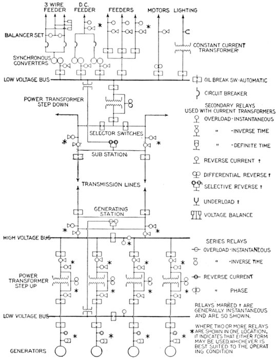
Fig. 2,323.—Diagram of modern power house wiring and busses showing location of relays.
[1]How to Select Relays.—The following general information on relays, together with reference to the one line diagram, fig. 2,323, will be of interest and assistance in making a selection from the various relays previously described to meet the requirements of modern power house and sub-station layouts.
Single pole relays are used on single phase and on balanced three phase circuits.
Double pole relays are used on ungrounded three phase and on quarter phase.
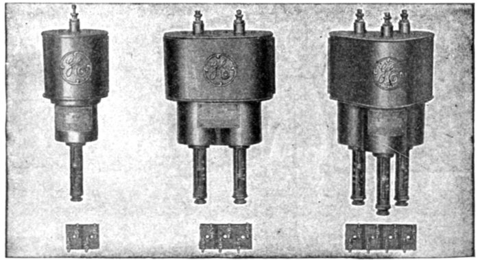
Fig. 2,324 to 2,329.—General Electric inverse time limit overload circuit closing relays. In this type of relay its mechanism is so designed that a delay or lapse of time in opening the circuit breaker after a predetermined condition of the circuit has been reached, depends on the flow of current, that is, if the current be great, the time will be small, and if the current be of a moderate value, the time will be correspondingly longer.
Triple pole relays are used on three phase grounded neutral and interconnected quarter-phase.
Circuit closing relays are recommended in all cases where a constant source of direct current is available for operating trip coils.
The conditions for which relays have been designed for power circuits may perhaps be best described, by considering a one line diagram from the generator end to the sub-station auxiliary machines and feeders.
Considering first alternating current circuits, the prevailing practice is to make the circuit breakers by which the alternators are connected to the low tension bus non-automatic, in order to insure minimum interruption of alternator service. The chance of trouble in this part of the circuit is remote, but should it occur, the station attendant could generally open the circuit breaker before the machines would be injured.
Reverse current relays of instantaneous or time limit types are often connected to the secondaries of current and of pressure transformers to indicate by lamp or bell any trouble that may occur in the generator circuit.
These relays operate with a low current reversal at full pressure and conversely with a proportionally greater current at voltages less than normal. At zero pressure, the relay would act as an overload one, set for high overload. At zero current, a voltage considerably in excess of normal would be required to operate it.
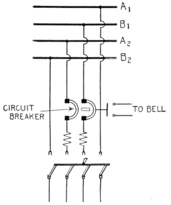
Fig. 2,330.—Diagram showing two phase motor or feeder circuit protected by double pole double coil, overload circuit breaker (or two single pole breakers interlocked) with bell alarm switch.
Specifications sometimes call for automatic generator circuit breakers: in this case definite time limit overload relays are used. They are connected in the secondaries of current transformers and are designed to give the same time delay for all trouble conditions; they allow the defective circuit to be opened, if possible, at a point more remote from the generator than the generator circuit breaker.
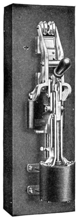
Fig. 2,331.—Condit 600 volt, 1,500 ampere, single pole type K circuit breaker pneumatically operated. It is the same as the electrically operated circuit breaker, except that a pneumatic cylinder mechanism is supplied in place of either the electromagnet or the motor. This cylinder mechanism is so arranged that the air pressure is only on the cylinder at the instant of operation. At all other times the air pressure is shut off by means of a control valve. The kind of remote control to be used depends on local conditions. In general, the hand operated remote control device is preferable where conditions are such that it can be used, and where it is necessary to use electrically operated, the motor operated type is recommended if conditions be such that slow closing is not objectionable.
When the total generator capacity exceeds the rated rupturing capacity of the circuit breakers, one or more sectionalizing circuit breakers are placed in each bus.
If operating conditions admit, these devices are made non-automatic and are left disconnected except in case of emergency; but if it be necessary for them to be continually in service, they may be made automatic by means of instantaneous overload relays connected to current transformers in the low voltage bus; the relays being adjusted to trip the circuit breaker under short circuit conditions, confining the trouble to one section and preventing the circuit breakers rupturing more than their rated capacity.
Installations with but one bank of power transformers, and without high voltage bus, are provided with automatic circuit breakers operated by an inverse time limit relay.
The relay is connected to the secondaries of current transformers, which in turn are connected in the low voltage side of the power transformer.
Stations with more than one bank of power transformers, a high voltage bus, and high and low voltage circuit breakers, may have both circuit breakers arranged to trip at the same time or one after the other. As in the former case, they are operated from the inverse time limit relay connected in the low voltage side.
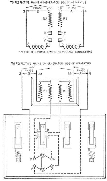
Figs. 2,332 and 2,333.—Diagram showing two phase four wire no voltage connections for I-T-E circuit breaker. The two no voltage coils for two phase four wire circuits are connected respectively to binding posts B, C and A, D on the face of the base. B and D are connected to lower spring contacts 2 and 1 respectively, of the small disconnecting switch. (In instruments supplied on individual bases, these connections are made in the factory, let into channels in back of base and covered with wax.) Each of the upper contacts a and b of the disconnecting switch is connected respectively through resistance R2 and R1 to one main in each phase at aa and bb. C and A are respectively connected to the other main in each phase at 3 and 4. Thus each of the no voltage coils operates across one phase independent of the other. The terminals 3, aa, bb and 4, must, in all cases, be so connected that they will be subject to the full voltage of the circuit, irrespective of the position of the starting switch.
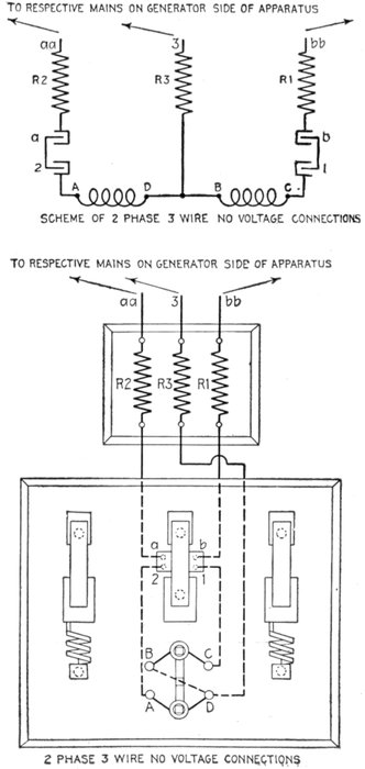
Figs. 2,334 and 2,335.—Diagram showing two phase three wire no voltage connections for I-T-E circuit breaker. The two no voltage coils for two phase, three wire circuits are connected respectively to binding posts B, C and A D on the face of the base, and from A and C connections are made to lower contacts 2 and 1 respectively of the disconnecting switch. Binding posts B and D are connected together on the back of the board. (In instruments supplied on individual bases, these connections are made in the factory, let into channels in back of base and covered with wax.) Each of the upper contacts a and b is connected respectively through resistance R2 and R1 to one of the mains at aa and bb as shown. D is connected through resistance R3 to the common wire of both phases at 3 B and D being connected as aforesaid, thus forming a common connection for both no voltage coils. Terminals aa and bb of the resistances must be connected to the outside main across the two phases, terminal 3 to the main common to both phases, the connections being so made that these terminals will be subject to the full voltage of the circuit irrespective of the position of the starting switch.
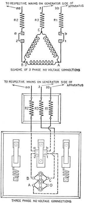
Fig. 2,336 and 2,337.—Diagram showing three phase no voltage connections for I-T-E circuit breaker. The no voltage coils for three phase circuits are connected in Δ by means of binding posts A, B, C and D on the face of the base, and from the A and B of the no voltage coils, connections are made respectively to spring contacts 1 and 2 of the small disconnecting switch. Each of the contacts a and b of the disconnecting switch is connected respectively through resistance R2 and R1 to one of the mains at aa and bb. The terminal C is connected through resistance R3 on the back of the board to the middle main as shown at point 3. The terminal D is linked on the back of the board to terminal B to complete the [Greek: D
connection. The terminals aa, bb and 3 of the circuit breaker must, in all cases, be so connected that they will be subject to full voltage of the circuit irrespective of the position of the starting switch. Each no voltage coil is supplied with two terminal wires, one covered with green and one with black insulation. In replacing these coils particular care should be taken to see that the terminal wires connected to any one binding post are of unlike color.]
In plants in which two or more banks of transformers are operated in parallel between high and low voltage busses, it is desirable to have for each transformer bank, an automatic circuit breaker equipment which will act selectively and disconnect only the bank in which trouble may occur. With a circuit breaker on each side of transformer bank, selective action may be secured in two ways as follows:
1. By means of an instantaneous differential relay connected in the secondaries of current transformers installed on both the high and low voltage sides of each transformer bank.
The relay operates on a low current, reversal on either side of the bank.
2. By means of one inverse time limit, secondary or series relay installed on that side of the transformer bank which is opposite the source of power, the relay being arranged to trip both the high and low voltage circuit breakers.
The first method has the disadvantage of high first cost due to the high voltage current transformers required, but is more positive than the second method and is independent of the number of transformer banks in parallel.
The second method is the less expensive of the two and protects against overloads as well as short circuits in the transformers, but it is less positive and introduces delay in the disconnection of the transformer when trouble occurs. Furthermore, it is not selective when less than three banks are operating in parallel.
The automatic circuit breakers in the outgoing line may be operated from inverse time limit relays connected in the secondaries of current transformers; or in case transformers are not necessary for use with instruments, series high voltage inverse time limit relays connected directly in the line may be used.
Whether to select current transformers with relays insulated for low voltage, or to choose series relays, is a question of first cost and adaptability to service conditions. Below 33,000 volts, the commercial advantages in favor of the series relay are slight, and since it is somewhat difficult to design this device for the large current capacities met with at the lower voltage, it is generally the practice to use the relay with current transformer, because of its operating advantage. This practice, however, is not entirely followed, since some service conditions (described later) make the use of series relays very desirable and practical.
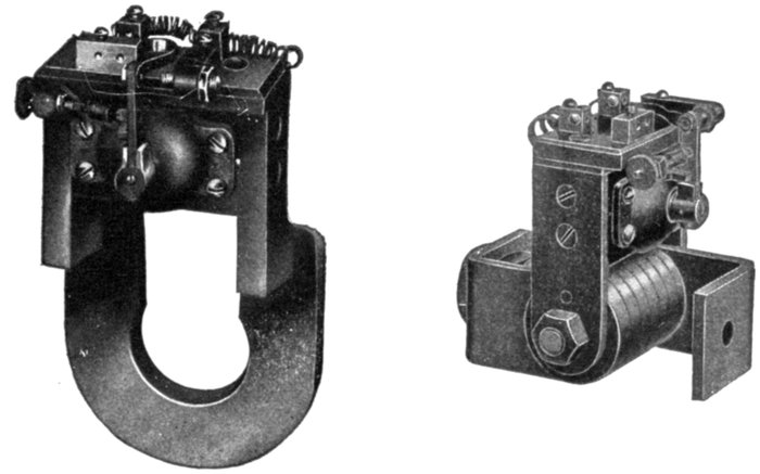
Figs. 2,338 and 2,339.—General Electric instantaneous direct current reverse current or "discriminating" relays. Fig. 2,238, for 500 amperes; fig. 2,339 for 2,000 amperes. These relays are designed for mounting directly on circuit breaker studs. These relays consist of a horseshoe magnet with a shunt wound armature pivoted between its poles. The magnet is mounted on the current carrying stud of the circuit breaker between the back of the panel and the first contact or supporting nut, and is placed in a vertical position. The contacts are insulated from the magnet permitting the use of an auxiliary circuit for the tripping device, independent of the circuit controlled by the circuit breaker. The magnet is excited by the current flowing through the stud, and the armature is connected across the line in series with suitable resistance. Rotation of the armature in the normal direction is prevented by a stop. Reversal of the current flowing through the stud changes the direction in which the armature tends to rotate, causing it to move away from the stop and close the circuit through an auxiliary trip coil and trip the circuit breaker. These relays are used to protect dynamos, storage batteries, or main station busses from damage on reversal of current due to short circuit, or from the grounding of machines or connection. Relay contacts must not be used to open the shunt trip coil circuits. An auxiliary switch should be provided for this purpose in all cases where the opening of the circuit breaker does not disconnect the trip coil from the source of supply.
Inverse time limit relays are satisfactory for one, or more than two outgoing lines in parallel as they act selectively to disconnect the defective line only, but installations with only two outgoing lines in parallel have the same load conditions in both lines and selective tripping of the circuit breakers in the defective line is obtained by means of a selective relay acting instantaneously under short circuit conditions only.
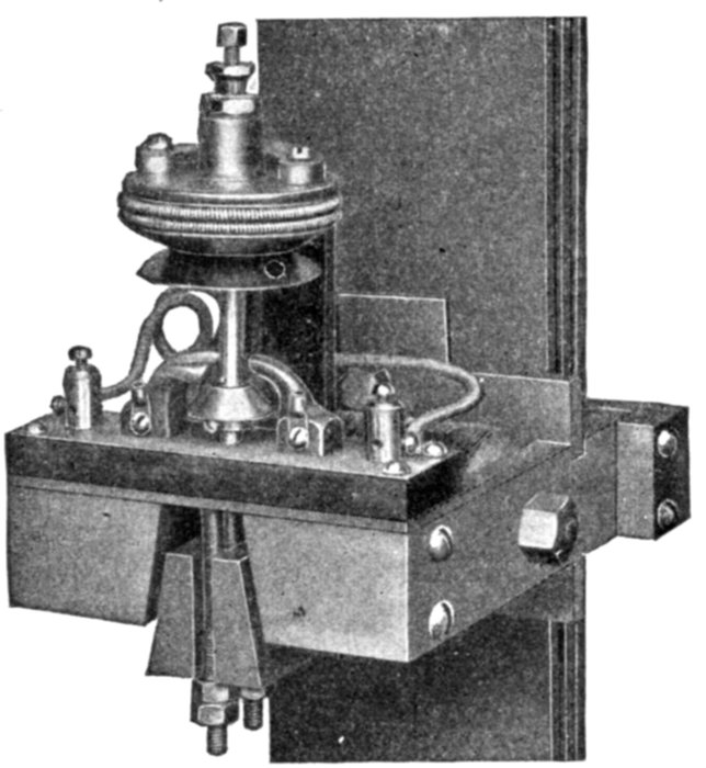
Fig. 2,340.—General Electric direct current, reverse current relay, used to protect dynamos, storage batteries, or main station busses from damage on reversal of current due to short circuits or from the grounding of machine or connections. It is mounted on vertical bus bars as in the case of cables, on the side wall, or other flat surface, and the cables threaded through the frame. When used to trip a circuit breaker, the breaker is provided with a shunt trip connected across the circuit, the tripping circuit being closed through the relay contacts on the occurrence of sufficient reverse current to lift the relay armature. The relay is either instantaneous or time limit as desired. In the time limit relay, the time interval is obtained by the leather bellows shown in the illustration. The time setting can be varied within certain limits by means of a valve on the bellows outlet. The operation of the relay depends on the relative value and direction of magnetic flux set up by a pressure coil, shown in the illustration, and the current in the vertical bars. Under normal conditions these fluxes are in the same direction and circulate around a closed magnetic circuit. When the current in the bars reverses, the two fluxes oppose each other and force flux through the normally open leg of the magnetic circuit. When the reversal of current is of predetermined value, the relay armature is lifted and the purpose of the relay accomplished.
The relay design and action is similar to the reverse current relay previously mentioned, and is connected to the secondaries of current transformers in each high voltage line and pressure transformers in the low voltage bus.
In the sub-station, the conditions are the reverse of those in the main station, the incoming lines becoming the source of power.
If there be only one incoming line and no high voltage bus, the line circuit breaker is generally non-automatic. With one incoming line and high voltage bus, the circuits from the service side of the bus are equipped with automatic circuit breakers and relays. These relays and those used for other arrangements of two or more incoming lines in parallel, as well as high and low voltage circuit breakers, are of the same design and are applied in the same manner as for the generating station.
Regarding the relay equipments for auxiliary machines, the same practice is recommended with the generator end of alternating current motor generator sets as with the main generators, the outgoing feeder circuit breakers being tripped from inverse time limit or instantaneous relays.
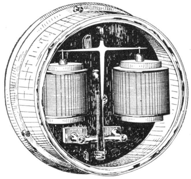
Fig. 2,341.—General Electric direct current differential relay for balancer set; instantaneous, 500 (or less) volt type for mounting on panel. In many power plants direct current, three wire, power service is furnished by "high voltage" two wire dynamos operating in connection with balancer sets consisting of two "low voltage" machines on a common shaft. With this combination of machine, a short circuit or heavy overload on one side of the system will shift the neutral considerably, and the lamps on the opposite side may "burn out". To protect the lamps, a differential relay operating on 15 volts unbalancing, is commonly used; it is connected to trip either the dynamo's circuit breakers (or a circuit breaker connected in the bus between the balancer set and the other dynamos).
With several synchronous machines in parallel, the relays are arranged to operate with the least time delay with which it is possible to get selective action, in order to prevent the machines being thrown out of step in event of trouble conditions causing a decrease of voltage.
The various types of induction motor and various conditions under which they are employed, have brought about the development of several types of relay to protect the motors and the apparatus with which they are used.
It is desirable to disconnect a large motor in case of voltage failure, and with conditions requiring either a motor operated, or a solenoid operated circuit breaker, a low voltage relay is used to close the tripping circuit whenever the voltage decreases to, approximately, 50 per cent. below normal.
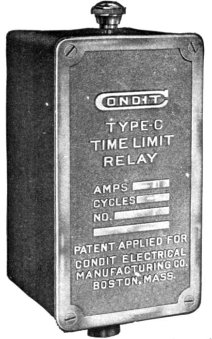
Fig. 2,342.—Condit time limit relay, designed primarily for use in connection with feeder circuits, where close selection or discrimination of circuit breakers is not required. It may be used satisfactorily on lighting and power circuits and also where there are sudden, momentary fluctuations of current. This relay is used in connection with series transformers. The contact arrangements are provided so that the relays may be used as circuit closing or circuit opening relays. The delayed action is produced by an air vacuum dash pot with a graphite piston. The piston of the dash pot is connected to an arm arranged to be moved by the armature. When the current reaches a point where it overcomes the weight of the armature and lifts the same, the magnetic force tending to lift the armature is opposed by the pull of the vacuum created in the interior of the shell into which fits the graphite piston. As the magnetic pull continues the vacuum is overcome due to the leakage of air past the piston, and the armature gradually moves until it reaches a point where it causes the circuit breaker to trip, either by closing the contacts in the circuit closing type, or by opening the contacts in the circuit opening type. If, at any portion of its travel, the current drop to normal, the armature immediately resets. The time adjustment consists of an arrangement whereby the distance through which the armature moves before tripping the breaker, may be changed, thus altering the time of tripping. The current adjustment is made by changing the effective turns of the actuating coil, the travel of the armature and the force exerted by it being the same for all current adjustment. The winding is designed to carry 5 amperes continuously with a temperature rise not exceeding 68° Fahr. standard calibration is provided so that the relay will start to operate at 5, 6, 8 and 12 amperes.
Up to 550 volts, these relays may be connected across the line, but for higher voltages they are connected to secondaries of pressure transformers. Smaller motors with which hand operated circuit breakers are used, are generally provided with low voltage release attachments that perform the same function as the relay.
Induction motors are sometimes subjected to high voltage conditions and to protect them from injury, high or excess voltage relays are employed to trip the automatic circuit breaker. These relays are of similar design and wired in the same manner as the low voltage relays.
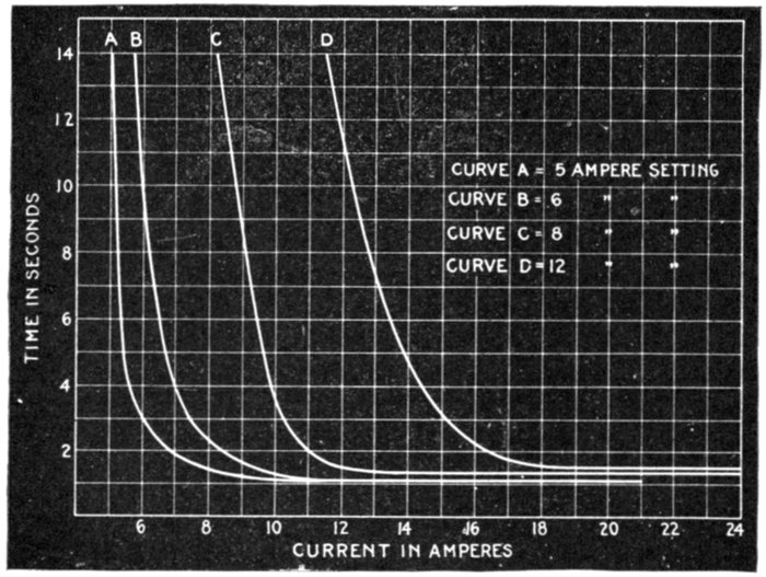
Fig. 2,343.—Characteristic curves of Condit time limit relay as illustrated in fig. 2,342. Settings: curve A, 5 amperes; curve B, 6 amperes; curve C, 8 amperes; curve D, 12 amperes.
Reverse phase relays have been developed for operating conditions under which a reversal of phase would cause trouble, as for example, in the case of elevator motors.
These are so designed that any phase reversal that would reverse an induction motor, would operate the relay and disconnect the automatic circuit breaker.
The design is based on the principle of the induction motor, and in the case of low voltage motors of limited capacity, the relay may be connected in series in the motor leads. If the voltage or capacity of the motor make this arrangement inexpedient, the relay may be placed in the secondaries of current or pressure transformers connected in the motor leads.
Underload relays are often used to trip the automatic circuit breaker that is placed in the primaries of arc lighting circuits to prevent an abnormal rise of secondary voltage in case of a break in the secondary circuit.
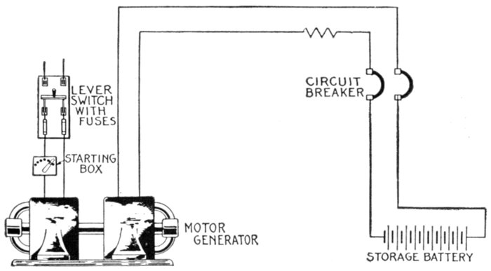
Fig. 2,344.—Diagram showing storage battery and charging dynamo protected by double pole single coil underload circuit breaker. In operation, the circuit breaker disconnects the battery when fully charged, and protects the dynamo from reverse current.
The underload relay is similar in design to the low voltage relay excepting that it acts on a decrease of current.
The problem of protecting induction motors, from injury, that may result from running on single phase, or from an overload, and at the same time permit the motor to be started with the necessarily high starting current that may be greatly in excess of the overload current, has caused the development of the series relay.
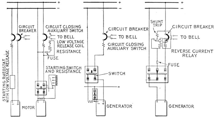
Fig. 2,345.—Diagram showing direct current motors protected by overload circuit breakers with bell alarm switches: a, double pole single coil breaker no switch required. Low voltage device is on the starting rheostat; b, single pole breaker in series with lever switch. Low voltage attachment on the breaker.
Fig. 2,346.—Diagram showing two wire dynamo, protected by a single pole overload circuit breaker with bell alarm switch. Breakers must be on opposite side from the series field.
Fig. 2,347.—Diagram showing dynamo protected by a single pole overload circuit breaker with reverse current relay and combined circuit opening and bell alarm switch.
This device may be connected in series with the motor leads for voltages up to 2,500; it is designed with an inverse time limit device which may be adjusted to give the desired protection.
The field for relays is more extensive for alternating current than for direct current power circuits, the latter being generally confined to much smaller and simpler systems and areas of distribution, and generally sufficient selective action can be obtained by the use of fuses or circuit breakers arranged with instantaneous trip.
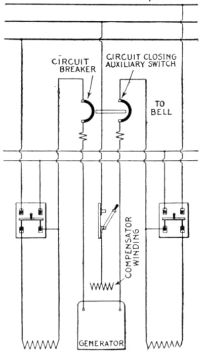
Fig. 2,348.—Diagram showing three wire dynamo protected by double pole double coil overload circuit breaker (or two single pole breakers with interlock) with bell alarm switches. Complete protection is secured as breaker is connected between armature and series field.
Operating conditions sometimes make it advisable for the generator circuit breakers to open only after the auxiliary and feeder circuit breakers have failed to isolate the trouble.
This is accomplished by using direct current series inverse time limit relays to trip the generator circuit breakers.
Instantaneous reverse current relays are used to trip the machine circuit breaker of battery charging sets, rotaries and motor generator sets to prevent their running as a motor on the charging or direct current end. These relays can act only in case of current reversal.
To prevent serious unbalancing of voltages in Edison three-wire systems causing trouble, differential balance relays are used to trip the circuit breakers on a small percentage of unbalancing.