Chapter LI · ALTERNATING CURRENT MOTORS (continued 2)
Reading edition
Ques. For what size motors is the internal resistance method suited?
Ans. Small motors.
Ques. Why is it not desirable for large motors?
Ans. The excessive I2R loss in the resistances, if confined within the armature spider, would produce considerable heating, and on this account it is best placed external to the motor.
Ques. On what class of circuit are internal resistance motors desirable?
Ans. On circuits devoted to lighting service as well as power service, where a high degree of voltage regulation is essential.
The initial rush of current when a squirrel cage motor is thrown on the line is more or less objectionable and there are central stations which allow only resistance type of induction motor to be used on their lines.
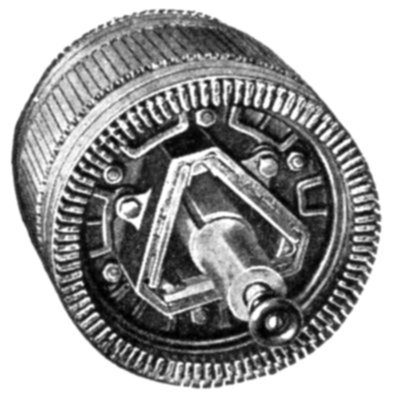
Fig. 1,764.—Western Electric wound armature for internal resistance induction motor. In starting the inductors are short circuited through a resistance which is gradually cut out as the motor comes up to speed.
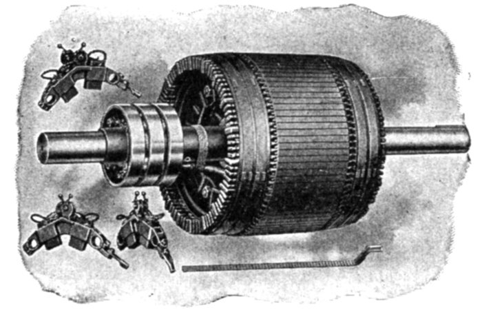
Figs. 1,765 to 1769.—Western Electric wound armature for external resistance, or slip ring induction motor, showing brush rigging, slip rings and bar winding.
External Resistance or Slip Ring Motors.—In large machines, and those which must run at variable speed, such as is required in the operations of cranes, hoists, dredges, etc., it is advisable that the regulating resistances be placed externally to the motor. Motors having this feature are commercially known as slip ring motors, because connections are made between the external resistances and the armature inductors by means of slip rings.
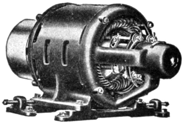
Fig. 1,770.—Richmond slip ring motor.
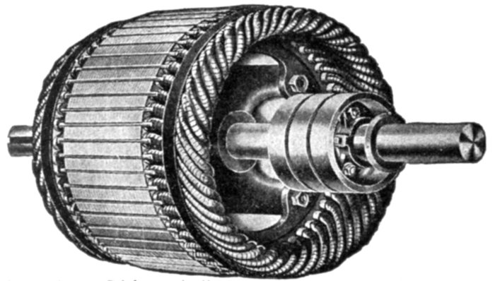
Fig. 1,771.—Richmond slip ring armature as used on motor in fig. 1,770.
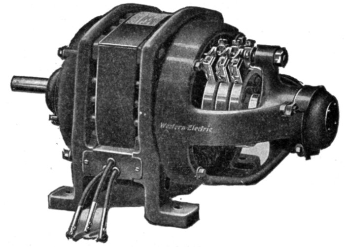
Fig. 1,772.—Western Electric riveted frame slip ring induction motor for variable speed service; adapted either to continuous or intermittent operation.
As with the internal resistance motor the armature winding of a slip ring motor is not short circuited through copper rings in starting, but through a resistance, which in this case is located externally.
Ques. How is the armature winding connected?
Ans. It is connected in Y grouping and the free ends connected to the slip rings, leads going from the brushes to the variable external resistances, these being illustrated in fig. 1,779.
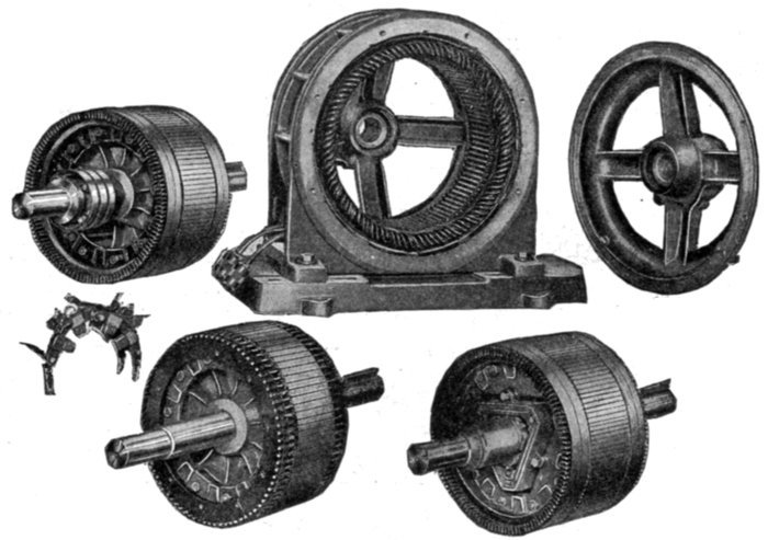
Figs. 1,773 to 1,778.—Sprague skeleton type motor frame with various types of armature. Fig. 1,777, plain squirrel cage armature; fig. 1,778, internal resistance armature; fig. 1,773 slip ring armature. In the construction of the plain squirrel cage armature, fig. 1,777, copper bars are inserted in the slots of the core, and are insulated from the core by enclosing tubes which project about one-half inch beyond the iron at each side. The bars are short circuited at their ends by copper rings. These rings are thin, but of considerable radial depth and are held apart by spacing washers. They have rectangular holes punched near their outward periphery, through which the armature bars pass, and to which they are soldered. The internal resistance armature, fig. 1,778, is provided with a phase winding, starting (internal) resistance, and switch located on the shaft. The starting resistance is designed to give approximately full load torque with full load current at starting. A greater torque than full load torque can be obtained for starting, if required, by cutting out resistance. The resistance consists of cast iron grids enclosed in a triangular cover which is bolted to the end plates holding the armature laminæ together, and is short circuited by sliding laminated spring metal brushes along the inside surface of the grids. The brushes are supported by a metal sleeve sliding on the shaft which is operated by a lever secured to the bearing bracket and located just above the bearing. A rod passing through the end of the shaft operates the short circuiting arrangement in sizes up to about 25 horse power. The external resistance or slip ring armature, fig. 1,773, is similar in construction to fig. 1,778, with the exception that slip rings are provided because of the external location of the resistance. These rings connect the inductor through brushes to a controlling and external resistance, two or more carbon brushes being provided for each ring, as in fig. 1,776.
Single Phase Induction Motors.—The general utility of single phase motors, particularly the smaller sizes, is constantly being enlarged by the growing practice of central stations generating polyphase current, of supplying their lighting service through single phase distribution, and permitting the use of single phase motors of moderate capacity on the lighting circuit.
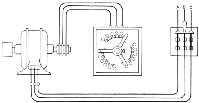
Fig. 1,779.—External resistance or slip ring induction motor connections. The squirrel cage armature winding is not short circuited by copper end rings, but connected in Y grouping and the three free ends connected to three slip rings, leads going from the brushes to three external resistances, arranged as triplex rheostat having three arms rigidly connected as shown, so that the three resistances may be varied simultaneously and in equal amounts.
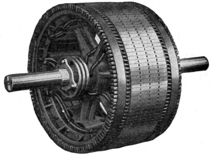
Fig. 1,800.—Allis-Chalmers phase wound external resistance type or slip ring armature construction. The winding is for three phases and the terminals are brought out to three slip rings. The front bracket is slightly modified to make room for these rings on the inside. For starting duty sufficient resistance is supplied to reduce the starting current taken by the motor to 1¼ times the normal full load current. In the running position the resistance is all cut out of the circuit. For speed regulation sufficient resistance is supplied to reduce the speed 50% on normal full load torque.
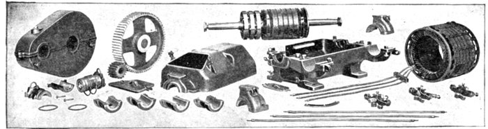
Figs. 1,801 to 1,828.—Disassembled view of Western Electric three phase external resistance or slip ring mill type induction motor. It is adapted to severe working conditions, such as are met with in steel mills, crane and hoist service, etc. Designed for 220 or 440 volt, 25 cycle circuits. The frame is divided horizontally into an upper and a lower steel casting, both of which are bolted together at the corners by four heavy bolts. The lower casting is provided with four feet for bolting the motor to its foundation. The end of the upper frame which covers the slip rings is equipped with malleable iron covers held in place by lock bolts. The field and armature are of the usual construction. One end of the armature winding is protected against mechanical injury by the slip rings which are of heavy construction and of practically the same diameter as the armature, and the other end by a detachable flange of the same diameter as the outside of the winding. The slip rings are mounted on the same spider as the armature, so that the shaft can be removed without disturbing any of the connections. The brushes are equipped with riveted pigtails, and held in brass brush boxes machined to gauge. Heavy coiled clock springs are used to maintain an even pressure of the brushes on the slip rings. The armature leads are brought out through holes in the upper half of the frame, and the field leads are brought through a block, which fits in an opening in the upper edge of the lower half.
The simplicity of single phase systems in comparison with polyphase systems, makes them more desirable for small alternating current plants.
The disadvantage of single phase motors is that they are not self-starting.
A single phase motor consists essentially of an armature and field magnet having a single phase winding and also some phase splitting arrangement for starting.
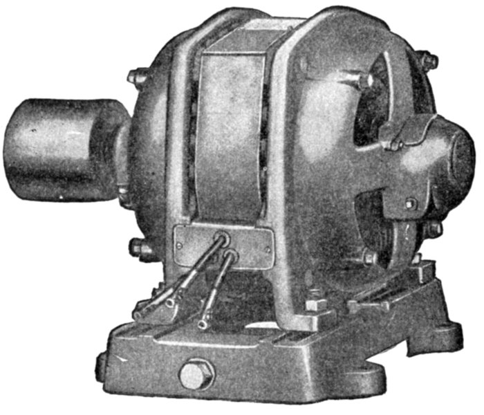
Fig. 1829.—General Electric single phase induction motor. It is suitable for constant speed service where full load torque at starting does not exceed 140 per cent., and in general is adapted to drive all geared and belted machinery requiring constant speed with light or moderate starting torque.
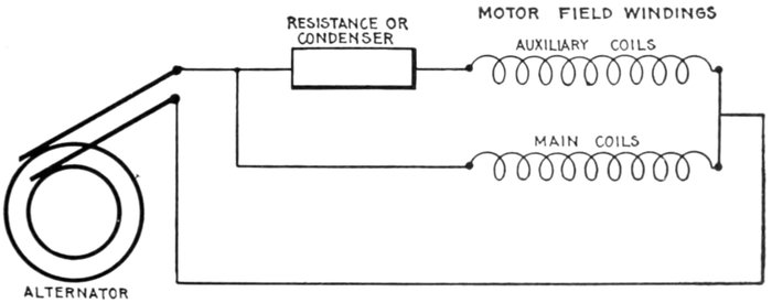
Fig. 1,830.—Simplified diagram showing the principle of phase splitting for starting single phase induction motors. By the use of an auxiliary set of coils connected in parallel with the main coils and having in series a resistance or condenser as shown, the single phase current delivered by the alternator is "split" into two phases, which are employed to produce a rotating field on which the motor is started.
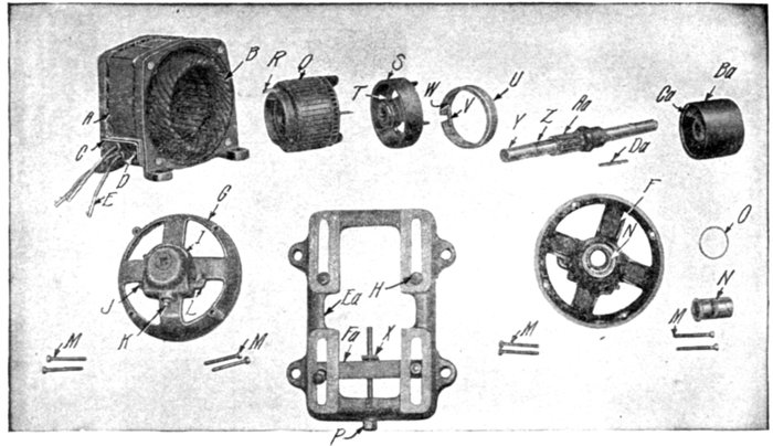
Figs. 1,831 to 1,850.—Parts of Sprague single phase clutch type induction motor. The armature is of the high resistance smooth core squirrel cage type, the core laminæ being assembled upon a steel sleeve. On starting the armature revolves freely around the shaft on roller bearings until it accelerates to about 75% of its rated speed, when a centrifugal clutch engages with an outer shell keyed directly on the shaft, thus throwing on the load. This type of motor is adapted to drive all belted, geared, or direct connected machinery requiring constant speed with moderate starting torque, such as generators, blowers, line shafting in machine shops and factories, drill presses, laundry machinery, baking machinery, and the like. When greater torque is required at the moment of starting type RI motors should be used, or clutch couplings may be installed between the motor and the machine it is to drive. The parts are as follows; A, field frame; B, field coils; C, terminal block; D, terminal block screws; E, connectors; F, bearing head pulley end; G, bearing head opposite pulley end; H, motor clamping bolts; I, oil well cover; J, oil well plug; K, drain plug; L, oil filter; M, cap bolts; N, bearing lining; O, oil ring; P, belt tightener screw; Q, armature core; R, latch; S, driving shell; T, driving shell set screw; U, clutch ring; V, clutch ring spring; W, spring adjusting screw; X, nut for belt tightener screw; Y, shaft; Z, driving shell key; Aa, armature bearing; Ba, pulley; Ca, pulley set screw; Da, pulley key; Ea, sliding base; Fa, yoke.
Ques. Why is a single phase motor not self-starting?
Ans. Because the nature of the field produced by a single phase current is oscillating and not rotating.
Ques. How is a single phase motor started?
Ans. By splitting the phase, a field is set up normal to the axis of the armature, and nearly 90° displaced in phase from the field in that axis. This cross field produces the useful torque.
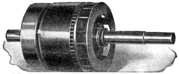
Fig. 1,851.—General Electric high resistance clutch type smooth core squirrel cage armature of single phase induction motor. The core laminæ are slotted near the circumference to retain the bar inductors, which extend beyond the core at either end where they are permanently connected to heavy short circuiting rings.
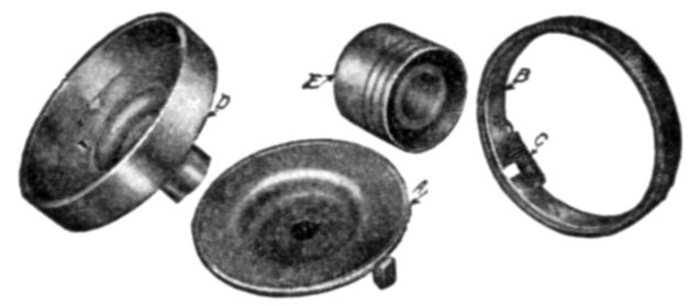
Figs. 1,852 to 1,855.—Parts of General Electric centrifugal clutch pulley as used on clutch type, single phase induction motor. A, clutch; B, friction band; C, adjusting spring; D, outer clutch shell with pulley sleeve; E, solid removable pulley; F, internal mechanism comprising parts A, B, and C; G, outer shell and pulley comprising parts D and E.
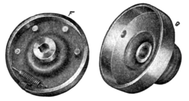
Figs. 1,856 and 1,857.—Partly assembled clutch pulley. F, internal mechanism comprising parts A, B, C, of fig. 1,852. G, outer shell and pulley, comprising parts D and E of fig. 1,852.
Phase Splitting; Production of Rotating Field from Oscillating Field.—As previously stated, an oscillating field, that is, one due to a single phase current, does not furnish any starting torque. It is therefore necessary to provide a rotating field for a single phase induction motor to start on, which, after the motor has come up to speed, may be cut out and the motor will then operate with the oscillating field.
A rotating field may be obtained from single phase current by what is known as splitting the phase.
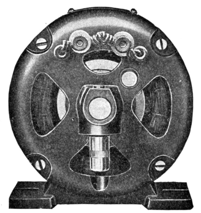
Fig. 1,858.—Switch end view of General Electric drawn shell type fractional horse power single phase motor.
Ques. Describe one method of splitting the phase.
Ans. The field of the motor is provided, in addition to the main single phase winding, with an auxiliary single phase winding, and the two windings are connected in parallel to the single phase supply mains with a resistance or a condenser placed in series with the single phase winding, as shown in diagram fig. 1,830, the two windings being displaced from each other on the armature about 90 magnetic degrees, just as in the ordinary two phase motor.
Ques. What is the construction of the two windings?
Ans. The main coils are of more turns than the auxiliary, being spread over more surface, and are heavier because they are for constant use; whereas the auxiliary coils are used only while starting.
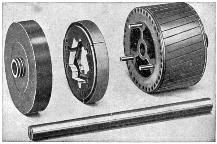
Figs. 1,859 to 1,862.—Detail construction of clutch parts of General Electric drawn shell type fractional horse power single phase motor. The starting switch, which is assembled within the motor frame, consists essentially of three parts: a rotating member mounted on the armature and provided with two spring controlled pivoted levers in contact with an insulated collector ring.
Ques. What are the auxiliary coils sometimes called?
Ans. Starting coils.
Ques. What are "shading" coils?
Ans. Auxiliary coils as placed on fan motors in the manner shown in fig. 1,863.
Ques. How can single phase motors be started without the use of external phase splitting devices?
Ans. Such apparatus may be avoided by having the auxiliary winding of larger self-inductance than the main winding.
Ques. What is the character of the starting torque produced by splitting the phase?
Ans. It does not give strong starting torque.
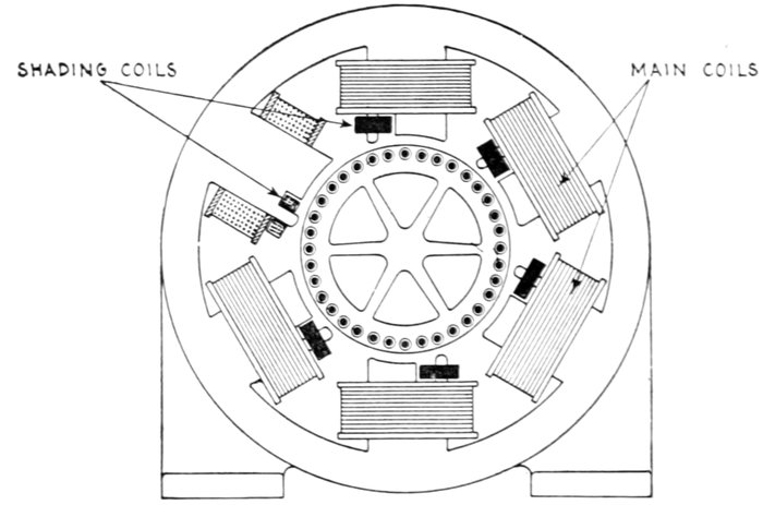
Fig. 1,863.—Single phase fan motor with shading coils for starting. In addition to the main field coils, one tip of each pole piece is surrounded by a short circuited coil of wire or frame of copper, as indicated in the figure. This coil, or copper frame, is called a shading coil and it causes a phase difference between the pulsating flux that emanates from the main portion of each polar projection and the pulsating flux which emanates from the pole tip, thus introducing a two phase action on the armature which is sufficiently pronounced to start the motor.
Ques. How is the plain squirrel cage armature modified to enable the motor to start with a heavier load?
Ans. An automatic clutch is provided which allows the armature to turn free on the shaft until it accelerates almost to running speed.
This type motor is known as the clutch type of single phase induction motor. In operation when the circuit is closed, the armature starts to revolve upon the shaft; when it reaches a premeditated speed, a centrifugal clutch expands and engages the clutch disc, which is fastened to the shaft.
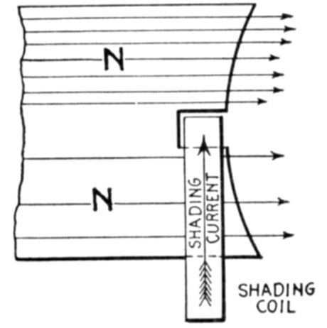
Fig. 1,864.—Diagram showing action of shading coil in alternating current motor. The extremities of these pole pieces are divided into two branches, one of which a copper ring called a shading coil is placed as shown, while the other is left unshaded. The action of the shading coils is as follows: Consider the field poles to be energized by single phase current, and assume the current to be flowing in a direction to make a north pole at the top. Consider the poles to be just at the point of forming. Lines of force will tend to pass downward through the shading coil and the remainder of the pole. Any change of lines within the shading coil generates an e.m.f., which causes to flow through the coil a current of a value depending on the e.m.f. and always in a direction to oppose the change of lines. The field flux is, therefore, partly shifted to the free portion of the pole, while the accumulation of lines through the shading coil is retarded.
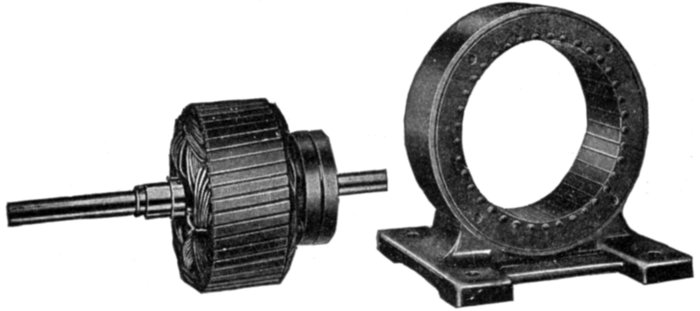
Figs. 1,865 and 1,866.—Fort Wayne split phase factional horse power induction motor with stationary armature. The object of placing the squirrel cage armature winding on the stationary part or frame is to decrease the radial depth of the latter more than would be possible with the usual arrangement where the armature forms the rotating part. The small radial depth of the stationary armature makes possible a revolving field of maximum diameter giving in turn an exceptionally large air gap area, which reduces the magnetizing current, hence improves the power factor of the motor.
Ques. Explain in detail the action of the clutch type of motor in starting.
Ans. It can start a load which requires much more than full load torque at starting, because the motor being nearly up to full speed, has available not only its maximum overload capacity, but also the momentum of the armature to overcome the inertia of the driven apparatus. In this it is assisted by a certain amount of slippage in the clutch, which is the case when the armature speed is pulled down to such a point as to reduce the grip of the centrifugal clutch.
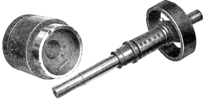
Figs. 1,867 and 1,868.—General Electric disassembled clutch as used on clutch type, single phase (KS) induction motor. In starting, the armature revolves freely on the shaft until approximately 75 per cent. of normal rated speed is reached. The load is then picked up by the automatic action of a centrifugal clutch, which rigidly engages an outer shell, keyed directly to the shaft. The brass friction band of the clutch is permanently keyed to the pulley end of the armature.
Commutator Motors.—Machines of this class are similar in general construction to direct current motors. They have a closed coil winding, which is connected to a commutator.
There are several types of commutator motor, namely:
1. Series;
2. Shunt;
3. Compensated;
4. Repulsion.
Since, as stated, commutator motors are similar to direct current motors, the question may be asked: Is it possible to run a direct current motor with alternating current? If the mains leading to a direct current motor be reversed, the direction or rotation remains the same, because the currents through both the field magnets and armature are reversed. It must follow then that an alternating current applied to a direct current motor would cause rotation of the armature.
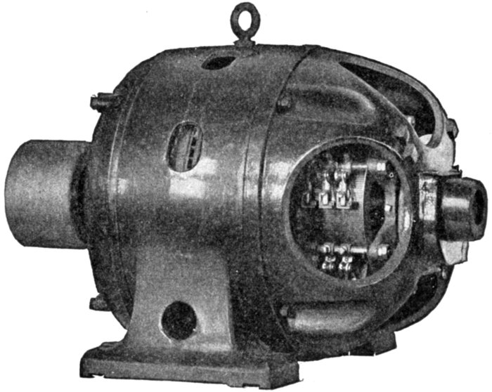
Fig. 1,869.—Wagner single phase variable speed commutator motor. The commutator is of the regular horizontal type and the brushes remain in contact all the time. As the torque of alternating motors varies directly as the square of the applied pressure, wide speed variation may be obtained by varying the voltage applied at the motor terminals.
Action of Closed Coil Rotating in Alternating Field.—When a closed coil rotates in an alternating field, there are several different pressures set up and in order to carefully distinguish between them, they may be called:
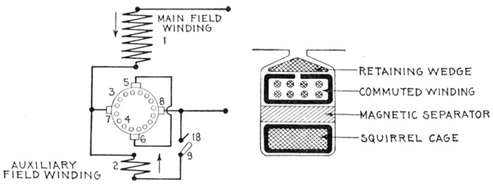
Figs. 1,870 and 1,871.—Diagrams illustrating construction and operation of Wagner "unity power factor" single phase motor. In the field construction, fig. 1,870, two windings are used. The main winding 1 produces the initial field magnetization as heretofore; the auxiliary winding 2 controls the power factor or "compensates" the motor. The main structural departure is in the armature, the construction of which is more clearly indicated in fig. 1,871. Here again two windings are employed. The main or principal winding 4 is of the usual well known squirrel cage type and occupies the bottom of the armature slots. The second or auxiliary winding 3 is of the usual commuted type, is connected to a standard form of horizontal commutator and occupies the upper portion of the armature slots. Between the two is placed a magnetic separator in the form of a rolled steel bar. Two sets of brushes are provided, as indicated in the diagram of connections shown in fig. 1,870. The main pair of brushes 5-6 is placed in the axis of the main field winding 1 and is short circuited. The auxiliary pair of brushes 7-8 is placed at right angles to the axis of the main field winding and is connected in series with it at starting. The auxiliary field winding 2 is permanently connected to one auxiliary brush 7, and is adapted to be connected to the other auxiliary brush 8 by means of the switch 9. The purpose of the peculiar armature construction illustrated in fig. 1,871 and of the brush arrangement and connections shown in fig. 1,870 is to accentuate, at starting, the effect of the squirrel cage along the axis 5-6 of the main field winding 1, while suppressing it as far as possible along the axis 7-8 at right angles to main winding. The magnetic separator placed above the squirrel cage winding 4 tends to suppress the effect of that winding along all axes, by making it less responsive to outside inductive effects. But the influence of the separator is nullified along the axis of the main field winding by the presence of the short circuited brushes 5-6, while no means are provided for nullifying its effects along the axis at right angles to that of the main field winding. Thus the main field winding 1 will be able to induce heavy currents in both armature windings because of the short circuited brushes in the axis 5-6, and in spite of the magnetic separator; while the armature winding 3, connected in series with 1, will not be able to produce heavy currents in the squirrel cage winding 4 along the axis 7-8 because of the magnetic separator between 3 and 4, which shunts or side tracks the inducing magnetic flux. In operation, at starting, switch 9 of fig. 1,870 is open, the commuted winding 3 along the axis 7-8 being connected in series with the main field winding 1 and across the mains. The winding 1 induces a large current in the armature windings 3 and 4 along the axis 5-6, and the winding 3 produces a large flux along the axis 7-8. The armature currents in the main axis co-acting with the flux threading the armature along the auxiliary axis yield the greater part of the starting torque. As the motor speeds up, the squirrel cage gradually assumes those functions which it performs in the ordinary single phase, squirrel cage motor, developing a magnetic field of its own along the axis 7-8 and a correspondingly powerful torque, which increases very rapidly as synchronism is approached, but falls suddenly to zero at or near actual synchronism. It is known that the magnetizing currents circulating in the bars of the squirrel cage of a single phase motor have, at synchronism, double the frequency of the stator currents; the fluxes they produce must therefore also be of double frequency. Now, the magnetic separator is made of solid steel, and, while this separator forms a sufficiently effective shunt for the fluxes of line frequency induced from the field, it is quite ineffective as a shunt for the double frequency fluxes produced by the armature. With respect to the squirrel cage, the effect of this magnetic separator diminishes with increasing speed, and at synchronism the machine operates practically in the same manner as if the magnetic separator did not exist.
1. The transformer pressure;
2. The generated pressure;
3. The self-induction pressure.
These pressures may be defined as follows:
The transformer pressure is that pressure induced in the armature by the alternating flux from the field magnets.
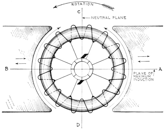
Fig. 1,872.—Diagram of ring armature in alternating field illustrating the principles of commutator motors.
For instance, assuming in fig. 1,872 the armature to be at rest, as the alternating current which energizes the magnets rises and falls in value, the variations of flux which threads through the coils of the ring winding, induce pressure in them in just the same way that pressure is induced in the secondary of a transformer.
A ring winding is used for simplicity; the same conditions obtain in a drum winding.
The generated pressure is that pressure induced in the armature by the cutting of the flux when the armature rotates.
The self-induction pressure is that pressure induced in both the field and armature by self-induction.
Nature of the Generated Pressure.—In fig. 1,872, the generated pressure induced by the rotation of the armature is minimum at the neutral plane C D and maximum at A B. It tends to cause current to flow up each half of the armature from D to C, producing poles at these points.
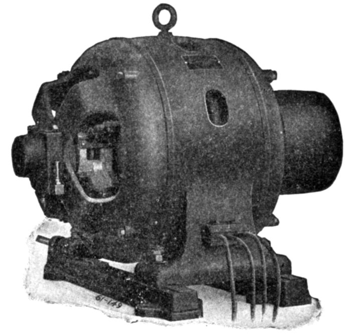
Fig. 1,873.—Wagner single phase repulsion induction commutator motor. Its working principle is repulsion start and induction operation. Starting with the machine at rest, brushes in pairs cross connected through a low resistance conductor, bear upon the commutator, temporarily short circuiting the armature winding then developing a strong starting torque on the repulsion principle. On attaining full load speed the individual segments of the commutator are all positively connected together by the operation of an automatic centrifugal governor, thereby transforming the armature winding to the squirrel cage form, the motor then continuing as an induction motor. The governor at the same time removes the brushes from contact with the commutator to save wear. If the power service should fail for any reason, the motor returns to the starting condition, and picks up its load when the power comes on again without attention of the operator.
Nature of the Transformer Pressure.—This is caused by variations of the flux passing through each coil of the armature winding. Evidently this variation is least at the plane A B because at this point the coils are inclined very acutely to the flux, and greatest at the plane C D where the coils are perpendicular to the flux. Accordingly, the transformer pressure induced in the armature winding is least at A B and greatest at C D.
The transformer pressure acts in the same direction as the generated pressure as indicated by the long arrows and gives rise to what may be called local armature currents.
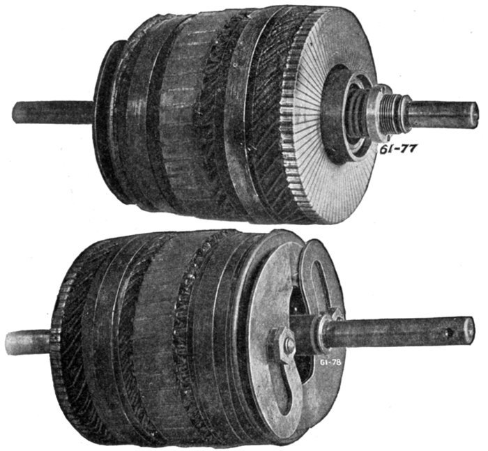
Figs. 1,874 and 1,875.—Armature of Wagner single phase repulsion-induction commutator motor as seen from the commutator and rear ends, showing the vertical commutator and type of governor employed on the smaller sizes. The operation is explained in fig. 1,873.
Nature of the Self-induction Pressure.—The self-induction pressure, being opposite in direction to the impressed pressure, it must be evident that in the operation of an alternating current commutator motor, the impressed pressure must overcome not only the generated
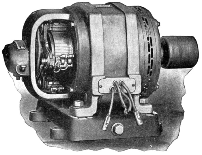
Fig. 1,876.—General Electric single phase compensated repulsion motor. The frame is of the riveted form and the field winding consists of distributed concentric coils, each being separately insulated and taped up to each core slot. The compensating winding (depending usually on the size of frame), forms either the center portion of the main winding or a separate winding concentric therewith. The polar groupings are arranged for a frequency of 25 and 60. There are four terminal leads permitting interchangeability of operation on 110 or 220 volt circuits. By connecting adjacent pairs of these terminals in multiple, motors of this type are made adaptable for 110 volt service; for double this pressure the four leading in wires are connected in series. The motor will operate satisfactorily where the arithmetical sum of voltage and frequency variation does not exceed 10 per cent.; that is, the voltage may be 10 per cent. high if the frequency remain at normal, or the frequency may be 10 per cent. high assuming no variation in voltage. A decrease of 5 per cent. in frequency accompanied by a similar increase in voltage is permissible or, as above stated, any similar combination whose arithmetical sum is within 10 per cent. of normal. The armature winding is of the series drum type connected to a commutator carrying two sets of brushes, each set being displaced electrically from the other by 90 degrees. The first set, known as the energy brushes, is permanently short circuited and disposed at an angle to the lines of field or primary magnetization, as in an ordinary repulsion motor. The second set, or compensating brushes, is connected to a small portion of the primary winding included in the field circuit, so as to impress upon the armature an electromotive force, which serves both to raise the power factor and at the same time maintain approximately synchronous speed at all loads. The armature laminations are built up on a cast iron sleeve having the same inside bore as the commutator. In case the shaft become damaged or worn, it can be readily pressed out and replaced without disturbing the commutator or windings. The motor is connected to run counter clockwise. Clockwise rotation is obtained by interchanging the leads to the compensating brushes and slightly shifting the brush holder yoke. This type motor may be thrown on the line without the use of a rheostat, and is suitable for operating refrigerating machines, air compressors, house pumps or similar apparatus where a float switch or pressure regulator is used to close or open the supply circuit.
pressure but also the self-induction pressure. Hence, as compared to an equivalent direct current motor, the applied voltage must be greater than in the direct current machine, to produce an equal current.
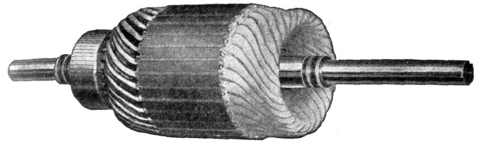
Fig. 1,877.—Armature of General Electric single phase compensated repulsion motor, assembled ready for dip and banding.
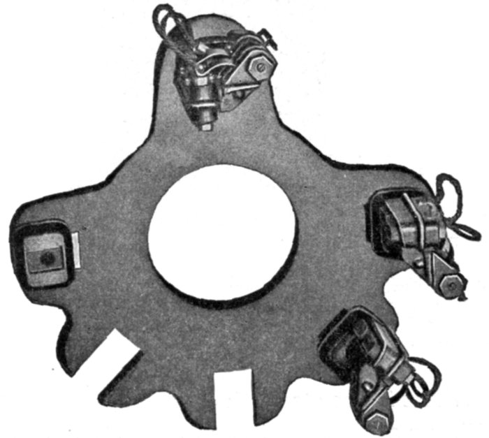
Fig. 1,878.—Cast brush rigging of General Electric single phase compensated repulsion motor as used for the 3 and 5 horse power motors.
The Local Armature Currents.—These currents produced by the transformer pressure occur in those coils undergoing commutation. They are large, because the maximum transformer action occurs in them, that is, in the coils short circuited by the brushes.
Ques. Why do the local armature currents cause sparking?
Ans. Because of the sudden interruption of the large volume of current, and also because the flux set up by the local currents being in opposition to the field flux, tends to weaken the field just when and where its greatest strength is required for commutation.
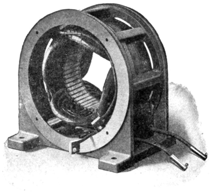
Fig. 1,879.—Field of Sprague single phase compensated repulsion motor. The frame is of the skeleton form which exposes the core, giving effective heat radiation. The single phase field winding is of the distributed concentric type. To facilitate connection to circuits of either 110 or 220 volts, four plainly tagged leads are brought out to the back of the removable terminal board.
Ques. What is the strength of the local current?
Ans. They may be from 5 to 15 times the strength of the normal armature current.
Ques. Upon what does the local armature current depend?
Ans. Upon the number of turns of the short circuited coils, their resistance, and the frequency.
Ques. How can the local currents be reduced to avoid heavy sparking?
Ans. 1. By reducing the number of turns of the short circuited coils, that is, providing a greater number of commutator bars; 2, reducing the frequency; and 3, increasing the resistance of the short circuited coil circuit: a, by means of high resistance connectors; or b, by using brushes of higher resistance.
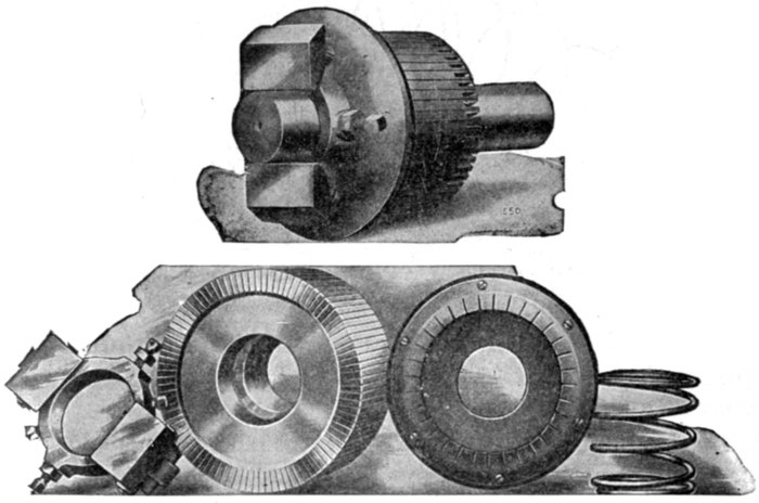
Figs. 1,880 to 1,884.—Assembly and disassembled view of short circuiting device as used on Bell single phase repulsion induction motor. The armature, which is wound in a similar manner to those used in direct current motors, has a commutator, and brushes, which being short circuited on themselves, allow great starting torque, with small starting current. The motor starts by the repulsion principle, and on reaching nearly full speed, a centrifugal governor pushes the copper ring against the commutator segments, thereby short circuiting them, and the motor then operates on the induction principle.
Ques. What are high resistance connectors?
Ans. The connectors between the armature winding and the commutator bars, as shown in fig. 1,885.
Ques. Does the added resistance of preventive leads, or high resistance brushes, materially reduce the efficiency of the machine?
Ans. Not to any great extent, because it is very small in comparison with the resistance of the whole armature winding.
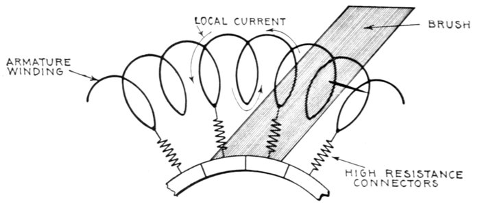
Fig. 1,885.—Section of ring armature of commutator motor showing local current set up by transformer action of the alternating flux.
Ques. What is the objection to reducing the number of turns of the short circuited coils to diminish the tendency to sparking?
Ans. The cost of the additional number of commutator bars and connectors as well as the added mechanism.
Ques. What effect has the inductance of the field and armature on the power factor?
Ans. It produces phase difference between the current and impressed pressure resulting in a low power factor.
Ques. What is the effect of this low power factor?
Ans. The regulation and efficiency of the system is impaired.
The frequency, the field flux and the number of turns in the winding have influence on the power factor.
Ques. How does the frequency affect the power factor?
Ans. Lowering the frequency tends to improve the power factor.
The use of very low frequencies has the disadvantage of departing from standard frequencies, and the probability that the greater cost of transformers and alternators would offset the gain.
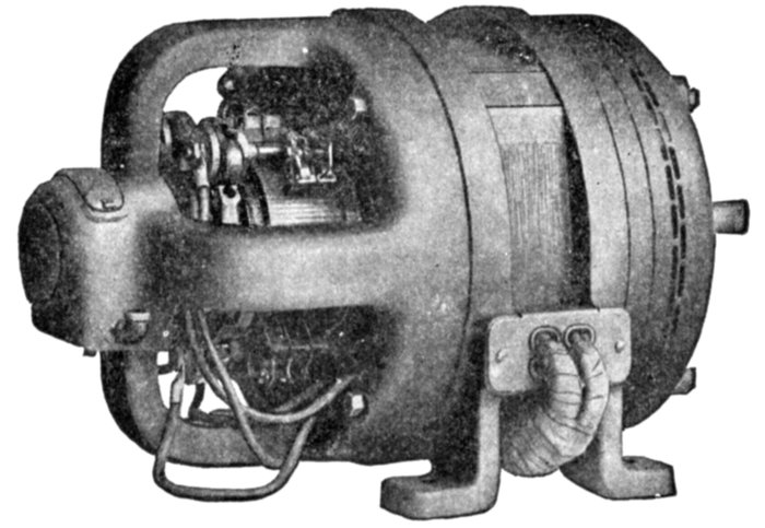
Fig. 1,886.—General Electric 5 H.P., 6 pole adjustable speed single phase compensated repulsion motor. This type is suitable for service requirements demanding the use of a motor whose speed can be adjusted over a considerable range, this speed at a fixed controller setting remaining practically unaffected by any load within the motor's rated capacity. With the controller on the high speed points, the motor possesses an inherent speed regulation between no load and full load of approximately 6 per cent. At the low speed points, under similar load conditions, the speed variation will be approximately 20 per cent. To secure adjustable speed control, the armature circuits employ transformers, whose primaries are excited by the line circuit. The secondaries of these transformers are divided into two sections; the first or "regulating" circuit is placed across the energy brushes; the other section, since it is connected in series with the compensating winding, maintains the high power factor and speed regulation obtained in the constant speed type. The speed range is 2:1, approximately one-half of this range being below and one-half above synchronous speed.
Series Motors.—This class of commutator motor is about the simplest of the several types belonging to this division. In general design the series motor is identical with the series direct current motor, but all the iron of the magnetic circuit must be laminated and a neutralizing winding is often employed.
It will be readily understood that the torque is produced in the same way as in the direct current machine, when it is remembered that the direction of rotation of the direct current series motor is independent of the direction of the voltage applied.
At any moment the torque will be proportional to the product of the current and the flux which it is at that moment producing in the magnetic system, and the average torque will be the product of the average current and the average flux it produces, so that if the iron parts be unsaturated, as they must be if the iron losses are not to be too high, the torque will be proportional simply to the square of the current, there being no question of power factor entering into the consideration.
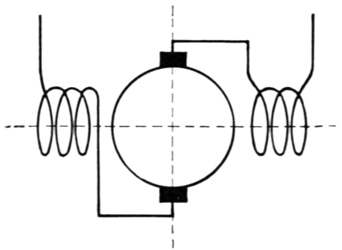
Fig. 1,887.—Diagram of single phase series commutator motor. It is practically the same as the series direct current motor, with the exception that all the metal of the magnetic circuit must be laminated.
Ques. What are the characteristics of the series motor?
Ans. They are similar to the direct current series motor, the torque being a maximum at starting and decreasing as the speed increases.
Ques. For what service is the series motor especially suited?
Ans. On account of its powerful starting torque it is particularly desirable for traction service.
Neutralized Series Motor.—A chief defect of the series motor is the excessive self-induction of the armature, hence in almost every modern single phase series motor a neutralizing coil is employed to diminish the armature self-induction.
The neutralizing coil is wound upon the frame 90 magnetic degrees or half a pole pitch from the field winding and arranged to carry a current equal in magnetic pressure and opposite in phase to the current in the armature.
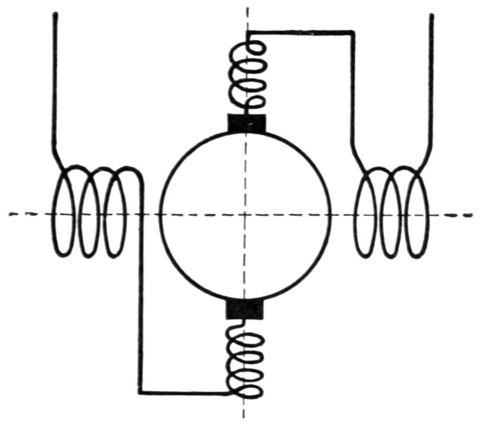
Fig. 1,888.—Diagram of neutralized series motor; conductive method. In the simple series motor, there will be a distortion of the flux as in the direct current motor. As the distorting magnetic pressure is in phase with that of the magnets, the distortion of the flux will be a fixed effect. If the poles be definite as in direct current machines, this distortion may not seriously affect the running of the motor, but with a magnetizing system like that universally adopted in induction motors the flux will be shifted as a whole in the direction of the distortion, which will produce the same effect as if in the former case the brushes had been shifted forward, whereas for good commutation they should have been shifted backward. As in direct current machines, this distortion is undesirable since it is not conducive to sparkless working, and also reduces to a more or less extent the torque exerted by the motor. The simplest remedy is to provide neutralizing coils displaced 90 magnetic degrees to the main field coils as shown. The neutralizing current is obtained by the method of connecting the neutralizing coils in series in the main circuit.
The current through the neutralizing winding may be obtained, either
1. Conductively; or
2. Inductively.
In the conductive method, fig. 1,888, the winding is connected in series as shown.
In the inductive method, fig. 1,889, the winding is short circuited upon itself and the current obtained inductively, the neutralizing winding being virtually the secondary of a transformer, of which the armature is the primary.
Ques. When is the conductive method to be preferred?
Ans. When the motor is to be used on mixed circuits.
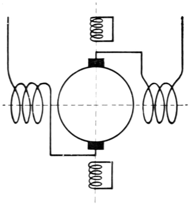
Fig. 1,889.—Diagram of neutralized series motor; inductive method. Although the conductive method of neutralization is employed in nearly all machines, it is possible merely to short circuit the neutralizing winding upon itself, instead of connecting it in series with the armature circuit. In this case the flux due to the armature circuit cannot be eliminated altogether, as sufficient flux must always remain to produce enough pressure to balance that due to the residual impedance of the neutralizing coil. It would be a mistake to infer, however, that on this account this method of neutralization is less effective than the conductive one, since the residual flux simply serves to transfer to the armature circuit a drop in pressure precisely equivalent to that due to the resistance and local self-induction of the neutralizing coil in the conductive method.
Shunt Motors.—The simple shunt motor has inherently many properties which render it unsuitable for practical use, and accordingly is of little importance. Owing to the many turns of the field winding there is large inductance in the shunt field circuit.
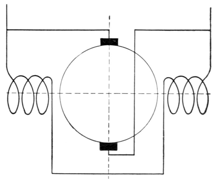
Fig. 1,890.—Diagram of simple shunt commutator motor. Owing to its many inherent defects it is of little importance.
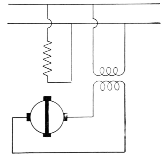
Fig. 1,891.—Compensated shunt induction single phase motor. The transformer shown in the arrangement is capable of being replaced by a coil placed on the frame having the same axis as the field winding, so that the flux produced by the field winding induces in the coil a pressure in phase with the supply pressure. Such a coil will now be at right angles to the circuit to which it is connected. In a similar manner a coil at right angles to the armature circuit, that is, the circuit parallel to the stator axis, if connected in series with that circuit, will also serve to compensate the motor.
Fig. 1,891.—Compensated shunt induction single phase motor. The transformer shown in the arrangement is capable of being replaced by a coil placed on the frame having the same axis as the field winding, so that the flux produced by the field winding induces in the coil a pressure in phase with the supply pressure. Such a coil will now be at right angles to the circuit to which it is connected. In a similar manner a coil at right angles to the armature circuit, that is, the circuit parallel to the stator axis, if connected in series with that circuit, will also serve to compensate the motor.
The inductance of the armature is small as compared with that of the field; accordingly, the two currents differ considerably in phase.
The phase difference between the field and armature currents and the corresponding relation between the respective fluxes results in a weak torque.
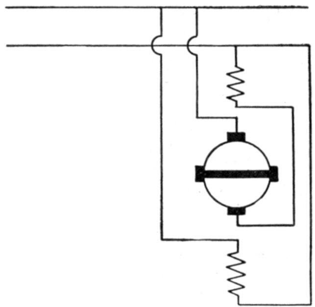
Fig. 1,892.—Fynn's shunt conductive single phase motor. In order to supply along the stator axis a constant field, suitable for producing the cross flux to which the torque is due by its action on the circuit perpendicular to the stator axis, the "armature circuit," as it may be called, has a neutralizing coil in series with it, so that the armature circuit and neutralizing coil together produce no flux. In addition to this, there is a magnetizing coil along the same axis, which is connected across the mains and so produces the same flux as the primary coil in a shunt induction machine. Fynn has proposed a number of methods of varying the speed and compensating this machine. It is, however, complicated in itself, and is only suited for very low voltages, so that on ordinary circuits it would need a separate transformer.
It is necessary to use laminated construction in the field circuit to avoid eddy currents, which otherwise would be excessive. Fig. 1,890 is a diagram of a simple shunt commutator motor.
Repulsion Motors.—In the course of his observations on the effects of alternating currents, in 1886-7, Elihu Thomson observed that a copper ring placed in an alternating magnetic field tends either to move out of the field, that is, it is repelled by the field (hence the name repulsion motor), or to return so as to set itself edgeways to the magnetic lines.
The explanation of the repulsion phenomenon is as follows:
When a closed coil is suspended in an alternating field so that lines of force pass through it, as in fig. 1,893, an alternating pressure will be induced in the coil which will be 90° later in phase than the inducing flux, and since every coil contains some inductance the resulting current will lag more or less with respect to the pressure induced in the coil.
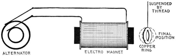
Fig. 1,893.—Effect of alternating field on copper ring. If a copper ring be suspended in an alternating field so that the plane of the ring is oblique to the lines of force, it will turn until its plane is parallel to the lines of force, that is, to the position in which it does not encircle any lines of force. The turning moment acting upon the ring is proportional to the current in it, to the strength of the field, and to the cosine of the angle ß. Hence it is proportional to the product sin ß cos ß. The tendency to turn is zero both at 0° and at 90°; in the former case because there is no current, in the latter because the current has no leverage. It is a maximum when ß = 45°. Even in this position there would be no torque if there were no lag of the currents in the ring, for the phase of the induced pressure is in quadrature with the phase state of the field. When the field is of maximum strength there is no pressure, and when the pressure reaches its maximum there is no field. If there be self-induction in the ring causing the current to lag, there will be a net turning moment tending to diminish ß. The largest torque will be obtained when the lag of the current in the ring is 45°.
The cosine of this phase relation becomes a negative quantity which means that the coil is repelled by the field.
It is only when the ring is in an oblique position that it tends to turn. If it be placed with its plane directly at right angles to the direction of the magnetic lines, it will not turn; if ever so little displaced to the right or left, it will turn until its plane is parallel to the lines.
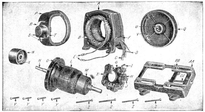
Figs. 1,894 to 1,908.—Parts of General Electric single phase compensated repulsion motor. The field frame employs the riveted form of construction, so that the ends of the laminations are exposed directly to the air, insuring low operating temperatures and high overload capacity. The field winding consists of a main winding of the distributed concentric type and a compensating winding. The series type of winding is employed, and the completed rotor is treated with a special insulating compound, which renders the coils moisture proof under ordinary conditions. On motors of more than 2 horse power capacity a ventilating fan is attached to the rotor which provides a continuous supply of cool air while the motor is in operation. Two types of brush holder yoke are used. The smaller motors use a moulded yoke of insulting compound, reinforced by a cast iron L section ring embedded in the moulded structure. Cast iron yokes are used on larger motors. The brushes are of carbon with copper pigtails, which carry all the current. The brushes in this machine remain permanently in contact with the commutator. The parts are: A, field; B, field winding; C, line terminal; D, tube terminal; E, compensating terminal; F, terminal board; G, brush yoke; H, brush holder; I, carbon brush; J, brush stud; K, short circuit connection; L, armature; M, commutator, N, shaft; O, fan; P, commutator end shield; Q, pulley end shield; R, oil well cover; S, oil plugs; T, oil gauge; U, bearing lining; V, oil ring; W, pulley; X, pulley set screw; Y, commutator end shield holding bolts; Z, pulley end shield holding bolts; AA, base; BB, float bolts; CC, belt tightener screw.
The production of torque may be explained by saying that the current induced in the ring produces a cross field which being out of phase with, and inclined to the field impressed by the primary alternating current, causes a rotary field, and this in turn, reacting on the conductor, a turning moment results.
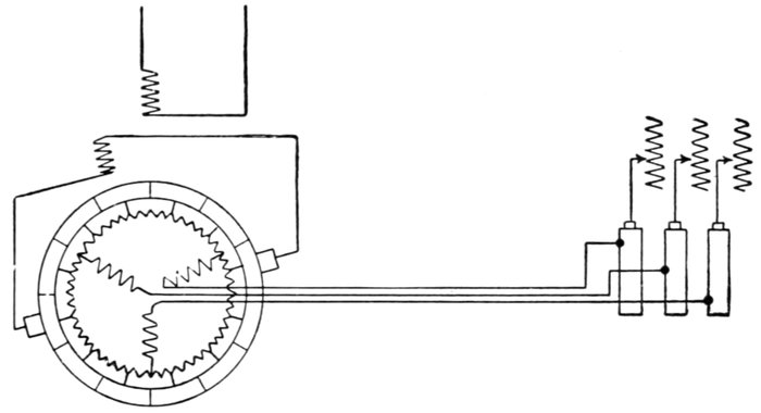
Fig. 1,909.—Fynn's compensated shunt induction motor. This is a combination of the compensated shunt induction motor with the ordinary squirrel cage form. In one form, in addition to the ordinary drum winding on the armature, there is another three phase winding into the "star," of which the drum winding is connected. This second winding is connected to three slip rings which are short circuited when the machine is up to speed. Upon the commutator are placed a pair of brushes connected to an auxiliary winding placed on the frame in such a position that the flux from the primary coil induces in it a pressure of suitable phase to produce compensation. The same pair of brushes is also used for starting.
Elihu Thompson took an ordinary direct current armature, placed it in an alternating field, and having short circuited the brushes, placed them in an oblique position with respect to the direction of the field. The effect was to cause the armature to rotate with a considerable torque.
The inductors of the armature acted just as an obliquely placed ring, but with this difference, that the obliquity was continuously preserved by the brushes and commutator, notwithstanding that the armature turned, and thus the rotation was continuous. This tendency of a conductor to turn from an oblique position was thus utilized by him to get over the difficulty of starting a single phase motor. With this object in view he then constructed motors in which the use of commutator and brushes was restricted to the work of merely starting the armature, which when so started was then entirely short circuited on itself, though disconnected from the rest of the circuit, the operation then being solely on the induction principle.
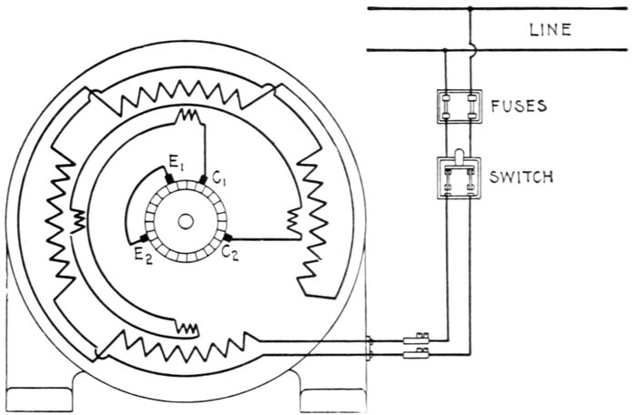
Fig. 1,910.—Diagram of connection of Sprague single phase compensated repulsion motor. To reverse direction of rotation interchange leads C1 and C2 and slightly shift the brush holder yoke. Brushes E1 and E2 are permanently short circuited. This diagram of connections applies also to fig. 1,911.
Ques. What difficulty was experienced with Thomson's motor?
Ans. Since an open coil armature was used, the torque developed was due to only one coil at a time, which involved a necessarily high current in the short circuited coil resulting in heavy sparking.
Ques. How was this remedied?
Ans. By the use of closed coil armatures in later construction.
Ques. Did this effectually stop sparking?
Ans. No.
Ques. What other means is employed in modern designs to reduce sparking?
Ans. Compensation and the use of a distributed field winding, high resistance connectors, high resistance brushes, etc.
Ques. What are the names of the two classes of repulsion motor?
Ans. The simple and the compensated types.
Ques. Describe a simple repulsion motor.
Ans. It consists essentially of an armature, commutator and field magnets. The armature is wound exactly like a direct current armature, and the windings are connected to a commutator. The carbon brushes which rest on this commutator are not connected to the outside line, however, but are all connected together through heavy short circuiting connectors. The brushes are placed about 60° or 70° from the neutral axis. The field is wound exactly like that of the usual induction motor.
Ques. What is the action of this type of motor?
Ans. If nothing be done to prevent, the motor will increase in speed at no load until the armature bursts, just as it will in a series direct current motor.
Ques. What provision is made to avoid this danger?
Ans. A governor is usually mounted on the armature which short circuits the windings, after the motor has been started. The motor then runs as a squirrel cage induction motor. As a rule the brushes are lifted off the commutator when the armature is short circuited, so as to prolong their life.
This is a very successful motor, but it is of course more costly than the simple squirrel cage motor used on two and three-phase circuits.
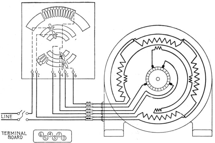
Fig. 1,911.—Diagram of connections of Sprague variable speed single phase compensated repulsion motor and controller. The controller is designed to give speed reduction and speed increase as resistance or reactance is inserted in the energy and compensating circuits. With the exception of the leads brought out from these circuits, the constant speed and variable speed motors are identical. The standard controller gives approximately 2:1 speed variation.
Ques. What name may appropriately be applied to the motor?
Ans. It may be called the repulsion induction motor, because it is constructed for repulsion start and induction running.
Ques. Describe a compensated repulsion motor.
Ans. In its simplest form it consists of a simple repulsion motor in which there are two independent sets of brushes, one set being short circuited, while the other set is in series with the field magnet winding, as in the series alternating current motor.
Ques. What names are given to the two sets of brushes on a compensated repulsion motor?
Ans. The energy or main short circuiting brushes, and the compensating brushes.
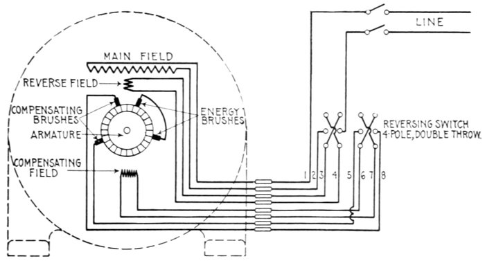
Fig. 1,912.—Diagram of connections of Sprague reversing type of single phase compensated repulsion motor. As shown, there is a special reverse field winding having terminals for connection to a four pole double throw switch.
Ques. What is the behavior of the armature of a compensated repulsion motor at starting?
Ans. It possesses at starting most of the apparent reactance of the motor, and the effect of speed is to decrease such apparent reactance, the latter becoming zero at either positive or negative synchronism, and negative at higher speeds in either direction.
Ques. What is the nature of the field circuit of the compensated repulsion motor at starting?
Ans. At starting it is practically non-inductive, the effect of speed being to introduce a spurious resistance which increases directly with the speed, and becomes negative when the speed is reversed.
Ques. For what use is the compensated repulsion motor especially adapted?
Ans. For light railroad service.
Ques. When employed thus what is the method of control?
Ans. A series transformer is used in the field circuit.
Ques. What frequencies are employed with this motor?
Ans. 25 to 60, the preferred frequency being 40.
Ques. To what important use is the repulsion principle put?
Ans. It is sometimes employed for starting on single phase induction motors.
In this method, after bringing the motor up to speed, the winding is then short circuited upon itself, and the motor then operates on the induction principle.
Ques. What name is given to this type of motor?
Ans. It is called the repulsion induction motor.
Power Factor of Induction Motors.—In the case of a direct current motor, the energy supplied is found by multiplying the current strength by the voltage, but in all induction motors the effect of self-induction causes the current to lag behind the pressure, thereby increasing the amount of current taken by the motor. Accordingly, as the increased current is not utilized by the motor in developing power, the value obtained by multiplying the current by the voltage represents an apparent energy which is greater than the real energy supplied to the motor.
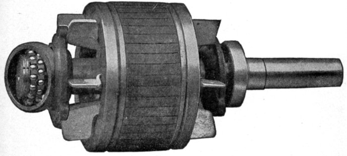
Fig. 1,913.—Fairbanks-Morse squirrel cage armature, showing ball bearings.
It is evident, that if it were possible to eliminate the lag entirely, the real and apparent watts would be equal, and the power factor would be unity.
The importance of power factor and its effect upon both alternator capacity and voltage regulation is deserving of the most careful consideration with all electrical apparatus, in which an inherent phase difference exists between the pressure and the current, as for instance in static transformers and induction motors.
While the belief is current that any decrease in power factor from unity value does not demand any increase of mechanical output, this is not true, since all internal alternator and line losses manifest themselves as heat, the wasted energy to produce this heat being supplied by the prime mover.
Apart from the poor voltage regulation of alternating current generators requiring abnormal field excitation to compensate for low power factor, some of the station's rated output is rendered unavailable and consequently produces no revenue. The poor steam economy of underloaded engines is also a serious source of fuel wastage.
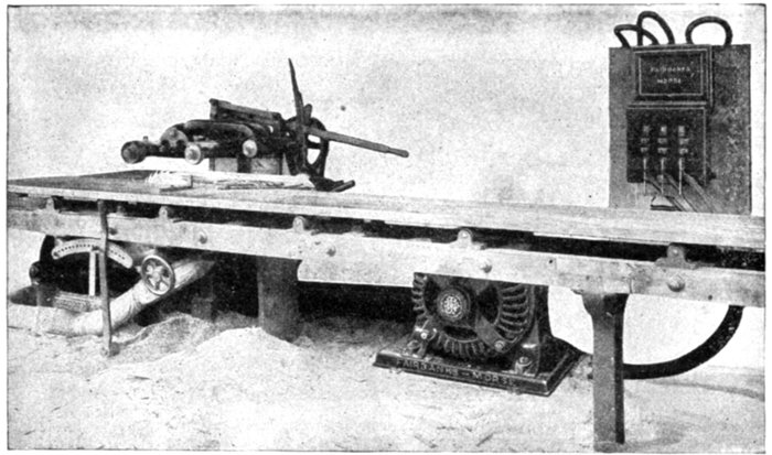
Fig. 1,914.—Fairbanks-Morse 20 horse power squirrel cage induction motor connected to a 20 inch self-feed rip and chamfering saw. The absence of commutator and brushes on the squirrel cage armature eliminates sparking and therefore renders this type of motor particularly adapted for use in places where sparking would be dangerous, such as in wood working plants, textile mills, etc.
Careful investigations have shown that the power factor of industrial plants using induction motor drive with units of various sizes will average between 60 and 80 per cent. With plants supplying current to underloaded motors having inherently high lagging current values, a combined factor as low as 50 per cent. may be expected. Since standard alternators are seldom designed to carry their rated kilowatt load at less than 80 per cent. power factor, the net available output is, therefore, considerably increased.
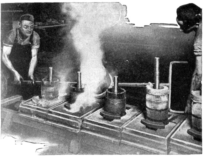
Fig. 1,915.—Method of casting end rings on squirrel cage armatures of Fairbanks-Morse induction motors. The metal being fused to the bars at a temperature in excess of 1,832 degrees Fahr., it is readily seen that the destructive effect of any subsequent heating is eliminated. While giving the most intimate contact at the joints, a multiplicity of joints is avoided as well as solder.
Speed and Torque of Motors.—The speed of an induction motor depends chiefly on the frequency of the circuit and runs within 5 per cent. of its rated speed; it will produce full torque if the line voltage do not vary more than 5 to 10 per cent.
At low voltage the speed will not be greatly reduced as in a direct current motor, but as the torque is low the motor is easily stopped when a light load is thrown on.
The current taken by an induction motor from a constant pressure line varies with the speed as in a direct current motor. When a load is thrown on, the speed is reduced correspondingly and as the self-induction or reactance is diminished, more current circulates in the squirrel cage winding, which in turn reacts on the field coils in a similar manner and more current flows in them from the line. In this manner the motor automatically takes current from the line proportional to the load and maintains a nearly constant speed.
The so-called constant speed motors require slight variations in speed to automatically take current from the line when the load varies.
Induction motors vary in speed from 5 to 10 per cent., while synchronous motors vary but a fraction of one per cent.
Single phase motors to render efficient service must be able, where requisite, to develop sufficient turning moment or torque to accelerate, from standstill, loads possessing large inertia or excessive static friction; for example, meat choppers and grinders, sugar or laundry centrifugals; heavy punch presses; group driven machines running from countershafts with possibly over taut belting, poor alignment, lubrication, etc.