Chapter L · CONSTRUCTION OF ALTERNATORS
Reading edition
The construction of alternators follows much the same lines as dynamos, especially in the case of machines of the revolving armature type. Usually, however, more poles are provided than on direct current machines, in order to obtain the required frequency without being driven at excessive speed.
The essential parts of an alternator are:
1. Field magnets;
2. Armature;
3. Collector rings;
and in actual construction, in order that these necessary parts may be retained in proper co-relation, and the machine operate properly there must also be included:
4. Frame;
5. Bed plate;
6. Pulley.
Field Magnets.—The early forms of alternator were built with permanently magnetized steel magnets, but these were later discarded for electromagnets.
Alternators are built with three kinds of electromagnets, classed according to the manner in which they are excited, the machines being known as,
1. Self-excited;
2. Separately excited;
3. Compositely excited.
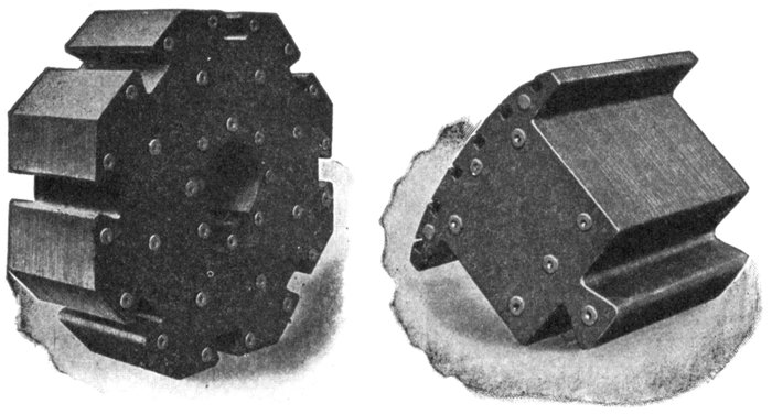
Figs. 1,448 and 1,449.—Westinghouse laminated hub and laminated pole piece for revolving field having squirrel cage winding. Thin steel is used for the laminations of both hub and pole piece; these are assembled and firmly riveted together under hydraulic pressure. The laminations are of the same thickness in both hub and spider.
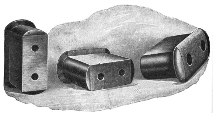
Figs. 1,450 to 1,452.—Views of Triumph pole pieces. These consist of laminated punchings securely clamped between two cast steel end plates. The laminations are shaped with polar horns or shoes as shown, and which serve to keep the field coils securely wedged in position. In some designs the horns are separate. The two holes in each pole piece are for through bolts which secure the pole piece and coil to the spider run. Dovetail joints are sometimes used instead of through bolts, as in figs. 1,448 and 1,449.
Ques. What is a self-excited alternator?
Ans. One in which the field magnets are excited by current from one or more of the armature coils, or from a separate winding (small in comparison with the main winding), the current being transformed into direct current by passing it through a commutator.
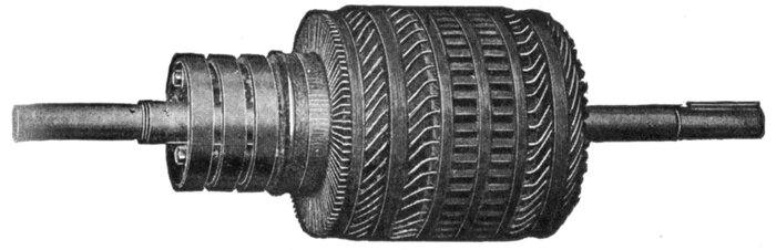
Fig. 1,453.—Fort Wayne armature for self-excited alternator. There are two independent windings, one for the main current, and one for the exciting current. The winding for the latter current occupies a very small amount of space, and is placed in the slots on top the main winding. The commutator to which the exciter winding is connected, is located between the collector rings and the core. It is of standard construction with end clamps holding the bars in place on the insulated commutator drum. The armature coils are form wound and the core is built of sheet steel laminations, annealed and japanned to prevent hysteresis and eddy current losses. Ventilated openings are provided to allow a free circulation of air both around the ends of the windings and through ducts in the laminated core. The core is clamped by bolts between the flanges of the armature spider which is keyed to the shaft. These flanges have cylindrical extensions with ribbed surfaces, which form a support for the ends of the armature coils. The ribbed surfaces form air passages from the core outward around the ends of the coils, thus ventilating both core and coils.
Fig. 1,453 shows an armature of a self-excited machine, the exciting current being generated in a separate winding and passed through a commutator.
Ques. For what class of service are self-exciting alternators used?
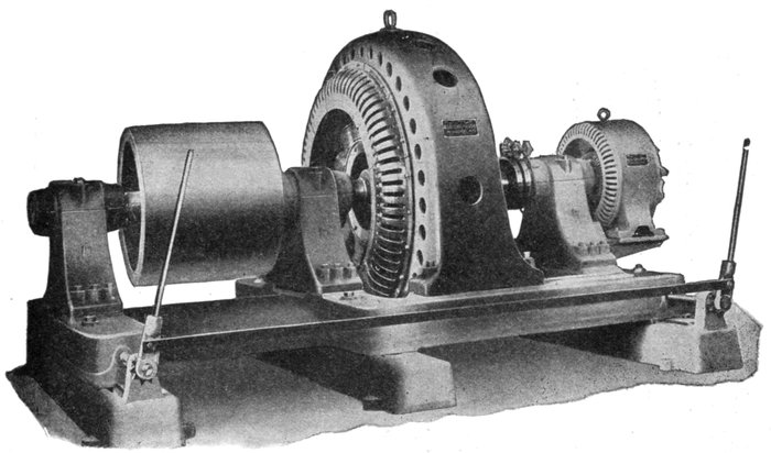
Fig. 1,454.—Allis-Chalmers three bearing type alternator with exciter direct connected. The bearing pedestals are bolted to a substantial cast iron base having, in the large sizes, sufficient length to permit shifting frame sideways along the base to give access to the field and armature coils. The field coils are designed for 120 volt excitation, and are wound edgewise with copper strip. There is a liberal margin of field excitation to take care of overloads or for operation on loads of low power factor. The regulating qualities are as good as can be obtained without making the machine unnecessarily large and expensive. By regulation is meant the percentage rise in voltage when full load is thrown off, field excitation and speed being held constant; the percentage is referred to normal full load voltage. An alternator with poor regulation will show large variations in voltage with changes in load, the pressure falling whenever a load is thrown on and rising when it is thrown off. These changes will be especially pronounced if the load be inductive. A badly designed alternator might show very fair regulation on non-inductive load and yet be unable to give full voltage on inductive load.
Ans. They are employed in small power plants and isolated lighting plants where inductive loads are encountered.
Ques. What is a separately excited alternator?
Ans. One in which the field magnets are excited from a small dynamo independently driven or driven by the alternator shaft, either direct connected or by belt as shown in fig. 1,455.
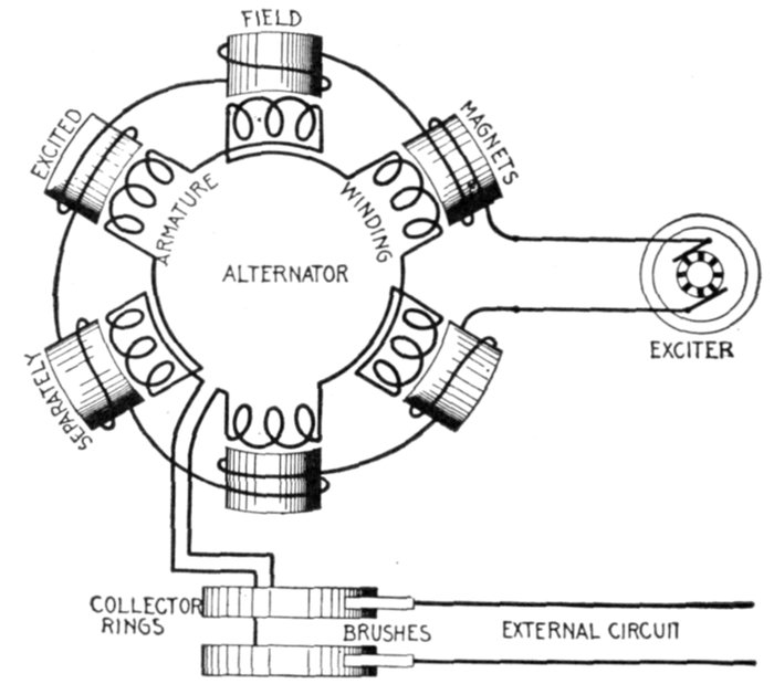
Fig. 1,455.—Diagram of separately excited alternator. The field winding is supplied with direct current, usually at 125 volts pressure by a small dynamo called the "exciter." The latter may be driven by independent power, or by belt connection with the main shaft, and in some cases the exciter is directly connected to the alternator shaft.
Ques. What is a compositely excited alternator?
Ans. A composite alternator is similar to a compound wound dynamo in that it has two field windings. In addition to the regular field coils which carry the main magnetizing current from the exciter, there is a second winding upon two or upon all of the pole pieces, carrying a rectified current from the alternator which strengthens the field to balance the losses in the machine, and also if so desired, the losses on the line as shown in fig. 1,456.
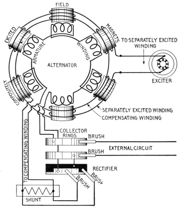
Fig. 1,456.—Diagram of compositely excited alternator. The current for exciting the field magnets is obtained, partly from an exciter and partly from the windings of the alternator, being transformed into direct current by the rectifier. The connections are as shown. One end of the armature winding is connected to one of the collector rings; the other end, to the light part of the rectifier, as shown, the solid black part of the rectifier being connected to the other collector ring. Two brushes bear on adjacent teeth of the rectifier and are connected to the compensating winding circuit across which is a shunt. These connections are shown more clearly in fig. 1,457. In operation the separately excited coils set up the magnetism necessary for the generation of the voltage at no load. The main current coming from the armature is shunted, part going through the shunts and the remainder around the compensating winding, furnishing the additional magnetism necessary to supply the voltage to overcome the armature impedance. This composite method of field excitation is very similar to that used on a compound wound dynamo. As shown, both field windings encircle every pole, but in some machines the rectified current will traverse a few poles only, the current from the exciter traversing the remainder.
Ques. What is a magneto?
Ans. A special form of alternator having permanent magnets for its field, and used chiefly to furnish current for gas engine ignition and for telephone call bells.
Details of construction and operation are shown in figs. 1,458 to 1,461.
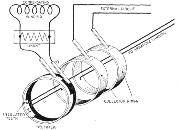
Fig. 1,457.—Diagram showing construction of rectifier and connections of compositely excited alternator. The rectifier consists of two castings M and S with teeth which fit together as shown, being insulated so they do not come in contact with each other. Every alternate tooth being of the same casting is connected together, the same as though joined by a conducting wire. There are as many teeth as there are poles. One end of the armature winding is connected direct to one of the collector rings, while the other is connected to M of the rectifier, the circuit being through brushes P and Q, the shunt, and compensating winding to the other collector ring. The brushes P and Q contact with adjacent teeth, when one is in contact with the solid black casting the other touches the light casting. The principle of action is the same as a commutator, briefly: to reverse the connections terminating at the brushes P and Q in synchronism with the reversals of the alternating current induced in the armature winding, thus obtaining direct current for the compensating field winding. The shunt resistance placed across the compensating winding circuit permits adjusting the compounding of the machine to the circuit on which it is to work, since by varying the resistance the percentage of the total current passing through the compensating winding can be changed. It will be seen by tracing the path of the current for each direction in the armature winding that while the rectifier causes the current to flow in the same direction in the compensating field winding, it still remains alternating in the external circuit.
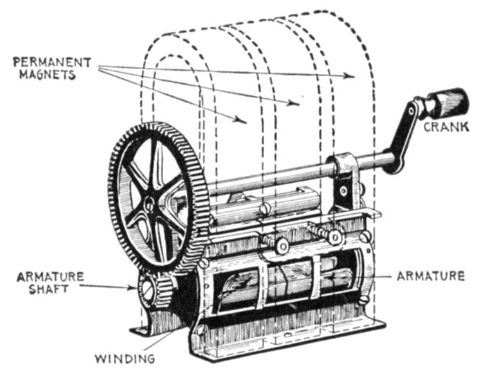
Fig. 1,458.—Connecticut magneto; view showing permanent magnets in dotted lines. It consists of three permanent U shape magnets, between the poles of which is a shuttle type armature. The latter is geared to a hand crank in sufficient velocity ratio to give the desired speed without too rapid turning of the crank. This type of magneto is used to generate current for operation of telephone call bells.
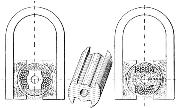
Figs. 1,459 to 1,461.—Diagram illustrating the operation of a magneto. The shuttle shaped armature is wound from end to end with insulated wire, so that when rotated, a powerful alternating current is produced in the windings by cutting the magnetic lines, whose varying strength is shown by the shaded portions in the two views. When in the position shown in the first diagram, the lines of force mostly converge at the top and bottom, finding a direct path through the metal end flanges of the shuttle. When in the position shown in the second diagram, the lines are converged so as to pass through the armature core. Fig. 1,460 shows detail of the armature core.
Ques. What are the two principal types of field magnet?
Ans. Stationary and revolving.
Ques. What is the usual construction of stationary field magnets?
Ans. Laminated pole pieces are used, each pole being made up of a number of steel stampings riveted together and bolted or preferably cast into the frame of the machine. The field coils are machine wound and carefully insulated. After winding they are taped to protect them from mechanical injury. Each coil is then dipped in an insulating compound and afterwards baked to render it impervious to moisture.
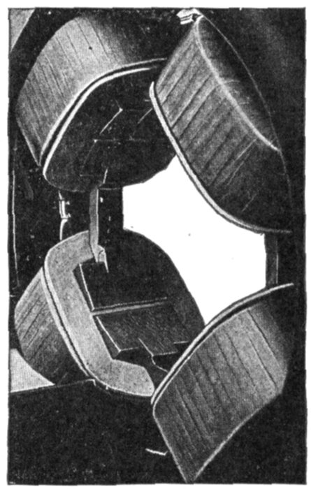
Fig. 1,462.—Stationary field of Fort Wayne multiphase revolving armature alternator; view showing brass girds on pole pieces for synchronous motor operation. When designed for this use the machine is provided with amortisseur winding on the poles. As shown in the illustration this winding consists of a brass collar around the pole tip with a cross rib integral with the collar, fitting in a slot in the pole face parallel to the shaft. This construction assists in bringing the machine up to synchronous speed as an induction motor, ordinarily checks any tendency toward hunting and does not in any way affect the operation of the machine as an alternator. The main field winding should be connected through switches on the field frame in order that the field circuit may be broken up to eliminate any danger that might arise from induced voltage. It is not advisable to throw on a full rated voltage and a compensator should, therefore, be provided to reduce the pressure.
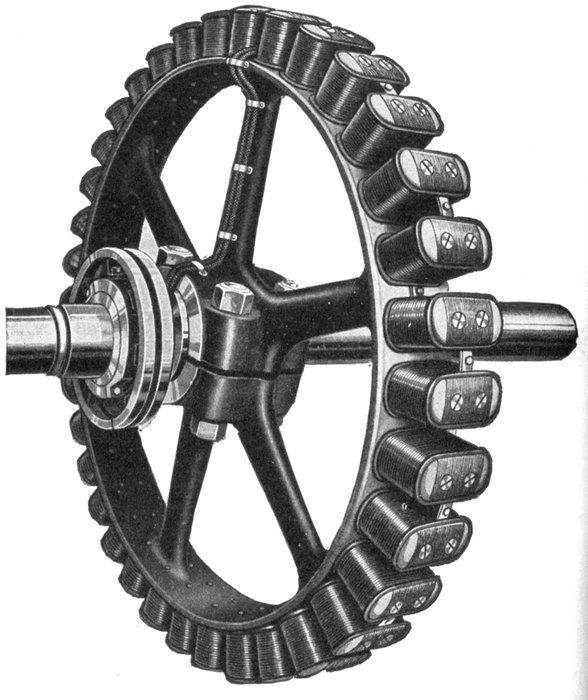
Fig. 1,463.—Triumph 36 pole fly wheel type revolving field. The spider has the form of a fly wheel having spokes and rim to which the field magnets are attached by through bolts. The field coils are of copper strap bent on end, the kind generally used on large machines. The series connection of the coils is plainly shown, also the two cables leading via one of the spokes to the slip rings.
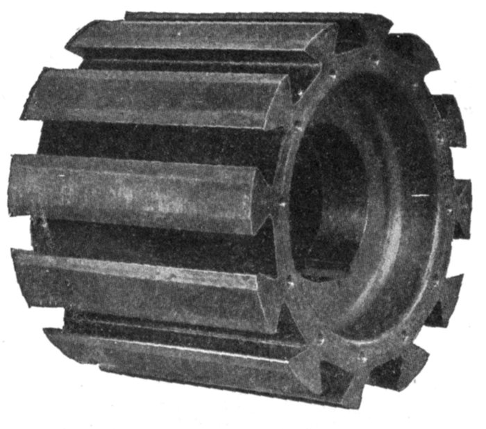
Fig. 1,464.—Wagner cast steel hub with dovetail grooves for attaching the revolving field magnets. Such construction is generally used on machines of small and medium size.
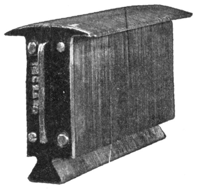
Fig. 1,465.—Wagner laminated pole piece with horns stamped in one piece. The laminations are held together between two end pieces by through rivets, as shown.
Ques. Describe the construction of a revolving field.
Ans. The entire structure or rotor consists of a shaft, hub or spider, field magnets and slip rings. The magnet poles consist of laminated iron stampings clamped in place by means of through bolts which, acting through the agency of steel end plates, force the laminated stampings into a uniform, rigid mass. This mass is magnetically subdivided into so many small parts that the heating effect of eddy currents is reduced to a minimum. The cores are mounted upon a hub or spider either by dovetail construction or by means of through bolts, according to the centrifugal force which they must withstand in operation, either method permitting the easy removal of any particular field pole if necessary. The field coils are secured upon the pole pieces either by horns in one piece with the laminations, or separate and bolted. All the coils are connected in series, cable leads connecting them to slip rings placed on the shaft.
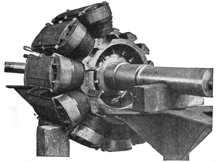
Fig. 1,466.—Wagner revolving field of 300 kilowatt alternator during construction, illustrating the method of attaching the field magnets to the hub by dovetail joints. After the notched ends of the pole pieces are slid into the grooves in the hub, tapered keys, which are plainly seen, are driven in, thus making a tight joint which will not shake loose.
Ques. What are slip rings?
Ans. Insulated rings mounted upon the alternator shaft to receive direct current for the revolving field, as distinguished from collector rings which collect the alternating currents generated in an alternator of the revolving armature type.
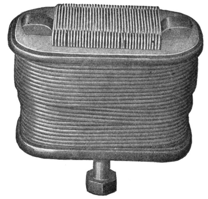
Fig. 1,467.—General Electric field coil, showing one method of winding. In the smaller machines the wire is wound on spools which are slipped over the pole pieces, which are built of sheet iron, spreading at the pole face so as to secure not only a wide polar arc for the proper distribution of the magnetic flux, but also to hold the field windings in place.
In construction provision is made for attaching the field winding leads. The rings are usually made of cast iron and are supported mechanically upon the shaft, but are insulated from it and from one another.
The current is introduced by means of brushes as with a commutator. Carbon brushes are generally used.
A good design of slip ring should provide for air circulation underneath and between the rings.
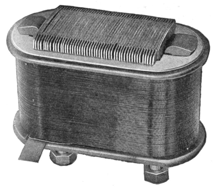
Fig. 1,468.—General Electric field coil showing another method of winding. The field coils on the larger machines consist of a single strip of flat copper, wound on edge as shown, so that the surface of every turn is exposed to the air for cooling. The flat sides of the copper strip rest against each other and the entire coil forms a structure of great solidity which can be easily removed for inspection and repair.
Ques. What form of spider is used on large alternators?
Ans. It is practically the same form as a fly wheel, consisting of hub, spokes, and rim to which the magnets are bolted.
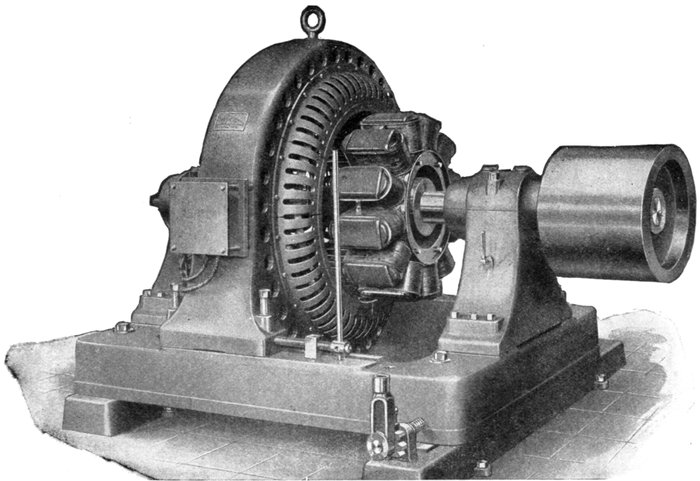
Fig. 1,469.—Allis-Chalmers 60 kva. belted two bearing alternator on base arranged so the armature can be shifted sideways as shown, to give access to the field and armature coils.
On alternators of the fly wheel type the spider rim is made of sufficient weight to obtain full fly wheel effect, thus making a separate fly wheel unnecessary.
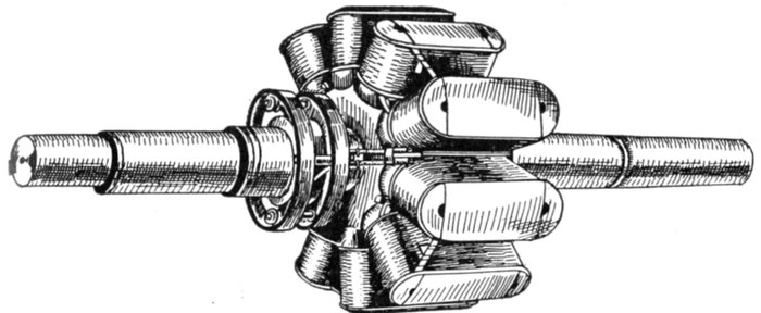
Fig. 1,470.—Revolving field of Fort Wayne 10 pole alternator. In construction, the cores of the field poles are built up from punchings of laminated steel, and assembled under considerable pressure between malleable iron or steel end plates and riveted together. Substantial insulation is placed on the pole cores and over this is wound the field coils of cotton covered wire. After the wire is in place, the completed poles are baked to expel any moisture and are then treated with insulating varnish. They are then assembled on a laminated spider, being held in place by dovetail joints made tight by the use of taper keys. Special casting plates are finally fastened in place over the dove tails effectually closing them. The assembly of the field is completed by the insertion of the shaft into the field spider under heavy hydraulic pressure. All the coils are connected in series, cable leads connecting them to slip rings placed on the shaft. Each slip ring is provided with a double type brush holder, making it possible to clean brushes while the alternator is in service, by simply removing one brush at a time.
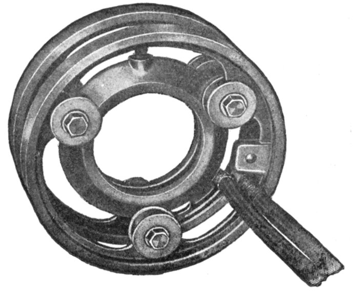
Fig. 1,471.—General Electric slip rings; view showing construction and attachment of cable leads to field winding. They are so designed that all surfaces of the rings have easy access to the air, in order to obtain good ventilation. Slip rings, through which current is transmitted to a revolving field, are to be distinguished from collector rings whose function it is to "collect" or transmit the alternating currents induced in the armature to the brushes.
Armatures.—In construction, armatures for alternators are similar to those employed on dynamos; they are in most cases simpler than direct current armatures due to the smaller number of coils, absence of commutator with its multi-connections, etc. Alternator armatures may be classified in several ways:
1. With respect to operation, as
a. Revolving;
b. Stationary.
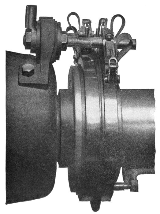
Fig. 1,472.—Allis-Chalmers brush holder and slip rings. The latter are made of cast copper, which the builders claim to be more satisfactory than cast iron. On some of the large low speed machines the collector rings are split, but on the majority of alternators they are in one piece. Current is led into the rings by means of carbon brushes, the number of brushes being such that the current density at the rubbing contact is kept within conservative limits. At least two brushes per ring are provided, so that one can be removed for inspection without interrupting the exciting current. In large machines the brush holder studs are mounted on a stand supported from the base; on small alternators they are usually fastened to the cap of one of the bearing pedestals.
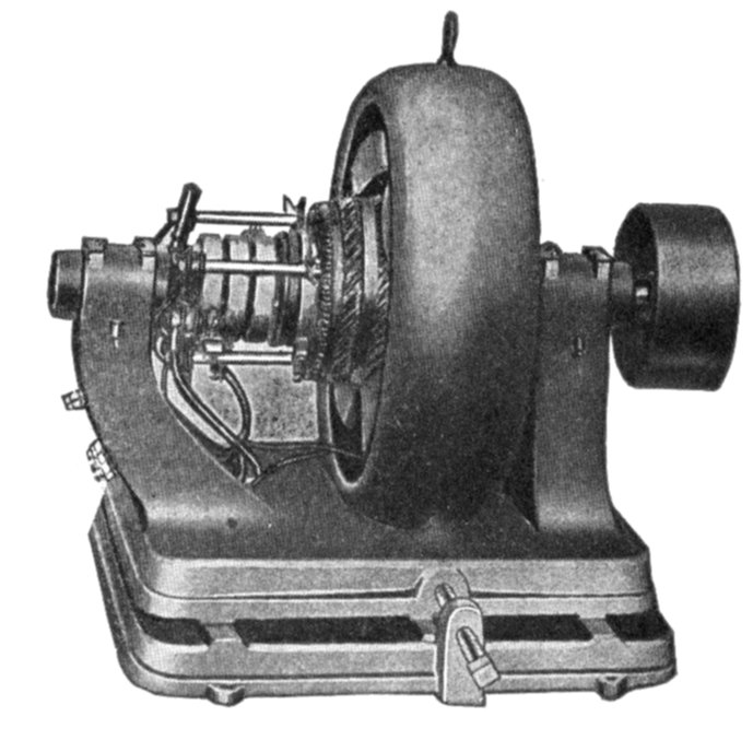
Fig. 1,473.—Fort Wayne multiphase revolving armature alternator, designed for use in small power plants and isolated lighting plants where inductive loads are encountered. Built for pressures of 120, 240, 480, and 600 volts. These voltages have been recommended by the American Institute of Electrical Engineers, and will cover the needs of any set of conditions ordinarily met with. These standard voltages not only permit economical distribution, but they are such that no transformers are necessary to reduce the line pressure for ordinary cases. For transmitting power relatively long distances, 600 volts is usually employed. Where there is a demand for 480 volt service, a 480 volt alternator should be selected and if lower voltages are also desired an auto-transformer may be furnished by means of which 240 volts can be obtained. When 120 volt circuits are necessary for lighting, etc., the 240 volt pressure can be still further reduced to 120 volts by means of another auto-transformer. However, this double reduction will rarely be found necessary.
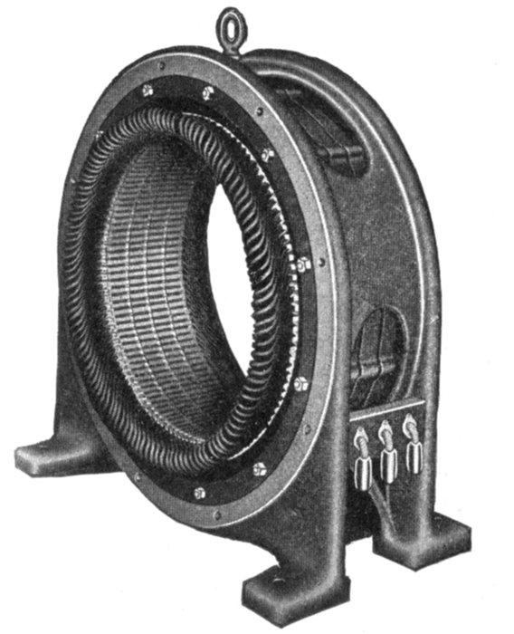
Fig. 1,474.—Western Electric stationary armature. In this type of armature, the core upon which the winding is placed, is built into the frame as shown, the core teeth projecting inwardly like internal gear teeth, forming a cylindrical chamber for the revolving field. The core is built up of iron, laminated and japanned to prevent eddy currents and hysteresis losses. The laminations are rigidly bolted between two heavy end plates. The armature coils are of copper bar impregnated with insulating compound. They are held in the slots by wedges which allow their ready removal for inspection or repairs.
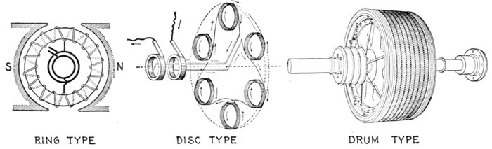
Figs. 1,474 to 1,477.—Various types of armature; fig. 1,474 ring armature; fig. 1,475 disc armature; fig. 1,476 drum armature. The latter type is now almost universally used, the others being practically obsolete. A Gramme ring wound and connected to collector rings as in fig. 1,474, will yield an alternating current. In a multipolar field, the ring will need multipolar connections alternated at points corresponding to the pitch of the poles. Fig. 1,475 illustrates the so-called "Siemens" disc armature. The armature coils are arranged around the periphery of a thin disc. The field magnets consist of two crowns of fixed coils, with iron cores arranged so that their free poles are opposite one another. This type was created in 1878 by Herr von Hefner, engineer to Messrs. Siemens and Halske. Fig, 1,476 shows a modern drum armature of a three phase machine. It is similar in appearance to a direct current armature except for the absence of the commutator and its connections. The drum armature is the prevailing type.
2. With respect to the core, as
a. Ring;
b. Disc;
c. Drum.
Ring and disc armatures are practically obsolete and need not be further considered. A ring armature has the inherent defect that the copper inside the ring is inactive.
Disc armatures were employed by Pacinotti in 1878, and afterwards adopted by Brush in his arc lighting dynamos.
The design failed for mechanical reasons, but electrically it is, in a sense, an improvement upon the Gramme ring, in that inductors on both sides of the ring are active, these being connected together by circumferential connectors from pole to pole, thus, corresponding to the end connectors on modern drum armatures.
3. With respect to the core surface, as
a. Smooth core;
b. Slotted core.
In early dynamos the armature windings were placed upon an iron core with a smooth surface. A chief disadvantage of this arrangement is that the magnetic drag comes upon the inductors and tends to displace them around the armature. To prevent
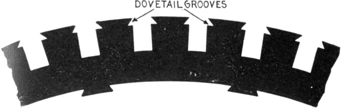
Fig. 1,478.—A style of disc largely used for armature cores. The teeth are provided with dovetail grooves near the circumference. After the coil is inserted in a groove, a wooden wedge is driven in the groove which encloses the coil and secures it firmly in position. This obviates the necessity of bands to resist the centrifugal force acting on the inductors.
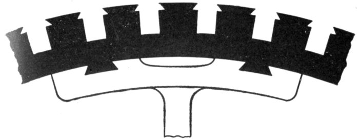
Fig. 1,479.—Large revolving armature construction with segmental discs dovetailed to spider spokes.
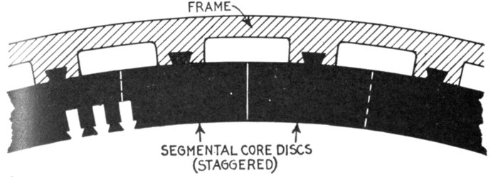
Fig. 1,480.—Construction of large stationary armature; view showing section of core and frame. The core discs are in segments and are attached to the frame by dovetail joints as shown. The joints are staggered in building up the core, that is, they are overlapped so as not to unduly increase the reluctance of the magnetic circuit. Dovetail joints obviate the use of through bolts which, if not insulated, are liable to give rise to eddy currents by short circuiting the discs.
this, projecting metal pieces called driving horns were fixed into the core so as to take the pressure, but they proved unsatisfactory. This defect together with the long air gap necessary in smooth core construction resulted in the type being displaced by slotted core armatures.
A slotted core is one whose surface is provided with slots or teeth which carry the inductors, as shown in the accompanying illustrations, and is the type almost universally used. The inductors are laid in the slots, the sides and bottoms of which are first carefully insulated by troughs of mica-canvas, micanite or other suitable insulating material.
Ques. What are the advantages of slotted core armatures?
Ans. The teeth protect the inductors, retain them in place against the electrical drag and centrifugal force, and the construction permits a reduction of air gap to a minimum, thus reducing the amount of copper required for the field.
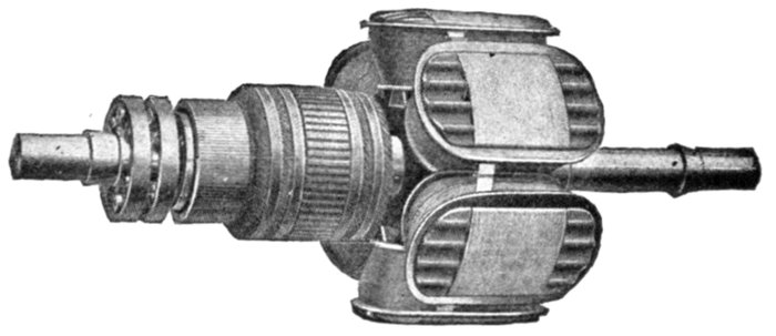
Fig. 1,481.—General Electric revolving field and exciter armature. This is an example of direct connected exciter construction. In this arrangement the armature of the exciter is carried on the alternator shaft at the end farthest from the pulley. In the smaller sizes the magnet frame is bolted to the bearing bracket, but in the larger sizes special construction is used depending upon the conditions to be met. On all alternators of standard design, the field is built for 125 volts excitation and on account of the increased danger from induced voltage, in case the machine is used as a synchronous motor, the builders consider any higher voltage undesirable.
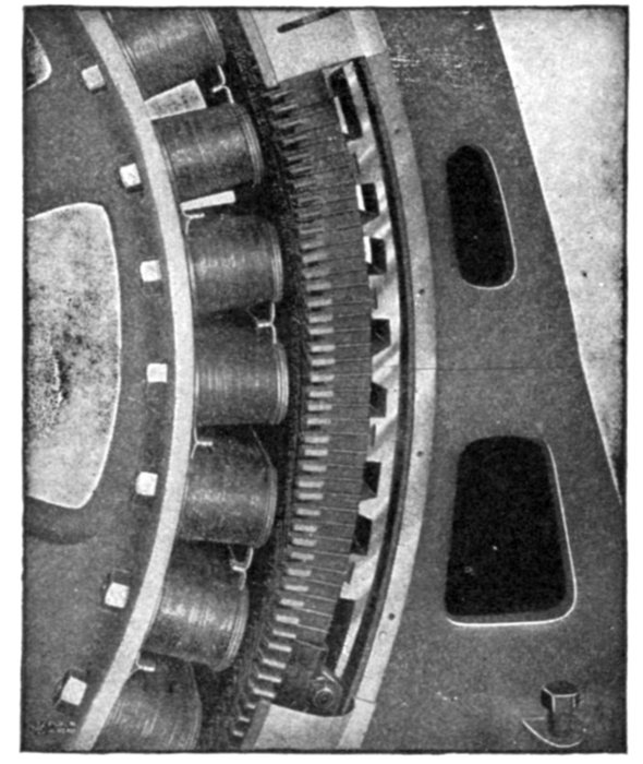
Fig. 1,482.—Section of General Electric Alternator showing method of dovetailing core laminations to frame. The latter is made in two general styles, known as the box type and skeleton type. The box type consists of a single casting for the smaller sizes, but for large capacity alternators the frame castings are usually divided into upper and lower sections. The skeleton type consists of two side castings between which substantial spacing rods are set at regular intervals. The core consists of the usual sheet iron lamination slotted and assembled; they are mounted on the inner periphery of the frame, making lap joints (that is "staggered" as in fig. 1,480), each section being dovetailed to the frame. Heavy clamping rings or end plates are mounted on both sides of the core by means of bolts, and supporting fingers extend along the slot projections. The design is such as to provide for air circulation as shown in figs. 1,483 and 1,484.
Armature Windings.—In general, the schemes for armature windings for alternators are simpler than those for direct current machines, as in the majority of cases the inductors are an even multiple of the number of poles, and the groupings are usually symmetrical with respect to each pole or each pair of poles. Furthermore, as a general rule, all the inductors of any one phase are in series with one another; therefore, there is only one circuit per phase, and this is as it should be, since alternators are usually required to generate high voltages. These general principles establish the rule, that in the circuit in a single phase armature, and in the individual circuits in a polyphase armature, the winding is never re-entrant, but the circuits have definite endings and beginnings. In exceptional cases, as those of polyphase converters, re-entrant circuits are employed, and the armature windings are so constructed that a commutator can be connected to them exactly as in direct current machines. These armatures are usually of the lap wound drum type.
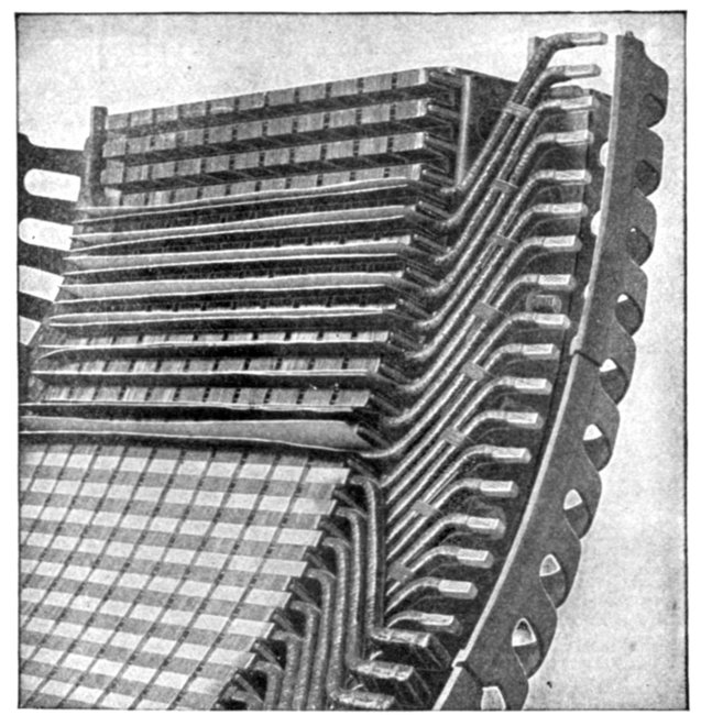
Fig. 1,483.—Section of General Electric alternator frame showing air ducts and supporting fingers extending along the slot projections. The air circulation is provided for by means of ducts formed by suitable spacing blocks inserted at intervals between the laminations, as shown here and in fig. 1,484. The armature coils are form wound and designed so they can be readily replaced in case of injury. They are taped and treated with an impregnating compound, in the usual way, then inserted in the armature slots in an armour of horn fibre and retaining wedges of wood are dovetailed into the slot walls.
Alternator windings are usually described in terms of the number of slots per phase per pole. For instance, if the armature of a 20 pole three phase machine have 300 slots, it has 15 slots per pole or 5 slots per each phase per pole, and will be described as a five slot winding. Therefore, in order to trace the connections of a winding, it is necessary to consider the number of slots per pole for any one phase on one of the following assumptions: 1, that each slot holds one inductor; 2, that there is one side of a coil in each slot; and 3, that one side of a coil is subdivided so as to permit of its distribution in two or more adjacent slots.
The voltage depends upon the number of inductors in a slot, but the breadth coefficient and wave form are influenced by the number of slots per pole, and not by the number of inductors within the slots.
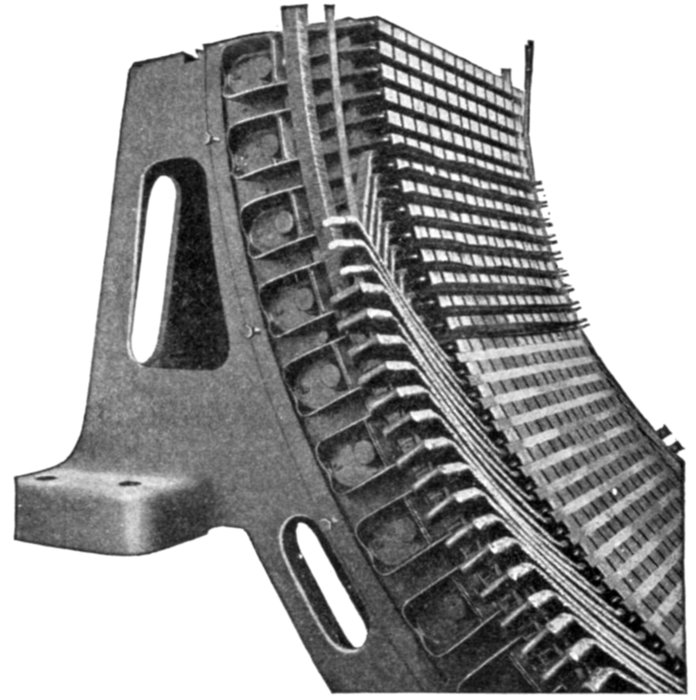
Fig. 1,484.—Section of General Electric stationary armature showing method of assembling the coils. These are form wound and are held in the slots by suitable wedges, the open slot construction permitting the use of form wound coils that can be easily removed and replaced in case of damage. Where heavy windings project beyond the laminations, an additional support is provided by means of an insulated metal ring, to which the outer ends of the coils are fastened; the coils are thereby protected from mechanical displacement, or distortion due to the magnetic disturbances caused by violent fluctuations of the load or short circuits. The figure shows a section of a supporting ring of this type and indicates the method of connecting the coils to it. In order to admit of the prompt replacement of damaged coils, sufficient space is usually provided between the alternator bearings to allow ample movement of the armature to permit of ready access to both armature and field coils. Where space necessitates the use of a short shaft, access to the windings may be had by disconnecting some of the coils and lifting the upper half of the armature.
Classification of Windings.—The fact that alternators are built in so many different types, gives rise to numerous kinds of armature winding to meet the varied conditions of operation. In dividing these forms of winding into distinctive groups, they may be classified, according to several points of view, as follows:
1. With respect to the form of the armature, as:
a. Revolving;
b. Stationary.
2. With respect to the mode of progression, as:
a. Lap winding;
b. Wave winding.
3. With respect to the relation between number of poles and number of coils, as:
a. Half coil winding;
b. Whole coil winding.
4. With respect to the number of slots, as:
a. Concentrated or uni-coil winding;
b. Distributed or multi-coil winding.
Partially distributed;
Fully distributed.
5. With respect to the form of the inductors, as:
a. Wire winding;
b. Strap winding;
c. Bar winding.
6. With respect to the number of coils per phase per pole, as:
a. One slot winding;
b. Two slot winding;
etc.
7. With respect to the kind of current delivered, as:
a. Single phase winding;
b. Two phase winding;
c. Three phase winding.
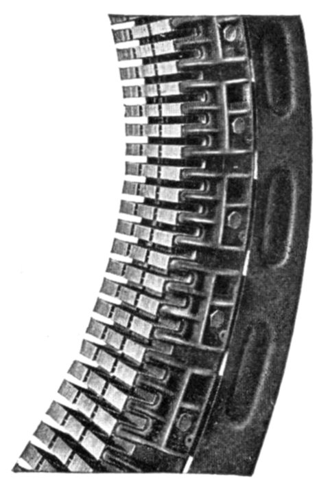
Fig. 1,485.—Section of Western Electric stationary armature core showing laminations clamped in place, and ventilating ducts. The stator or stationary armature consists of soft iron laminations assembled in the magnet frame with stator coils embedded in the core slots. The laminations are punched separately and then carefully annealed to reduce hysteresis losses. After annealing, a coat of japan is applied, effectively preventing the flow of eddy currents in the assembled core. The frame is cast iron and of the box type construction. The frames of the smaller sizes are cast in one piece, while frames of the larger sizes are split to facilitate installation. Large openings are provided in the box type frame, in order to improve the ventilation. The laminations are securely held in place in the frame by heavy end rings and by steel clamping fingers which are firmly bolted to the frame. The outer circumference of the core is dovetailed to the frame, and the inner circumference is slotted to receive the windings. The alignment of the slots is insured by means of metal wedges, and no filing is done on the slots, so that each lamination is always insulated from the next one. Numerous ventilating ducts allow the free circulation of cool air through and around the coils. The open slot construction is employed and the coils are fitted into insulating troughs which offer excellent mechanical and electric protection. The coils are held in place by suitable wedges.
8. With respect to the shape of the coil ends, as:
a. Single range;
b. Two range;
etc.
In addition to these several classes of winding, there are a number of miscellaneous windings of which the following might be mentioned:
a. Chain or basket winding;
b. Skew coil winding;
c. Fed-in winding;
d. Imbricated winding;
e. Mummified winding;
f. Spiral winding;
g. Shuttle winding;
h. Creeping winding;
i. Turbine alternator winding.
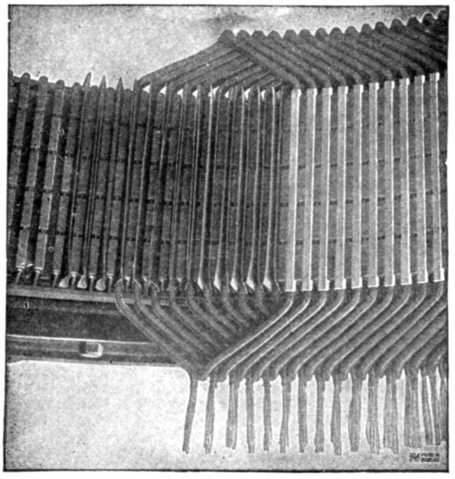
Fig. 1,486.—Method of assembling form wound coils. The picture shows a section of a General Electric armature with part of the coils in place. A layer of insulating material is first placed in the slots, before inserting the coils as seen at the left. When the coils are in place and surrounded by this layer of insulating material the retaining wedges are inserted in the notches, thus closing the slots and protecting the coils from mechanical injury. A few wedges are seen in position at the right.
Ques. Define a revolving and a stationary winding.
Ans. The words are self-defining; a winding is said to be revolving or stationary according as the armature forms the rotor or stator of the machine.
Ques. What is the significance of the terms lap and wave as applied to alternator windings?
Ans. They have the same meaning as they do when applied to dynamo windings.
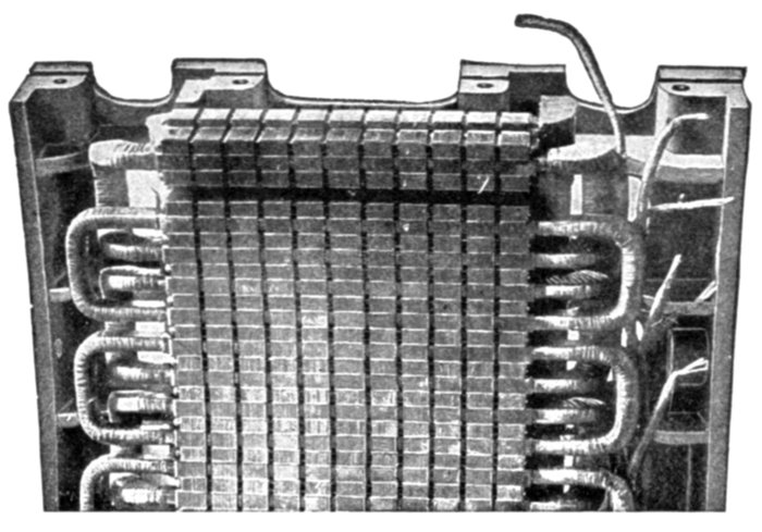
Fig. 1,487.—Section of General Electric stationary armature ventilating ducts and winding in position.
These are described in detail in Chapter XVIII. Briefly a lap winding is one composed of lap coils; a wave winding is one which roughly resembles in its diagram, a section of waves.
Half Coil and Whole Coil Windings.—The distinction as to whether the adjacent sides of consecutive coils are placed together under one pole or whether they are separated a distance equal to the pole pitch, gives rise to what is known as half coil and whole coil windings.
A half coil or hemitropic winding is one in which the coils in any phase are situated opposite every other pole, that is, a winding in which there is only one coil per phase per pair of poles, as in fig. 1,488.
A whole coil winding is one in which there is one coil per phase per pole, as in fig. 1,489, the whole (every one) of the poles being subtended by coils.
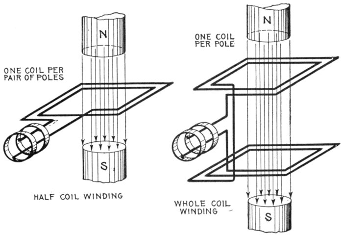
Figs. 1,488 and 1,489.—Elementary bipolar alternators with half coil and whole coil windings. In a half coil winding there is one coil per phase per pair of poles; in a whole coil winding there is one coil per phase per pole.
Concentrated or Uni-Coil Winding.—Fig. 1,492 shows the simplest type of single phase winding. It is a one slot winding and is sometimes called "monotooth" or "uni-coil" winding. The surface of the armature is considered as divided into a series of large teeth, one tooth to each pole, and each tooth is wound with one coil, of one or more turns per pole. Since all the turns of the coil are placed in single slots, the winding is called "concentrated."
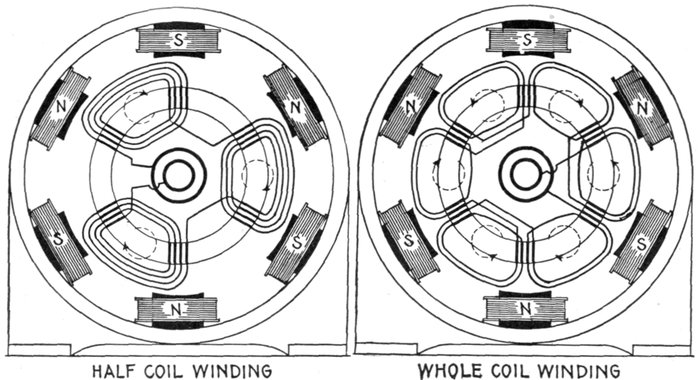
Fig. 1,490.—Multi-polar revolving armature alternator with half coil winding, shown in radially developed diagram to clearly indicate the path of the winding. A half coil or hemitropic winding has a slightly higher reactance than a winding in which two distinct coils are used in the same slot, one going forward and the other backward. The most usual three phase windings are of the half coil type as the three sets of coils are equispaced over a pair of poles.
Fig. 1,491.—Multi-polar revolving armature alternator with whole coil winding shown in radially developed diagram to clearly indicate the path of the winding.
Ques. What are the features of concentrated windings?
Ans. Cheap construction, maximum voltage for a given number of inductors. Concentrated windings have greater armature reaction and inductance than other types hence the terminal voltage of an alternator with concentrated winding falls off more than with distributed winding when the current output is increased. An alternator, therefore, does not have as good regulation with concentrated winding as with distributed winding.
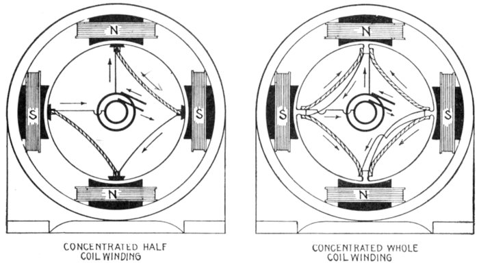
Figs. 1,492 and 1,493.—Concentrated windings. A concentrated winding is one in which the armature has only one tooth per phase per pole, that is, the number of teeth equals the number of poles. A concentrated winding of the half coil type has only one side of a coil in each slot as in fig. 1,492. In the whole coil variety, each slot contains neighboring sides of adjacent coils, as in fig. 1,493. In construction, wedges are generally used for retaining the half coils, and with whole coils the teeth have projecting horns for this purpose.
Ques. What should be noted with respect to concentrated windings?
Ans. A concentrated winding, though giving higher voltage than the distributed type with no load, may give a lower voltage than the latter at full load.
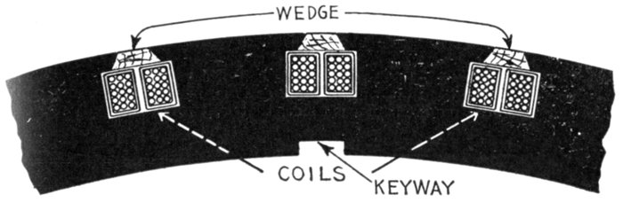
Fig. 1,494.—Laminated core with two coils in position; type of punchings used on some machines having concentrated whole coil windings. The manner of assembling the coils is shown in fig. 1,495.
Ques. What is the wave form with a concentrated winding?
Ans. The pressure curve rises suddenly in value as the armature slots pass under the pole pieces, and falls suddenly as the armature slots recede from under the pole pieces.
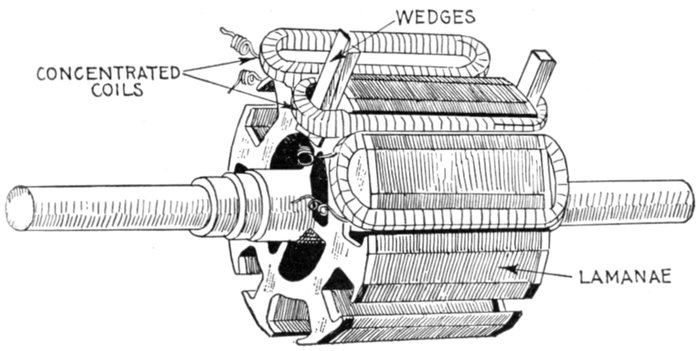
Fig. 1,495.—Westinghouse single phase concentrated coil armature; view showing method of placing coils. The coils are machine wound on formers and after being taped, varnished and baked, are spread out slightly so as to pass over the teeth and are then forced into place in the deep slots by means of wooden wedges, being securely held in place by retaining wedges, as shown in fig. 1,494.
Distributed or Multi-Coil Windings.—Instead of winding an armature so it will occupy only one slot per phase per pole, it may be spread out so as to fill several slots per phase per pole. This arrangement is called a distributed winding.
To illustrate, fig. 1,496 represents a coil of say fifteen turns. This could be placed on an armature just as it is, in which case only one slot would be required for each side, that is, two in all. In place of this thick coil, the wire could be divided into several coils of a lesser number of turns each, arranged as in fig. 1,497; it is then said to be partially distributed, or it could be arranged as in fig. 1,498, when it is said to be fully distributed.
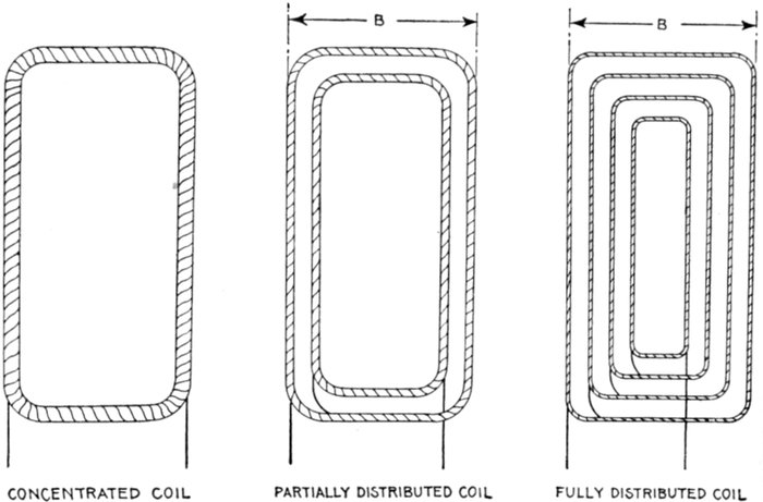
Figs. 1,496 to 1,498.—Alternator coils, showing difference between the concentrated, partially distributed, and fully distributed forms. Fig. 1,496 shows a concentrated coil in which all the wire is wound in one large coil; in the partially distributed type fig. 1,497, the wire of fig. 1,496, is wound in two or more coils or "sections" connected as shown, leaving some space inside not taken up by the subdivisions. In fig. 1,498 the wire of fig. 1,496 is fully distributed, being wound in a series of coils, so that all the interior space is taken up by the wire, that is to say, the spaces not occupied by the wire (the teeth when placed on the armature) are of equal size.
A partially distributed winding, then, is one, as in fig. 1,499, in which the coil slots do not occupy all the circumference of the armature; that is, the core teeth are not continuous.
A fully distributed winding is one in which the entire surface of the core is taken up with slots, as in fig. 1,500.
Ques. In a distributed coil what is understood by the breadth of the coil?
Ans. The distance between the two outer sides, as B in figs. 1,497 and 1,498.
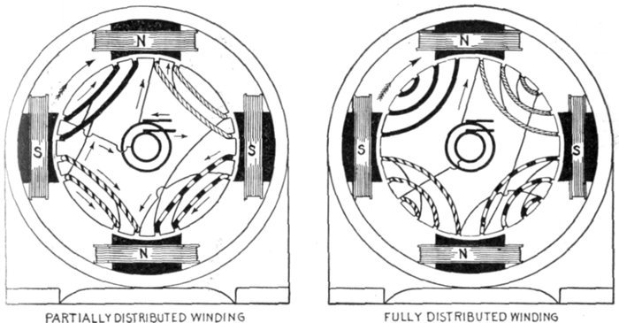
Fig. 1,499.—Partially distributed winding. Each coil unit is here divided into two concentric coils of different dimensions and connected in series, as shown in detail in fig. 1,497. This being a "whole coil" winding the several units are so connected that the winding of adjacent units proceeds in opposite directions, that is, one coil is wound clockwise, and the next counter clockwise, etc., so that the induced currents flow in a common direction as indicated by the arrows for the position shown.
Fig. 1,500.—Fully distributed winding. In this type of winding each coil consists of so many sub-coils that the winding occupies the entire surface of the armature core; that is, there are no extensive spaces unoccupied, the spacing being uniform as shown.
Ques. How far is it advisable to spread distributed coils of a single phase alternator?
Ans. There is not much advantage in reducing the interior breadth much below that of the breadth of the pole faces, nor is there much advantage in making the exterior breadth greater than the pole pitch.
Undue spreading of distributed coils lowers the value of the Kapp coefficient (later explained) by reducing the breadth coefficient and makes necessary a larger number of inductors to obtain the same voltage.
The increase in the number of inductors causes more armature self-induction. From this point of view, it would be preferable to concentrate the winding in fewer slots that were closer together. This, however, would accentuate the distorting and demagnetizing reactions of the armature. Accordingly, between these two disadvantages a compromise is made, as to the extent of distributing the coils and spacing of the teeth, the proportions assigned being those which experience shows best suited to the conditions of operation for which the machine is designed.
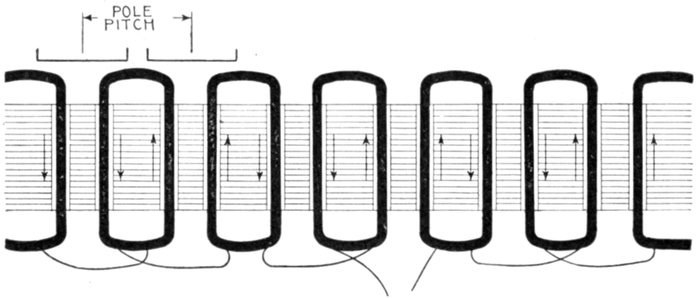
Fig. 1,501.—Developed diagram of single phase concentrated whole coil winding in two slot stamping for six pole alternator. If the sides of adjacent whole coils be slightly separated by placing the winding in a two slot stamping the electrical result will not differ materially from the monotooth whole coil winding, but if the winding be hemitropic, as in fig. 1,502, and has coils of two sizes as shown, it will be suitable for high voltages.
The Kapp Coefficient.—A volt or unit of electric pressure is defined as the pressure induced by the cutting of 100,000,000 or 108 lines of force per second. In the operation of an alternator the maximum pressure generated may be expressed by the following equation:
πfZN
Emax = (1)
108
in which
f = frequency;
Z = number of inductors in series in any one magnetic circuit;
N = magnetic flux, or total number of magnetic lines in one pole or in one magnetic circuit.
The maximum value of the pressure, as expressed in equation (1), occurs when θ = 90°.
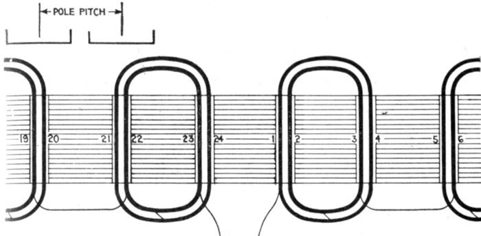
Fig. 1,502.—Developed diagram of single phase partially distributed half coil winding for six pole alternator in two slot stamping, same as in fig. 1,501. In this arrangement the direction of rotation is not reversed. It is a question as to how far the coils of a single-phase armature may be spread with advantage. There is not much advantage in reducing the interior breadth of the coils below that of the pole face, nor in widening the exterior breadth beyond that of the pole pitch.
The virtual value of the volts is equal to the maximum value divided by √2, or multiplied by ½ √2, hence,
½ √2 × πfZN 2.22fZN
Evirt = = (2)
108 108
This is usually taken as the fundamental equation in designing alternators. It is, however, deduced on the assumptions that the distribution of the magnetic flux follows a sine law, and that the whole of the loops of active inductors in the armature circuit acts simultaneously, that is to say, the winding is concentrated.
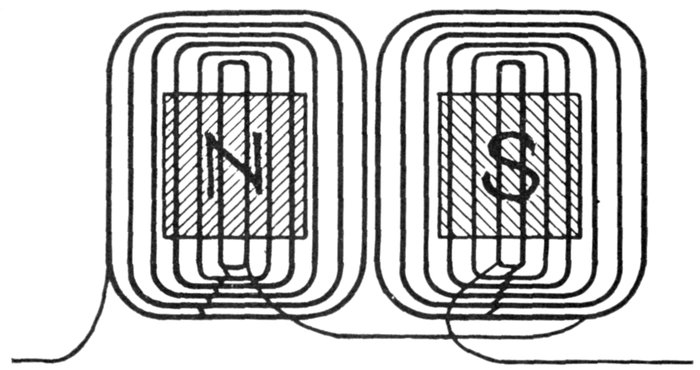
Fig. 1,503.—Developed diagram of single phase winding with fully distributed coils. As explained, excessive spreading lowers the value of the "Kapp" coefficient, and consequently the voltage; also the use of a larger number of inductors to obtain the same voltage results in an increase of armature self-induction. On the other hand, if the winding were concentrated in fewer slots and these slots were closer together, the result will be an increase in distorting and demagnetizing reactions of the armature. Therefore, a compromise between these two disadvantages must be made. The common practice is to wind in two or three slots per pole per phase.
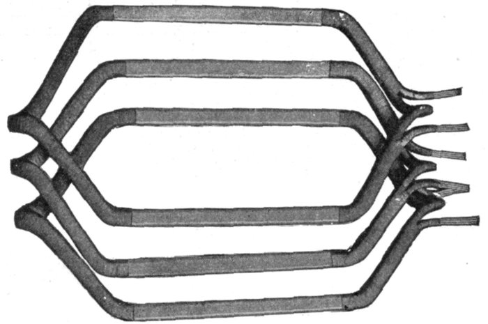
Fig. 1,504.—Allis-Chalmers lap wound coils forming a three slot distributed coil unit. In construction, after the coils have been covered with insulating materials and treated with insulating compound, the parts that lie in the slots are pressed to exact size in steam-heated moulds. This runs the insulating material into all the small spaces in the coil, excluding moisture and rendering the insulation firm and solid. The ends of the coils, where they project beyond the slots, are heavily taped.
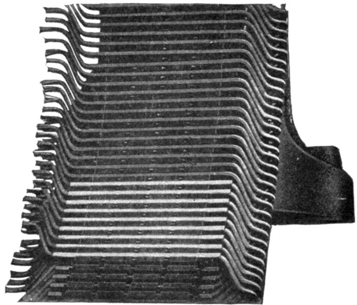
Fig. 1505.—Allis-Chalmers armature construction; view showing section of frame and two layer winding.
In practice, the coils are often more or less distributed, that is, they do not always subtend an exact pole pitch; moreover, the flux distribution, which depends on the shaping and breadth of the poles, is often quite different from a sine distribution. Hence, the coefficient 2.22 in equation (2) is often departed from, and in the general case equation (2) may be written
kfZN
Evirt = (3)
108
where k is a number which may have different values, according to the construction of the alternator. This number k is called the Kapp coefficient because its significance was first pointed out by Prof. Gisbert Kapp.
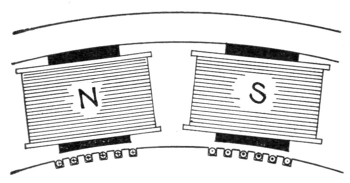
Figs. 1,506 and 1,507.—Effect of breadth of coils in distributed windings. In the section of the alternator shown in fig. 1,506 the directions of the pressures induced as the armature rotates clockwise are represented by dots for those which act towards the reader, and by crosses for those which act from the reader (the dots and crosses representing respectively the heads and tails of arrows). Since the field is not uniform but maximum at the center and gradually weakening towards the extremities, it is obvious that the maximum pressure is induced in any inductor as it passes the center of the pole, this variation being indicated by the heavier dots and crosses toward the center. Now if a number of these inductors be connected up to form a distributed coil as in fig. 1,507, the pressures induced in each will be added, but all the maximum pressure will not be induced in all at the same time, hence the total pressure induced in the distributed coil is less than it would be if the coil were concentrated as in fig. 1,509.
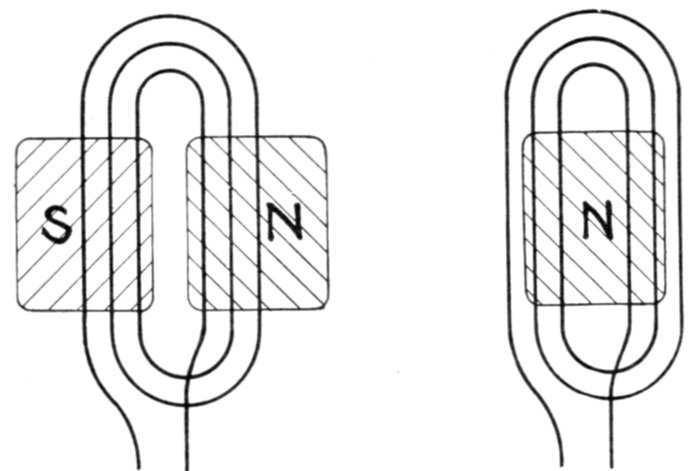
Fig. 1,508.—Diagram of distributed coil whose inner breadth is less than the breadth of the pole face, showing the disadvantage of such arrangement. The pressures induced in the inner windings of such a coil are opposing each other at the instant depicted, that is, while the inductors are under the pole face, such action of course being objectionable.
The value of k is further influenced by a "breadth coefficient" or "winding factor."
The effect of breadth in distributed windings is illustrated in figs. 1,506 to 1,508.
Wire, Strap, and Bar Windings.—In the construction of alternators, the windings may be of either wire, strap, or bar, according to which is best suited for the conditions to be met.
Ques. What conditions principally govern the type of inductor?
Ans. It depends chiefly upon the current to be carried and the space in which the inductor is to be placed.
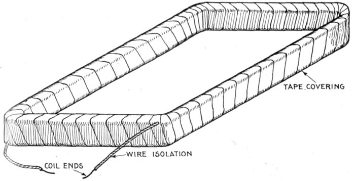
Fig. 1,509.—Simple form of alternator coil, consisting of numerous turns of insulated wire wound around a form, then covered with a tape winding, varnished and baked.
Ques. What kind of inductors are used on machines intended for high voltage and moderate current?
Ans. The winding is composed of what is called magnet wire, with double or triple cotton insulation.
Ques. Where considerable cross section is required how is a wire inductor arranged?
Ans. In order that the coil may be flexible several small wires in multiple are used instead of a single large wire.
Ques. How is the insulation arranged on inductors of this kind?
Ans. Bare wire is used for the wires in parallel, insulation being wrapped around them as in fig. 1,510.
This construction reduces the space occupied by the wires, and the insulation serves to hold them in place.
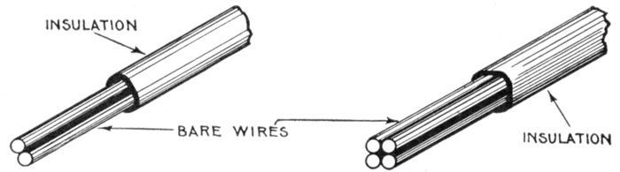
Figs. 1,510 and 1,511.—Multi-wire inductors. When the cross section of inductor necessary to carry the current is large, the use of a single wire would present difficulties in winding on account of its stiffness. Accordingly two or more smaller wires are used in parallel to secure the required cross section. Bare wire is used and the several sections encased in insulation as shown, the combination being more flexible than an equivalent single wire.
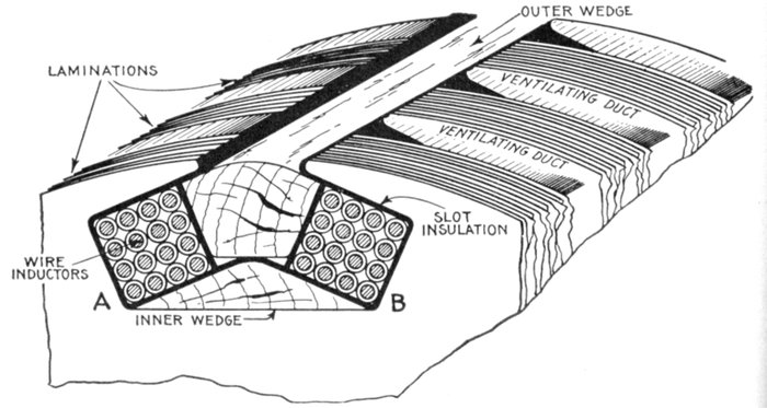
Fig. 1,512.—Two coil slot for whole coil winding. The slot has two recesses A and B for the reception of separate coils. In assembling the winding, the inner wedge is first placed in position and then the slot line with the insulating material. This usually consists of alternate layers of mica and pressboard. The coils composed of several turns of wire or copper strip are wound in place, and after covering with a layer of insulation, the outer wedge is pushed in place to retain the inductors in position.
Ques. What precaution is taken in insulating a wire wound coil containing a large number of turns?
Ans. On account of the considerable difference of pressure between layers, it is necessary to insulate each layer of turns as well as the outside of the coil, as shown in fig. 1,513.
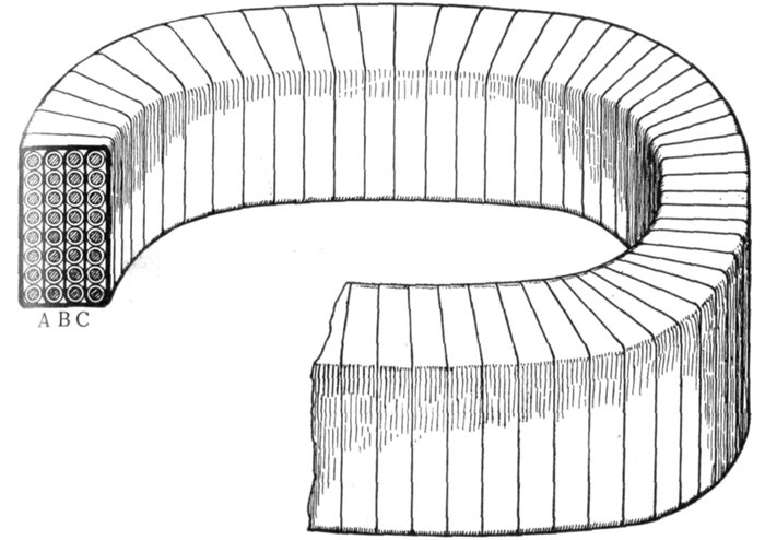
Fig. 1,513.—Method of winding a coil containing a large number of turns, when there is considerable difference of pressure between the layers. In such cases to guard against short circuits or breakdown of the insulation, each layer of turns is insulated from the next layer by the insulating strips A, B, C, in addition to the regular insulation around each wire. After the coil is made up it is wound with insulating tape, varnished and baked.
Ques. Do distributed coils require insulation between the separate layers?
Ans. Since they are subdivided into several coils insulation between layers is usually not necessary.
Ques. How is a coil covered?
Ans. It is wound with a more or less heavy wrapping of tape depending upon the voltage.
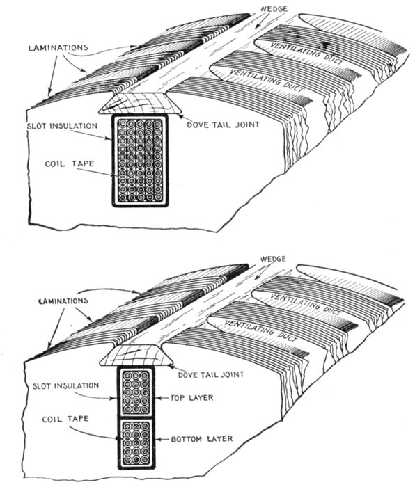
Figs. 1,514 and 1,515.—Single and double layer multi-wire inductors and methods of placing them on the core. Here the term layer means unit, in fact each unit is made up of several "layers" of wires. In fig. 1,514, where so many wires are bunched together in one unit, each layer of turns is separated from those adjacent by insulating strips on account of the considerable difference of pressure between layers. This insulation is not necessary in fig. 1,515 where there are two units or so called layers. In both cases the inductors are held in place by wedges driven into dovetail grooves.
Linen tape of good quality, treated with linseed oil, forms a desirable covering. Where extra high insulation is required the tape may be interleaved with sheet mica.
Ques. Is the insulation placed around the coils all that is necessary?
Ans. The slots into which the coils are placed, are also insulated.
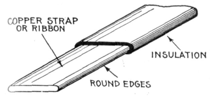
Fig. 1,516.—Copper strap or ribbon with insulation. These are generally from 1/32 to 1/16 inch thick with rounded edges as shown to avoid cutting the insulation.
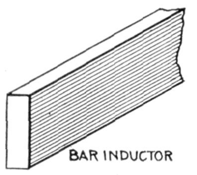
Fig. 1,517.—Bar inductor. Its shape enables putting the maximum cross section of copper into the slot and is used to advantage on machines which generate large currents.
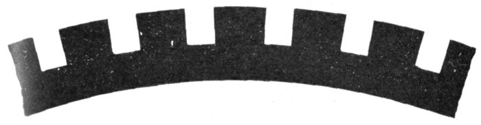
Fig. 1,518.—Style of armature core stamping used with bar wound machines. This construction, since there are no indentations in the teeth for wedges, makes it necessary to provide bands to hold the bars in place.
Ques. How are bar windings sometimes arranged?
Ans. In two layers, as in fig. 1,523.
Single and Multi-Slot Windings.—These classifications correspond to concentrated and distributed windings, previously described. In usual modern practice, only two-thirds of the total number of slots (assuming the spacing to be uniform)
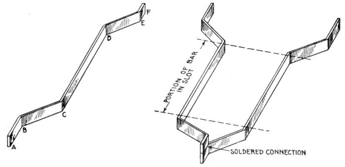
Figs. 1,519 and 1,520.—Bent bar inductor and method of connection with soldered joint. Fig. 1,519 shows one bar and shape of bent ends. The portion from C to D is placed in the slot; B to C and D to E, bent or connector sections; A to B and E to F, ends bent parallel to slot for soldering. Fig. 1,520 shows two bar inductors connected.
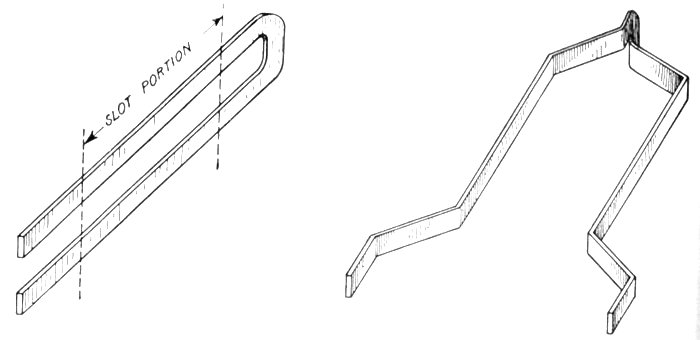
Figs. 1,521 and 1,522.—Method of avoiding a soldered joint at one end of a bar inductor by using a bar of twice the length shown in fig. 1,519, and bending it into a long U form, as in fig. 1,521, after which it is spread out forming two inductors, as in fig. 1,522.
of a single phase armature are wound with coils. The reason for this may be explained by aid of fig. 1,524, which shows an armature with six slots per pole, four of which are wound. Owing to the different positions of, say, coils A and B, there will be a difference in phase between the pressure generated in them and consequently the resultant pressure of the two coils joined in series will be less than the sum of the pressure in each coil.
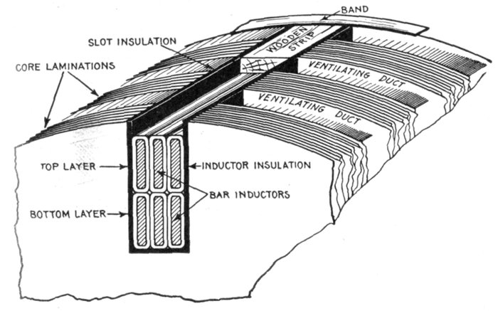
Fig. 1,523.—Arrangement in slot of two layer bar winding. With bar inductors, as must be evident from the illustration, the maximum cross section of copper can be placed in a slot of given dimension, hence a bar winding is used to advantage for alternators designed to carry a large current. Bar inductors, on account of the shape of their ends, must be placed in the slots from the top, because the bent ends do not admit of pushing them in. Straight slots are therefore necessary, the inductors being held in place by wooden strips and tie bands as shown.
Fig. 1,525 shows the pressure plotted out as vector quantities, and the table which follows gives the relative effectiveness of windings with various numbers of slots wound in series.
The figures in the last column of the table show that a large increase in the weight of active material is required if the inductors in a single phase machine are to be distributed over more than two-thirds the pole pitch. Again, if much less than two-thirds of the surface be wound, it is more difficult to provide a sine wave of pressure.
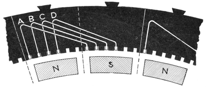
Fig. 1,524.—Diagram of single phase multi-coil or distributed winding to show characteristic differences in action and construction from single coil or concentrated winding.
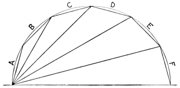
Fig. 1,525.—Vector diagram of pressures induced in the single phase multi-coil or distributed winding shown in diagram in fig. 1,524.
TABLE OF RELATIVE EFFECTIVENESS OF WINDINGS
Slots wound in series Pressure across coils Winding coefficient Quantity of copper to produce same pressure
1 1 1 1
2 1.93 .97 1.03
3 2.73 .91 1.10
4 3.34 .84 1.19
5 3.72 .74 1.35
6 3.86 .64 1.56
Ques. What other advantage besides obtaining a sine wave is secured by distributing a coil?
Ans. There is less heating because of the better ventilation.
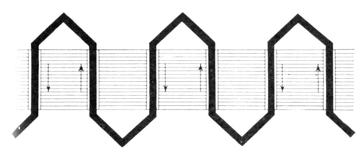
Fig. 1,526.—Developed diagram of a single phase monotooth or one slot bar winding; it is suitable only for operation at low voltage.
Single Phase Windings.—There are various kinds of single phase winding, such as, concentrated, distributed, hemitropic, etc. Fig. 1,527 shows the simple type of single phase winding. It is a "one slot" winding, that is, concentrated coils are used.
The armature has the same number of teeth as there are poles, the concentrated coils being arranged as shown. In designing such a winding, the machine, for example, may be required to generate, say, 3,000 volts, frequency 45, revolutions 900 per minute.
These conditions require 720 inductors in series in the armature circuit, and as the armature is divided into six slots corresponding to the six poles, there will be 120 inductors per slot, and the coil surrounding each of the six teeth on the surface of the armature will consist of 60 turns. The connections must be such as to give alternate clockwise and counter-clockwise winding proceeding around the armature.
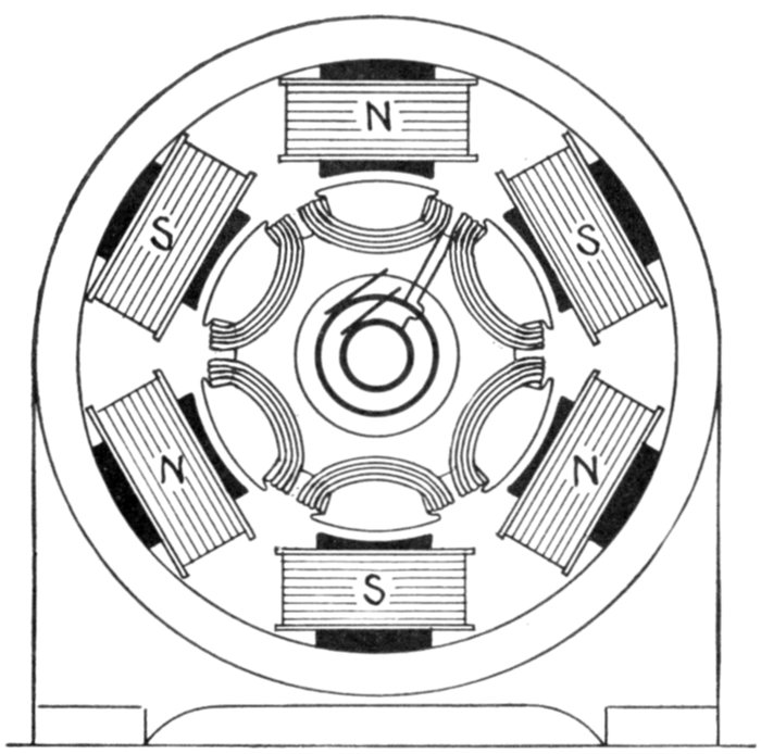
Fig. 1,527.—Diagram of six pole single phase revolving armature alternator, with monotooth or concentrated whole coil winding. For 3,000 volts at 900 revolutions per minute, 120 inductors are required. And in the case of a concentrated or monotooth winding they may be arranged in "whole coils" as above or in "half coils" (hemitropic) as in fig. 1,528.
Ques. In what other way could the inductors be arranged in concentrated coils?
Ans. They could be grouped in three coils of 120 turns each, as shown in fig. 1,528.
When thus grouped the arrangement is called a hemitropic winding, as previously explained.
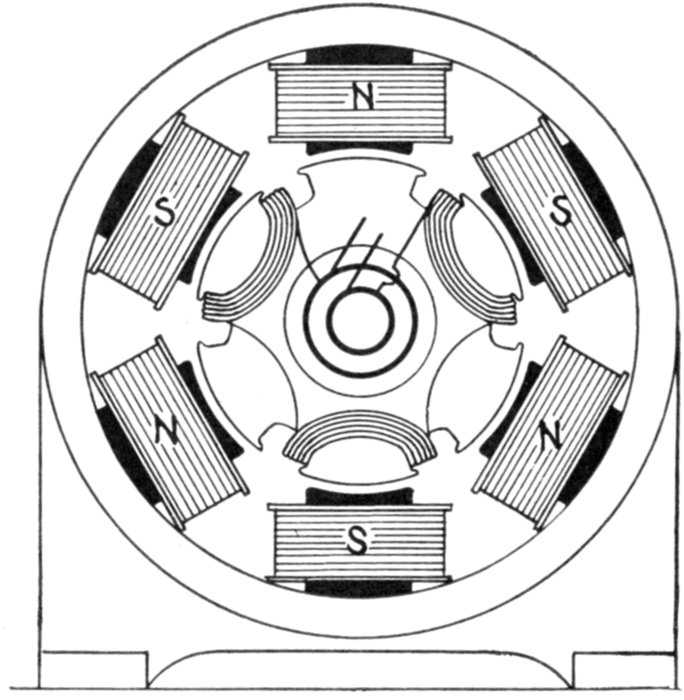
Fig. 1,528.—Diagram of six pole single phase alternator with concentrated half coil or hemitropic winding of same capacity as in fig. 1,527. There are an equal number of inductors, but in this case arranged in three instead of six coils. In this winding the direction of winding is alternately reversed so that the induced pressures do not oppose one another.
Ques. What is the advantage, if any, of a half coil winding?
Ans. In single phase machines a half coil winding is equivalent, electrically, to a monotooth winding, and, therefore, is not of any particular advantage; but in three phase machines, it has a decided advantage, as in such, a concentrated winding yields a higher pressure than a distributed winding.
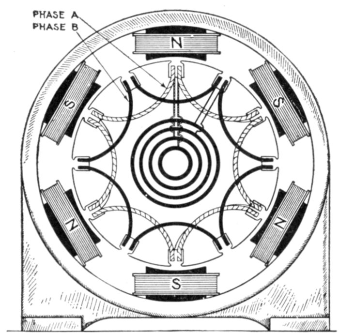
Fig. 1,529.—Two phase concentrated whole coil winding. In this style winding the total number of slots is twice the number of poles, or one slot per pole per phase. It comprises two windings identical with fig. 1,527, being spaced 90 polar degrees as shown. The two circuits are independent, the windings terminating at the four collector rings.
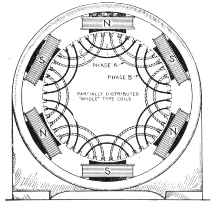
Fig. 1,530.—Two phase winding in two slots per pole per phase. This stamping distributes the coils of each phase into two sections, as A and B. The coils are of the "whole" type and with six poles the total number of slots is 4 × 6 = 24, uniformly spaced as shown.
Two Phase Armature Windings.—This type of winding can be made from any single phase winding by providing another set of slots displaced along the surface of the armature to the extent of one-half the pole pitch, placing therein a duplicate winding.
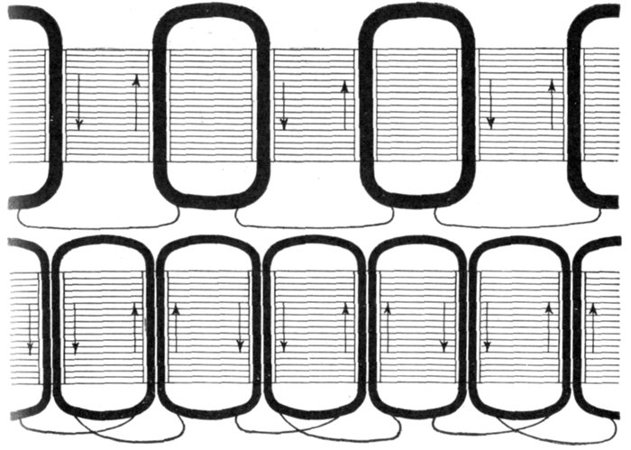
Figs. 1,531 and 1,532.—Developed diagram of the single phase monotooth windings shown in figs. 1,527 and 1,528.
For instance: If the six pole monotooth, single phase winding, shown in fig. 1,527, be thus duplicated, the result will be the one slot two-phase winding shown in fig. 1,529, which will have twelve slots, and will require four slip rings, or two rings for each phase.
By connecting up the two windings in series, the machines could be used as a single phase, with an increase of voltage in the ratio of 1.41 to 1.
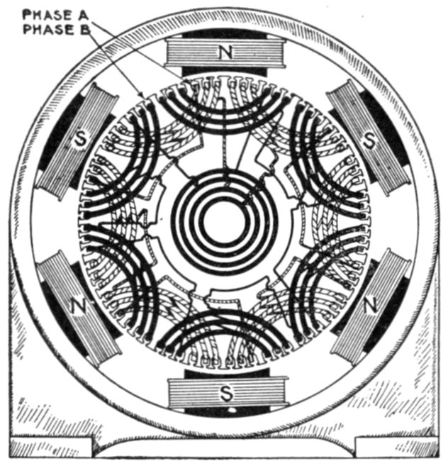
Fig. 1,533.—Two phase winding in three slots per pole per phase. The coils of each phase are of the partially distributed type, each coil being made up of three sections as shown. The direction of winding is alternately reversed.
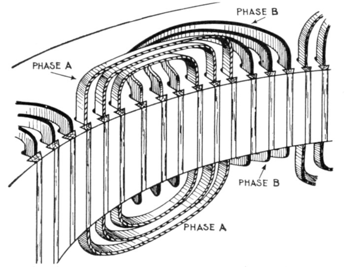
Fig. 1,534.—Section of two phase winding showing shaping of the coil ends. Every other coil is flat, while the alternates have their ends bent down as shown. With respect to the shaping of the coil ends, it is called a two range winding.
Ques. How must the coils be constructed for two phase windings?
Ans. They must be made of two different shapes, one bent up out of the way of the other, as in fig. 1,534.
There are numerous kinds of two phase windings; the coils may be concentrated or distributed, half coil or whole coil, etc. Fig. 1,530 shows a two phase winding with four slots per pole, and fig. 1,533 one with six slots per pole.
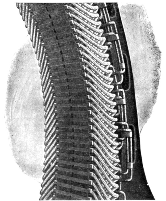
Fig. 1,535.—Section of Triumph armature showing method of arranging the three phase winding.
Three Phase Armature Windings.—On the same general principle applicable to two phase windings, a three phase winding can be made from any single phase winding, by placing three identical single phase windings spaced out successively along the surface of the armature at intervals equal to one-third and two-thirds, respectively, of the double pole pitch, the unit in terms of which the spacing is expressed, being that pitch, which corresponds to one whole period.
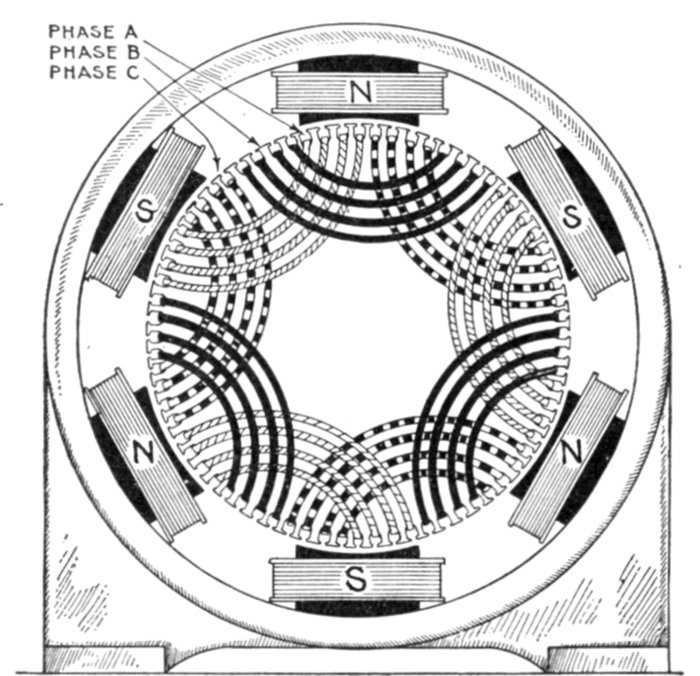
Fig. 1,536.—Three phase winding with distributed coils—wound in four slots per pole per phase; diagram showing placement of the coils.
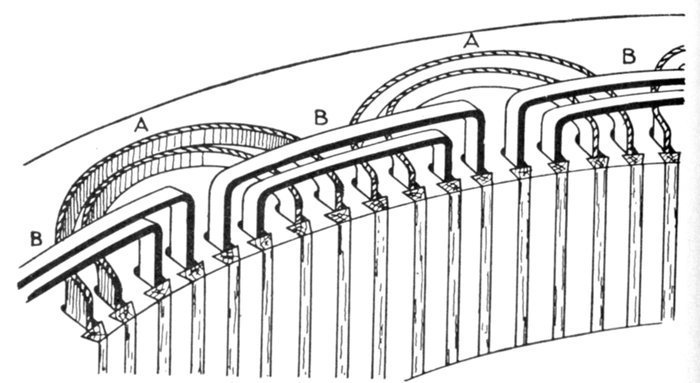
Fig. 1,537.—Treatment of coil ends in two phase, two range windings. In this arrangement straight out (B) and bent up (A) coils are used which are placed on the armature as is clearly shown in the illustration.
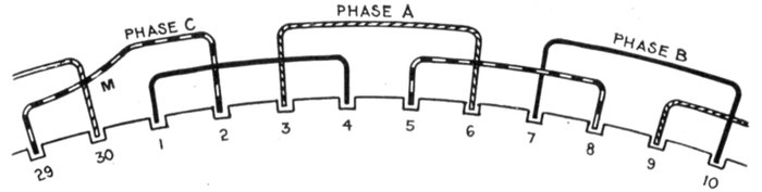
Fig. 1,538.—Three phase, 10 pole, 30 slot winding in two ranges. In this winding perfect symmetry occurs after every four poles. Accordingly in the case of an odd number of pairs of pole, one of the coils must necessarily be askew going from the inner to the outer range as at M.
Each of the three individual windings must be concentrated into narrow belts so as to leave sufficient space for the other windings between them. This limits the breadth or space occupied by the winding of any one phase to one-third of the pole pitch.
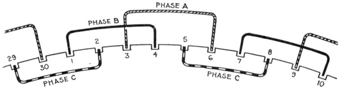
Fig. 1,539.—Three phase 10 pole 30 slot winding in three ranges. The coils of each phase are alike, those of the A phase being all in the straight out range, those in the B phase, in a bent up range, and those in the C phase in a bent down range. This arrangement has the disadvantage, that by reason of the third range, the field magnet cannot be withdrawn. This treatment of the coil ends is more clearly shown in fig. 1,540.
Ques. How are three phase coil ends treated?
Ans. They may be arranged in two ranges, as in fig. 1,538, or in three ranges, as in fig. 1,539.
Ques. What kind of coil must be used for three phase windings in order that the ends may be arranged in only two ranges?
Ans. Hemitropic or half coils; that is, the number of coil per phase must be equal to one-half the number of pole.
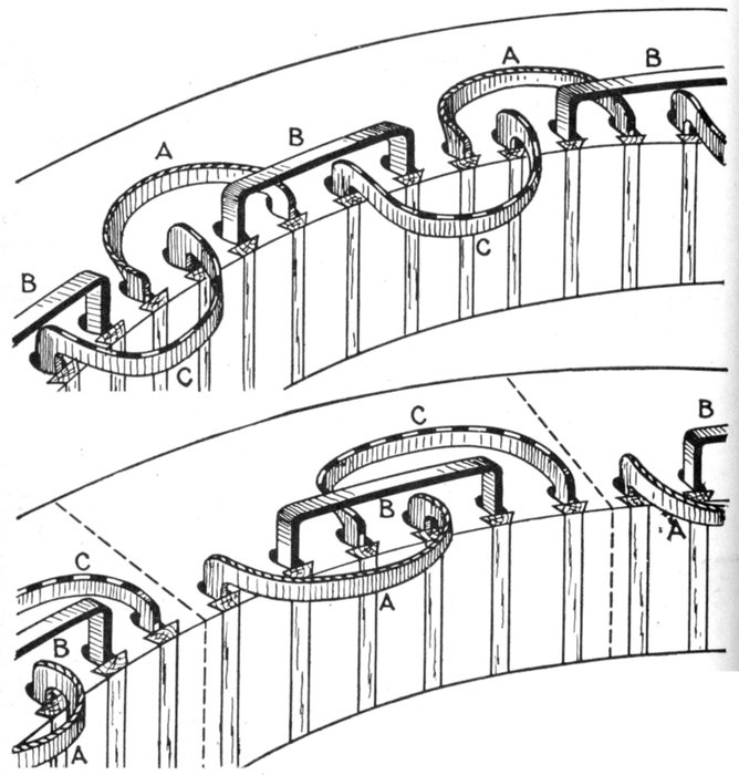
Figs. 1,540 and 1,541.—Treatment of coil ends in three phase, three range windings. Fig. 1,540, inadmissible arrangement in which the field magnet cannot be withdrawn; fig. 1,541, admissible arrangement in which the armature segments can be divided. This enables the top half of armature to be removed by disconnection without unwinding any coil.
Grouping of Phases.—In the preceding diagrams, the general arrangement of the coils on the armature surface are shown for the numerous classes of winding. In polyphase alternators the separate windings of the various phases may be grouped in two ways:
1. Star connection;
2. Mesh connection.
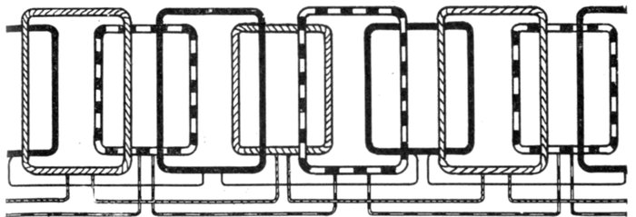
Fig. 1,542.—Three phase winding with half coils. The advantage of employing half coils is that the ends may be arranged in two ranges as shown. There is one slot per phase per pole, that is, total number of slots = 3 × number of poles.
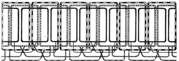
Fig. 1,543.—Three phase winding with whole coils. Two sides of adjacent coils come in one slot. Number of coils per phase = number of poles per phase. Total number of slots = 3 multiplied by number of poles per phase. Whole coils require the ends arranged in three ranges as indicated. The coils are concentrated.
Ques. Describe the two phase star connection.
Ans. In this method of grouping, the middle points of each of the two phases are united to a common junction M, and the four ends are brought out to four terminals a, a', b, b', as shown in fig. 1,544, or in the case of revolving armatures, to four slip rings.
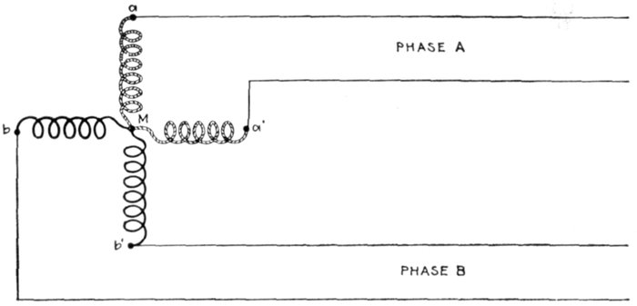
Fig. 1,544.—Diagram of two phase star grouping.
Ques. What does this arrangement give?
Ans. It is practically equivalent to a four phase system.
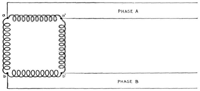
Fig. 1,545.—Diagram of two phase mesh grouping.
Ques. How is the two phase mesh connection arranged?
Ans. In this style of grouping, the two phases are divided into two parts, and the four parts are connected up in cyclic order, the end of one to the beginning of the next, so as to form a square, the four corners of which are connected to the four terminals a, b, a', b', as shown in fig. 1,545, or in the case of revolving armatures, to four slip rings.
Ques. Describe a three phase star connection?
Ans. In three phase star grouping, one end of each of the three circuits is brought to a common junction M, usually insulated, and the three other ends are connected to three terminals a, b, c, as shown in fig. 1,546, or in the case of revolving armatures to three slip rings.
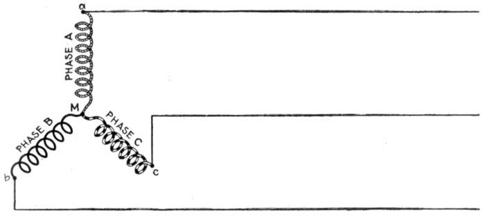
Fig. 1,546.—Diagram of three phase star grouping, commonly called Y grouping owing to its resemblance of the letter Y. The current in each main is obviously equal to the current in each phase winding, but the terminal pressure is the vector sum of the pressures in the component phase windings, that is, √3 multiplied by the pressure in one phase.
Ques. What other name is given to this connection, and why?
Ans. It is commonly called a Y connection or grouping owing to the resemblance of its diagrammatic representation to the letter Y.
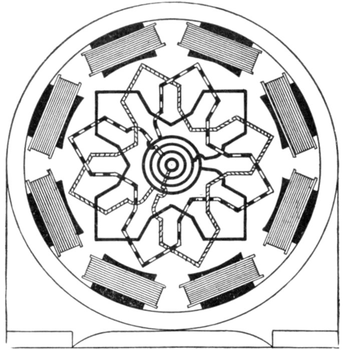
Fig. 1,547.—Radial diagram of three phase, one slot winding with Y connection.
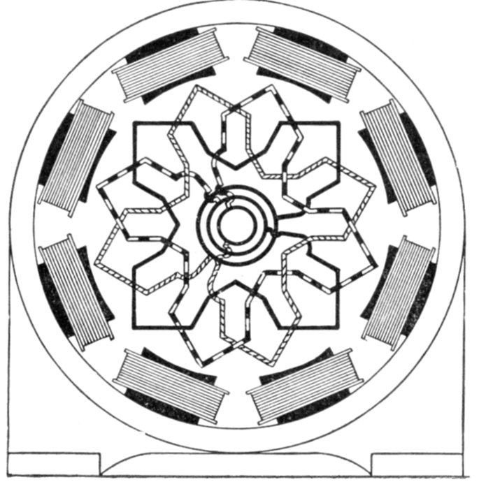
Fig. 1,548.—Radial diagram of three phase one slot winding with delta connection.
Ques. How is a three phase mesh connection arranged?
Ans. The three circuits are connected up together in the form of a triangle, the three corners are connected to the three terminals, a, b, c, as shown in fig. 1,549, or in the case of revolving armatures to three slip rings.
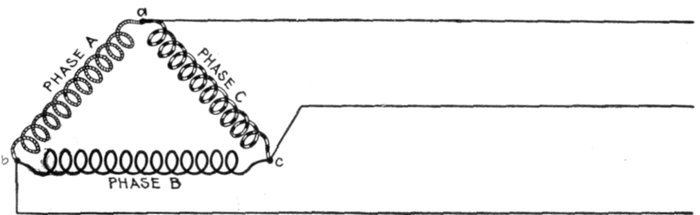
Fig. 1,549.—Diagram of three phase mesh grouping, commonly called delta grouping owing to its resemblance to the Greek letter Δ. The voltage at the terminals is equal to the voltage in one phase, and the current in each line is equal to the vector sum of the currents in two phases, that is, it is equal to √3 multiplied by the current in one phase.
Ques. What other name is given to this style of connection, and why?
Ans. It is commonly called a delta grouping on account of the resemblance of its diagrammatic representation to the Greek letter Δ.
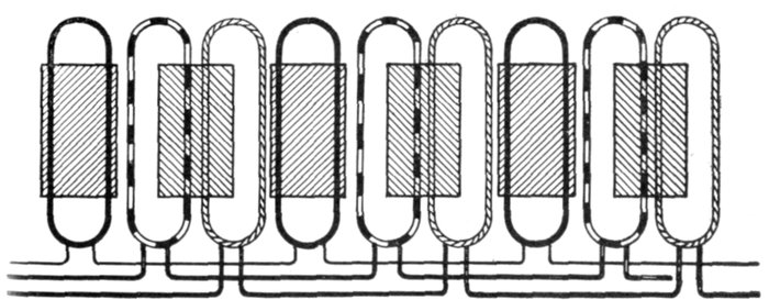
Fig. 1,550.—Three phase winding with short coils. The use of short coils as here shown, in which the coil breadth = ⅔ pole pitch, avoids the necessity of overlapping.
In polyphase working, it is evident that by the use of four equal independent windings on the armature, connected to eight terminals or slip rings, a two phase alternator can be built to supply currents of equal voltage to four independent circuits. Likewise, by the use of three equal independent windings, connected to six terminals or slip rings, a three phase alternator can be made to supply three independent circuits.
This is not the usual method employed in either case, however, as the star grouping or mesh grouping methods of connection not only gives the same results, but also, in star grouping, a greater plurality of voltages for the same machine, and a higher voltage between its main terminals.
Radial diagrams of the arrangement and connections of Y grouping of lap windings and wave windings for three phase alternators are shown by figs. 1,551 and 1,552.
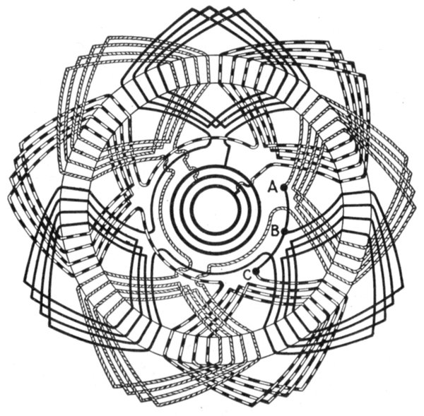
Fig. 1,551.—Radial diagram of three phase lap winding with star connection.
Ques. In three phase star grouping, what is the point where the phases join, called?
Ans. The star point.
Ques. In a three phase star connected alternator what is the voltage between any two collector rings?
Ans. It is equal to the voltage generated per phase multiplied by √3 or 1.732.
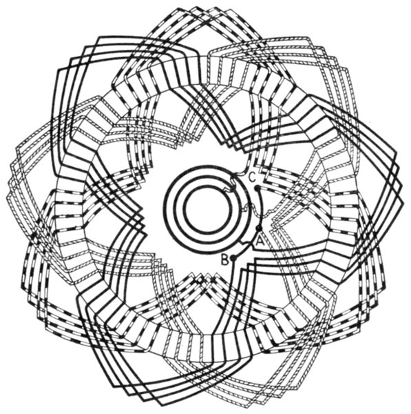
Fig. 1,552.—Radial diagram of three phase wave winding with star connection.
Ques. In a three phase star connected alternator what is the value of the current in each line?
Ans. The same as the current in each phase winding.
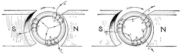
Figs. 1,553 and 1,554.—Gramme ring armatures showing three phase star and mesh connections, respectively, with direction of currents in the coils. In the figures, the coils A, B, C, are spaced at equidistant positions on the ring core. The arrow heads represent the directions of the induced pressures or currents for the position shown, the rotation being clockwise. In coil A the pressure is increasing, in coil B it is diminishing, but is in the same direction as in A, whereas in coil C it is also diminishing, but is in the opposite direction to what it is in coils A and B. As the rings rotate the three coils have similar alternations of pressure induced in them, but differ in phase. If a, b and c be joined to collector rings three phase currents can be supplied to the outer circuits. In fig. 1,553 at the instant represented a and b are giving their current to their lines, while c is receiving from its line a current equal to the sum of a and b. In fig. 1,554, at the instant represented, the currents sent out from a will be equal to the sum of the currents in x and y, and intermediate between them in phase. The current from b will be equal to the difference of the currents in z and y, and of intermediate phase, while similarly the current received by c will be equal to the sum of the currents in x and z.
Ques. What is the value of the total output in watts of a star connected alternator?
Ans. It is equal to the sum of the outputs of each of the three phases. When working on a non-inductive load, the total output of a star connected alternator is equal to √3 multiplied by the product of the line current and line voltage.
Ques. What is the value of the line voltage in a three phase delta connected alternator?
Ans. It is equal to the voltage generated in each phase.
Ques. What is the value of the line current in a three phase delta connected alternator?
Ans. It is equal to the current in each phase multiplied by √3.
Ques. What is the total output of a three phase delta connected alternator working on a non-inductive load?
Ans. The total watts is equal to √3 multiplied by the product of the line current and the line voltage.
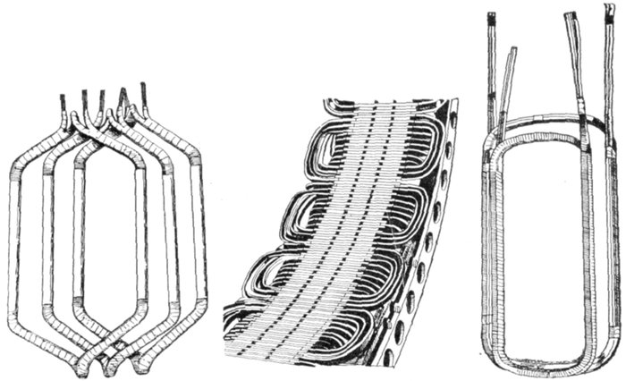
Figs. 1,555 to 1,557.—Separate coils, and section of Allis-Chalmers alternator with coils in place. Numerous openings are provided in the frame through which air currents, set up by the revolving field, can pass freely and carry off heat. Shields are provided to protect the armature coils where they project beyond the core. In assembling the core spacing segments are placed at intervals to form ventilating ducts. After the coils have been covered with insulating materials and treated with insulating compound, the parts that are to lie in the slots are pressed to exact size in steam heated moulds. This runs the insulating material into all the small spaces in the coil so as to exclude moisture, it also makes the coil structure firm and solid. The projecting ends of the coils are heavily taped, suitable supports being provided for the coil connections so that they cannot become displaced on account of stresses due to short circuits or other causes. On high pressure machines the armature terminals are arranged so that it is impossible for an attendant to make accidental contact with them.
Ques. What are the features of the star connection?
Ans. It gives a higher line voltage than the delta connection for the same pressure generated per phase, hence it is suited for machines of high voltage and moderate current.
The delta connection gives a lower line voltage than the star[5] connection for the pressure generated per phase, and cuts down the current in the inductors; since the inductors, on this account, may be reduced in size, the delta connection is adapted to machines of large current output.
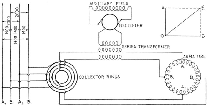
Fig. 1,558.—Diagram of Westinghouse two phase composite wound alternator, showing connections between two phase armature and a single phase rectified and composite field winding. The arrangement makes use of a series transformer, mounted on the spokes of the armature. By means of this series transformer the voltage delivered to the rectifying commutator and the fields is much less than that generated by the machine. The armature of this machine is of the closed coil single winding type, all the armature inductors being connected with each other to form a closed circuit which resembles to a certain extent the ordinary drum winding of a multipolar direct current machine. This winding is tapped out at two points per pole just as is the continuous winding of a two phase rotary converter, these taps running to collector rings through which the currents are delivered to the outside circuits. On account of this connection of both phases to one winding there is a definite voltage set up between the inductors of phase A, and of phase B, this voltage being shown by the figures given in the diagram. The arrangement is adapted for two phase work by fitting the series transformer for the auxiliary field excitation with two primaries connected respectively in one leg of each of the two phases; thus the transformer is excited by two currents normally ¼ period out of phase with each other. The result upon the secondary is a combination of the effects of the two primary currents, the voltage delivered by the secondary being intermediate in phase between those pressures which would be separately set up by the two primaries. This combination effect is shown in the small diagram in the upper right hand corner of the illustration. If OA be the effect set up in the secondary of the series transformer by the primary current of phase A, and OB be the effect set up by the primary current of phase B, OC represents in magnitude and phase relation the resultant effect upon the secondary. It is readily seen that this resultant is not equal to the arithmetical sum of the two components since, to a certain extent, they work at cross purposes. However, if either one of them increase the resultant effect increases, although not in exact proportion. If the load remain balanced, the two components remaining equal to each other, the resultant OC varies in exact proportion to any changes in the components. If the load become unbalanced, the resultant swings around more nearly into phase with the larger load; thus if OB become greater, OA remaining the same, OC swings around, becoming more nearly horizontal. This requires a readjustment of the position of the brushes on the commutator to set them properly for minimum sparking, an adjustment exactly similar to that required when the power factor of the load changes.
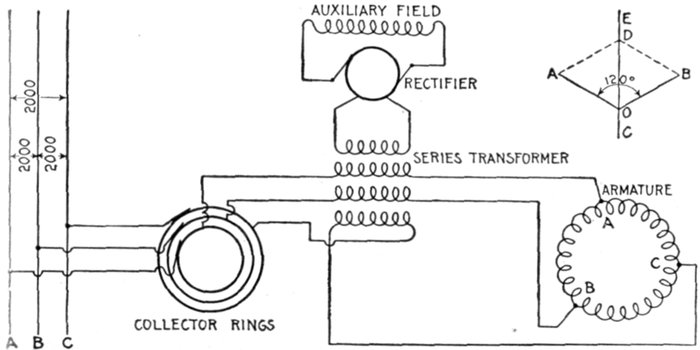
Fig. 1,559.—Diagram of Westinghouse three phase composite wound alternator. The armature inductors are of the closed coil or delta connected type, but are tapped at three points per pair or poles to the three collector rings. All three connections between the armature coils and the collector rings run through primary circuits of the series transformer within the armature, these three primaries each giving their own effect upon the secondary. Since the resultant of three equal alternating electromotive forces 120° apart is zero, so that some special arrangement must be adopted to make these electromotive forces act with instead of against each other. The arrangement is a reversal of the connections of one of the primaries of the series transformer. This is shown in the case of the lowest primary indicated in the diagram. The combination of the effects of the three primaries is again indicated in the small vector diagram in the upper right hand corner. Here OA is the effect of one primary, OB that of another ⅓ of a period displaced from the former in phase, and OC that which the third would exert were it not reversed, but the reversal brings the effect of this third coil into the phase relation OD, so that the three are only 60° apart. The combination of OA and OB is equal to OC, which combined again with OD gives a resultant effect, OE. In this case, as in the other, the effect upon the series field does not remain exactly proportional to the load unless the latter is balanced; in fact, an increased current through the one leg represented by OD, affects the series field as much as an equal increase in each of the other legs put together. Practically, however, any increase of the load—distributed as it must be in two legs at least—increases the field excitation so that proper regulation is secured.
Ques. How is the path and value of currents in a delta connected armature determined?
Ans. Starting with the inductors of one phase opposite the middle of the poles, assume the maximum current to be induced at this moment; then but one-half of the same value of current will be induced at the same moment in the other two phases, and its path and value will best be shown by aid of fig. 1,560, in which X may be taken as the middle collector ring, and the maximum current to be flowing from X toward Z. It will be seen that no current is coming in through the line Y, but part of the current at Z will have been induced in the branches b and c.
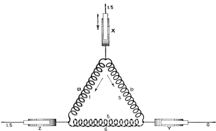
Fig. 1,560.—Diagram showing determination of path and value of current flowing in delta connected armature.
Ques. Since most three phase windings can be connected either Y or delta, what should be noted as to the effects produced?
Ans. With the same winding, the delta connection will stand 1.732 as much current as the Y connection, but will give only 1 ÷ 1.732 or .577 as much voltage.
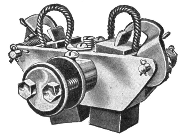
Fig. 1,561.—Triumph brushes and brush holder. The holder is of the box type provided with an adjustable tension spring, making the brushes self-feeding. Each holder is carried on insulated studs attached to a cast iron yoke which is mounted on the bearing.
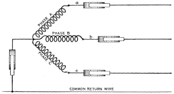
Fig. 1,562.—Diagram of Y connection with a common return wire. When the three lines leading from a, b and c are equal in resistance and reactance, or in other words when the system is balanced, the currents of the three phases are equal and are 120° apart in phase (each current lagging behind its pressure by the same amount as the others) and their sum is at each instant equal to zero. In this case the resultant current being equal to zero there is no need of a common return wire. However, in some cases, where power is distributed from transformers or three wire systems, the different branches are liable to become unbalanced. Under such circumstances the common return wire is sometimes used, being made large enough to take care of the maximum unbalancing that may occur in operation. The return wire is used sometimes on alternators that furnish current mostly for lighting work.
Chain or Basket Winding.—One disadvantage in ordinary two-range windings is that two or three separate shapes of coil are required. The cost of making, winding, and supplying spares would be less if one shape of coil could be made to do for all phases. One way of accomplishing this is by the method of chain winding, in which the two sides of each coil are made of different lengths, as shown in fig. 1,563, and bent so that they can lie behind one another.
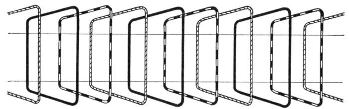
Fig. 1,563.—Diagram showing chain winding. In this method of winding the coils are all similar with long and short sides. It obviates the extra cost of making coils of several different shapes. The diagram represents a winding for one slot per pole per phase.
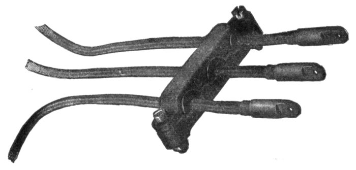
Fig. 1,564.—General Electric terminal board showing cables leading to three phase winding.
In the case of open slots the coils may be former wound and afterwards wedged into their places.
In chain winding the adjacent coils link one another as in a chain (hence, the name); the winding is similar to a skew coil winding. This plan of winding is supposed to have some advantage in keeping coils of different phases further separated than the two range plan.
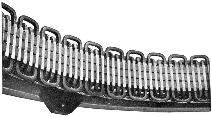
Fig. 1,565.—Section of armature winding of Allis-Chalmers 500 kw. three phase water wheel alternator. The coils are of the concentrated "half" type. Each coil is completely insulated before being placed on the core and no insulation is placed in the slot itself. The ends of the coils where they project beyond the slots are heavily taped. Where necessary suitable supports are provided for the coil connections so that they cannot become displaced on account of stresses due to short circuits or other causes. The winding is of the "chain" type. This is shown by the way the coils are connected together at the right. The armature terminals are either provided with insulated connectors or are led to a marble terminal board on which the terminals are so mounted and protected that it is impossible for an attendant to make accidental contact with them. The position of the illustration would indicate a horizontal alternator but the machine is of the vertical type; the lug on the right shows this, being used for adjusting the alternator on the foundation.
Skew Coil Winding.—In this type of winding the object is to shape the coils so that all may be of one pattern. This is accomplished by making the ends skew shape as shown in figs. 1,566 to 1,568.
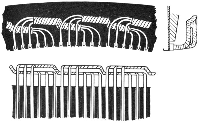
Figs. 1,566 to 1,568.—Views of a section of skew coil winding; so called on account of the skew shape given to the coil ends in order that all the coils may be of one shape.
Fed-in Winding.—This name is given to a type of winding possible with open or only partially closed slots, in which coils previously formed are introduced, only a few inductors at a time if necessary. They are inserted into the slots from the top, the slot being provided with a lining of horn fibre or other suitable material, which is finally closed over and secured in place by means of a wedge, or by some other suitable means. An example of a fed-in winding is shown in figs. 1,566 and 1,568.
Imbricated Winding.—This is a species of spiral coil winding in which the end connections are built up one above the other, either in a radial, or in a horizontal direction.
The winding is used especially on the armatures of turbine alternators and dynamos.
Spiral Winding.—This is a winding in which "spiral" coils, as shown in fig. 1,569, are used. The spiral form of coil is very extensively used for armature windings of alternators.
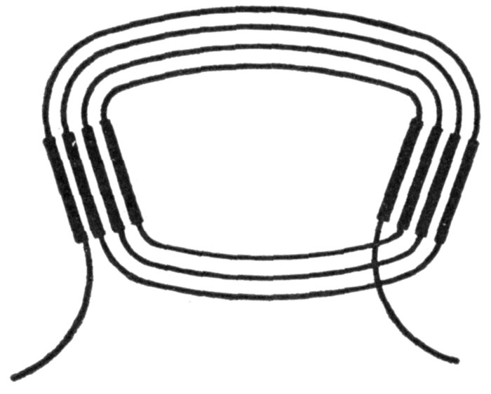
Fig. 1,569.—Diagram showing a spiral coil. This type of coil is one in which each successive turn lies entirely within the previous turn, starting with the outermost turn of the coil. The successive turns of a spiral coil are thus not of the same size, and are not overlapping as in a "lap" coil.
Mummified Winding.—The word mummified as applied to a winding is used to express the treatment the coils of the winding receive in the making; that is, when a winding, after being covered with tape or other absorbent material, is saturated in an insulating compound and baked until the whole is solidified, it is said to be mummified.
Shuttle Winding.—This type of winding consists of a single coil having a large number of turns, wound in two slots spaced 180° apart. It was originally used on Siemens' armature and is now used on magnetos, as shown in figs. 1,459 to 1,461.
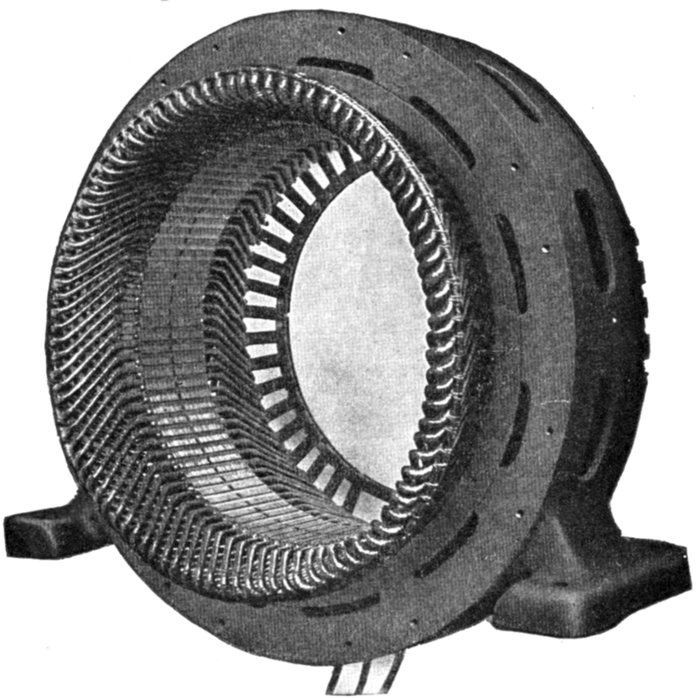
Fig. 1,570.—Frame and armature winding of Westinghouse pedestal bearing alternator. Armature frames are of cast iron and ventilated. Interior transverse ribs strengthen the frame and support the core laminations. The armature core is built up of annealed and japanned punched laminations. Armature slots are open. Armature coils are form wound, impregnated, and interchangeable; they are held in place with fiber wedges. Ventilating spaces are provided at intervals in the armature core and also between all coil ends.
Creeping Winding.—Another species of winding, known as a creeping winding is applicable to particular cases.
If three adjacent coils, each having a pitch of 120 electrical degrees, be set side by side, they will occupy the same breadth as 4 poles, and, by repetition, will serve for any machine having a multiple of 4 poles, but cannot be used for machines with 6, 10 or 14 poles. Fig. 1,571 shows this example.
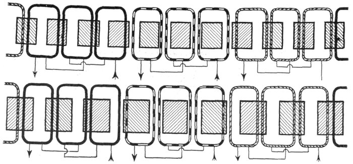
Figs. 1,571 and 1,572.—Diagram of creeping windings. Fig. 1,571, three coils subtending four poles; fig. 1,572, nine coils subtending eight poles.
In the same way 9 coils, each of 160 electrical degrees, will occupy the same angular breadth as 8 poles.
Further, 9 coils of 200 electrical degrees will occupy the same angular breadth as 10 poles.
Now of these 9 coils, any three contiguous ones are nearly in phase, if wound alternately clockwise and counter-clockwise.
For the 8 pole machine, the phase difference between adjacent coils is 20 degrees.
For the 10 pole machine, the phase difference is also 20 degrees.
The cosine of 20 degrees is .9397, consequently, if 3 adjacent coils be united in series, their joint pressure will be 2.897 multiplied by that of the middle one of the three.
The 9 coils may therefore be joined up in three groups of 3 adjacent coils, for the three phases.
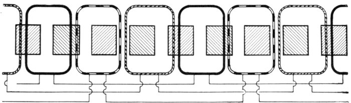
Fig. 1,573.—Developed diagram of creeping winding: nine coils subtending ten poles.
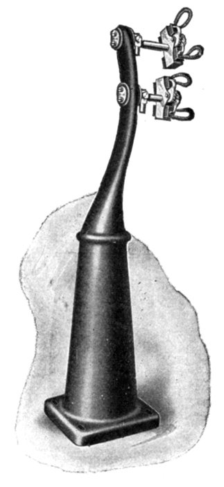
Fig. 1,574.—Triumph pedestal and brush rigging for large revolving field alternators. Carbon brushes are used, carried in box type brush holders. The stand or pedestal here shown is the kind used with the engine and fly wheel types of alternator. The brush studs are mounted on the stand in such a manner that the brushes are easily accessible. The latter carry only the low voltage direct current necessary for exciting the field.
By repetition, the same grouping will suit for any machine having a multiple of 8 or of 10 poles. These two cases are illustrated in figs. 1,572 and 1,573. In the figures, the coils are represented as occupying two slots each, but they might be further distributed.
Turbine Alternator Winding.—For the reason that steam turbines run at so much higher speed than steam engines, the construction of armatures and windings for alternators intended to be direct connected to turbines must be quite different from those driven by steam engines. Accordingly, in order that the frequency be not too high, turbine driven alternators must have very few poles—usually two or four, but rarely six.
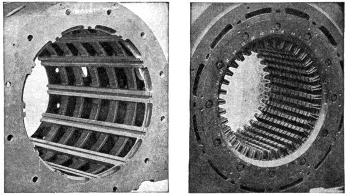
Figs. 1,575 and 1,576.—Westinghouse turbine alternator armature construction. Fig. 1,575. View showing dovetail grooves in armature casting; fig. 1,576, laminæ assembled in dovetail grooves of armature casting.
The following table will show the relation between the revolutions and frequencies for the numbers of poles just designated.
TABLE OF FREQUENCY AND REVOLUTIONS
Frequency Revolutions
2 pole 4 pole 6 pole
25 1,500 750 500
60 3,600 1,800 1,200
100 6,000 3,000 2,000
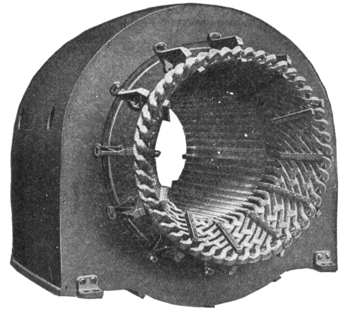
Fig. 1,577.—Armature of Westinghouse turbine alternator with end bells removed showing method of bracing the coil ends.
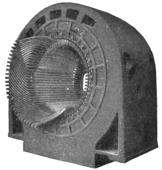
Fig. 1,578.—Stationary armature of Westinghouse turbine alternator with part of the winding in place. Because of the small number of coils in a turbine alternator as compared with a slow speed machine of the same kva. rating, each coil carries a great amount of power on large load, particularly at times of short circuits or grounds on the external circuit. The "throw" of the coils is large, leaving a considerable part of the winding in the end turns unsupported by the armature core. For these reasons great stresses, which are dangerous, if effective means be not adopted to withstand them, may exist between the coils. The inductors are of such cross section that they can be made rigid and insulated satisfactorily. The end turns are given a fan like form as shown, affording ventilation and effective bracing as shown in fig. 1,577. Cord lashings are, except in the smallest frames, used only for holding in the small spacing blocks between the coils. They are not depended on to support the coils. Malleable iron braces, hard maple blocks, and brass or steel bolts with brass washers are used to withstand the mechanical stresses imposed on the armature coils by external short circuits.
From the table, it is evident that a large number of poles is not permissible, considering the high speed at which the turbine must be run.

Fig. 1,579.—Two pole radial slot field. Radial slot fields are used on very small and very large alternators. The field diameters are so small that the end turns of the winding can be effectively bound into place, such binding being necessary with a radial slot machine. The shaft and disc are a one piece forging of steel.
Ques. How is the high voltage obtained with so few poles?
Ans. There must be either numerous inductors per slot or numerous slots per pole.
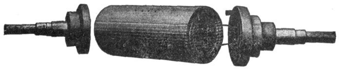
Figs. 1,580 to 1,582.—Westinghouse two pole parallel slot field with ends removed showing construction. The parallel slot design of field construction is used in Westinghouse machines up to 10,000 kva. capacity. In fig. 1,581, the large holes at the end near the circumference of the cylinder are for the accommodation of the bolts that hold the bronze end discs and stub shafts. In winding, the cylinder is mounted on a horizontal turntable that rotates in a horizontal plane. The copper strap field coil winding is wound turn by turn under pressure and strip insulation is wound in between. When completed the turns are held rigidly in position with heavy brass wedges. An end disc made of bronze holds the stub shaft and is bolted to each end of the steel center. When the leads are attached to the collector rings the field is complete.
Ques. What form of armature is generally used?
Ans. A stationary armature.
Ques. What difficulty is experienced with revolving armatures?
Ans. The centrifugal force being considerable on account of the high speed, requires specially strong construction to resist it, consequently closed or nearly closed slots must be used.
Ques. How is the design of the rotor modified so as to reduce the centrifugal force?
Ans. It is made long and of small diameter.
Some examples of revolving fields are shown in figs. 1,579 to 1,584. Figs. 1,577 and 1,578 show some construction details of a stationary armature of turbine alternator.
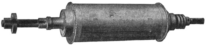
Fig. 1,583.—Westinghouse two pole parallel slot turbine alternator field.
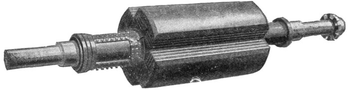
Fig. 1,584.—Westinghouse four pole parallel slot turbine alternator field.
HAWKINS PRACTICAL LIBRARY OF ELECTRICITY IN HANDY POCKET FORMPRICE $1 EACH
They are not only the best, but the cheapest work published on Electricity. Each number being complete in itself. Separate numbers sent postpaid to any address on receipt of price. They are guaranteed in every way or your money will be returned. Complete catalog of series will be mailed free on request.
ELECTRICAL GUIDE, NO. 1
Containing the principles of Elementary Electricity, Magnetism, Induction, Experiments, Dynamos, Electric Machinery.
ELECTRICAL GUIDE, NO. 2
The construction of Dynamos, Motors, Armatures, Armature Windings, Installing of Dynamos.
ELECTRICAL GUIDE, NO. 3
Electrical Instruments, Testing, Practical Management of Dynamos and Motors.
ELECTRICAL GUIDE, NO. 4
Distribution Systems, Wiring, Wiring Diagrams, Sign Flashers, Storage Batteries.
ELECTRICAL GUIDE, NO. 5
Principles of Alternating Currents and Alternators.
ELECTRICAL GUIDE, NO. 6
Alternating Current Motors, Transformers, Converters, Rectifiers.
ELECTRICAL GUIDE, NO. 7
Alternating Current Systems, Circuit Breakers, Measuring Instruments.
ELECTRICAL GUIDE, NO. 8
Alternating Current Switch Boards, Wiring, Power Stations, Installation and Operation.
ELECTRICAL GUIDE, NO. 9
Telephone, Telegraph, Wireless, Bells, Lighting, Railways.
ELECTRICAL GUIDE, NO. 10
Modern Practical Applications of Electricity and Ready Reference Index of the 10 Numbers.
Theo. Audel & Co., Publishers.
72 FIFTH AVENUE, NEW YORK