Chapter XX · COMMUTATION AND THE COMMUTATOR
Reading edition
The act of commutation needs special study. If it be incorrectly performed, the imperfection at once manifests itself by sparks which appear at the brushes. In the study of this chapter on commutation it would be advisable for the student to first review the basic principles of commutation as given in chapter XIV, which contains a brief and simple explanation of how the alternating current in the armature is converted into direct current by the action of the commutator.
Ques. What is the period of commutation?
Ans. The time required for commutation, or the angle through which the armature must turn to commute the current in one coil.
Ques. Upon what does the period of commutation depend?
Ans. Upon the width of the brushes as shown in fig. 300.
This fixes the angle through which the armature must revolve to commute the current in one coil. This angle is formed, as shown in the figure, by two intersecting planes, M and S, which pass through the axis of the armature and the two edges of the brush. Commutation then, begins at M and ends at S.
Ques. What is the position of the commutating plane with respect to M and S, in fig. 300?
Ans. It bisects the angle formed by the planes M and S.
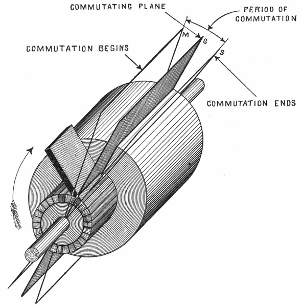
Fig. 300.—Armature with one brush in position to illustrate the period of commutation and commutating plane. The latter is called "commutating line" by some writers. The period of commutation depends on the thickness of the brush end in contact with the commutator. Careful distinction should be made between commutating plane, neutral plane, and normal neutral plane as defined elsewhere.
Ques. What is the commutating plane?
Ans. An imaginary plane passing through the axis of the armature and the center of contact of the brush.
Ques. What two planes are referred to in stating the position of the brushes?
Ans. The normal neutral plane and the commutating plane.
The angle intercepted by these two planes represents the lead, thus in stating that the brushes have a lead of 6°, means that the angle intercepted by the normal neutral plane and the commutating plane is 6°.
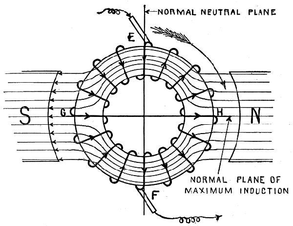
Fig. 301.—The proper position of the brushes, if there were no field distortion and self-induction in the armature coils, would be in the normal neutral plane. In the actual dynamo these two disturbing effects are present which makes it necessary to advance the brushes as shown in figs. 302 and 303 to secure sparkless commutation.
Ques. What is the difference between the normal neutral plane and the neutral plane?
Ans. This is illustrated in figs. 301 and 302. The normal neutral plane is the position of zero induction assuming no distortion of the field as in fig. 301. The neutral plane is the position of zero induction with distorted field as in fig. 302 and as is found in the actual machine; the distortion is exaggerated in the figure for clearness.
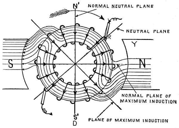
Fig. 302.—Brush adjustment for field distortion. The effect of the latter is to twist the lines of force around in the direction of rotation, thus maximum induction takes place in an inclined plane. The brushes then must be advanced to the neutral plane which is at right angles to the plane of maximum induction. This gives the proper position of the brushes neglecting self-induction.
Ques. What is the normal plane of maximum induction?
Ans. A plane, 90° in advance of the normal neutral plane, being the position of maximum induction with no distortion of field, as in fig. 301.
Ques. What is the plane of maximum induction?
Ans. A plane 90° in advance of the neutral plane, being the position of maximum induction in a distorted field as in fig. 302.
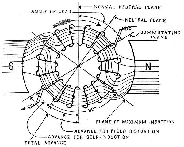
Fig. 303.—Brush adjustment for self-induction. For convenience an electric current is regarded as having weight and hence possessing the property of inertia. The current then during commutation cannot be instantly brought to rest and started in the reverse direction but these changes must be brought about gradually by an opposing force. Hence by advancing the brushes beyond the neutral plane as illustrated, commutation takes place with the short circuited coil cutting the lines of force so as to induce a current in the opposite direction; this opposes the motion of the current in the short circuited coil, brings it to rest and starts it in the opposite direction, thus preventing sparks. Figs. 301 to 303 should be carefully compared and thoroughly understood.
Ques. What should be noted with respect to the different planes?
Ans. The commutating plane should be carefully distinguished from the normal neutral plane and from the neutral plane, as shown in fig. 303.
Commutation.—In order to understand just what happens during commutation, a section of a ring armature may be used for illustration, such as shown in fig. 304. Here the coils A, B, C, D, E, are connected to commutator segments 1, 2, 3, 4, and the positive brush is shown in contact with two segments 2 and 3, the brush being in the neutral position. Currents in the coils on each side of the neutral line flow to the brush through segments 2 and 3; the brush then is positive.
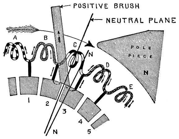
Fig. 304.—Commutation. This takes place during the brief interval in which any two segments of the commutator are bridged by the brush. The coil connecting with the two segments under the brush is thus short circuited. During commutation the current in the short circuited coil is brought to rest and started again in the reverse direction against the opposition offered by its so called inertia, or effect produced by self-induction.
Now, as the armature turns, the commutator segments come successively into contact with the brush. In the figure, segment 3 is just leaving the brush and 2 is beginning to pass under it, hence, for an instant the coil C is short circuited.
Ques. In fig. 304, what are the current conditions?
Ans. Previous to contact with segment 2, current flowed in coil C in the same direction as in coil B.
Ques. What occurs while the brush is in contact with segments 2 and 3?
Ans. During this brief interval, the current in C is stopped and started again in the opposite direction.
Similarly each coil of the armature as it passes the brush will be short circuited and have its current reversed. This is known as commutation.
Ques. What is the effect of field distortion with respect to commutation?
Ans. The neutral plane no longer coincides with the normal neutral plane but is advanced in the direction of rotation of the armature as shown in fig. 302.
The reaction of the poles N' and S' of the armature field on the poles S and N of the main magnetic field tends to crowd the lines of force into the upper pole face of the south pole of the magnet, and into the lower pole face of the north pole. This effect is due to the strong magnetic attraction between the opposite poles S and N' and N and S', and the equally strong repulsion between like poles N and N' and S and S'. Hence, the plane of maximum induction no longer coincides with the normal plane of maximum induction, but is advanced in the direction of rotation, depending upon the strength of the armature current, being shifted forward for an increase of current, and backward for a decrease of current. This distortion of the field and the consequent shifting of the plane of maximum induction naturally results in the shifting of the neutral plane from the vertical position to the inclined position as shown.
Position of the Brushes; Sparking.—In accordance with the laws of electromagnetic induction, if the bipolar ring armature shown in fig. 301 be rotated in the direction indicated by the arrow the armature current entering at the brush E will divide, one part passing through the coils on the right half of the ring, and the other part through the coils on the left half of the ring, to the brush F, from which the total current will pass out, urged by the full value of the electromotive force induced in all the coils on both halves of the ring.
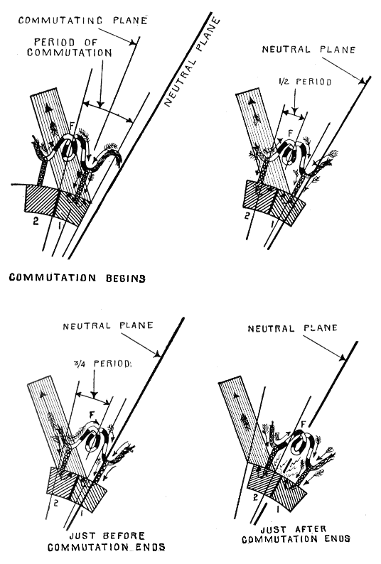
Figs. 305 to 308—Improper brush adjustment resulting in excessive sparking. When the brushes are not advanced far enough, commutation takes place before the short circuited coil reaches the neutral plane, hence, its motion is not changed with respect to the magnetic field so as to induce a reverse current till after commutation. There is then no opposing force, during commutation, to stop and reverse the current in the short circuited coil, and when the brush breaks contact with segment 1, as in fig. 308, the "momentum" of the current in coil F causes it to jump the air gap from segment 1 to segment 2 and the brush, against the enormous resistance of the air, thus producing a spark whose intensity depends on the momentum of the current in coil F. Sparking, if allowed to continue, will injure the brushes and commutator segments.
Again, if the brushes be placed at the points G and H, each half of a current entering at G, will pass through one-half of the coils on the left side and one-half of the coils on the right side of the ring, so that each half of the current will be urged forward by an electromotive force equal to the electromotive force tending to force it back, and therefore, no current will pass in or out through the brushes. From these considerations it is obvious that the proper position for the brushes would be in the normal neutral plane, were it not for the disturbing effects of armature reaction and self-induction of the current.
Ques. Should the brushes of a dynamo be placed in the neutral plane?
Ans. No.
Ques. Why not?
Ans. The brushes must be advanced beyond the neutral plane to prevent sparking.
Ques. What is the cause of sparking at the brushes?
Ans. It is due to self-induction in the coil undergoing commutation.
Ques. Explain the effect of self-induction in detail.
Ans. When commutation takes place with the brushes in the neutral plane as in fig. 304, there will be no voltage induced in the short circuited coil C. The current, therefore, which flowed in coil C before it was short circuited will cease, and as segment 3 breaks contact with the brush, it will be thrown as a perfectly idle coil upon the right hand half of the ring in which a current is flowing toward the brush. Moreover, the current which was flowing through D and 3 directly to the brush, must suddenly traverse the longer path through the idle coil C. Now, on account of self-induction, the current acts in precisely the same manner as though it had weight; that is:
It cannot be instantly stopped or started.
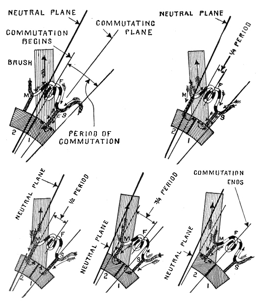
Figs. 309 to 313.—How sparkless commutation is obtained by advancing the brushes beyond the neutral plane; commutation progressively shown.
Fig. 310.—Segment 2 has come into contact with the brush and coil F, in which commutation is taking place, is now short circuited. The current now divides at M, part passing to the brush through segment 2, and part through coil F and segment 1. Although coil F is short circuited and having passed the neutral plane, is cutting the lines of force so as to induce a current in the opposite direction, it still continues to flow with unchanged direction against these opposing conditions. This is due to self-induction in the coil which resists any change just as the momentum of a heavy moving body, such as a train of cars, offers resistance to the action of the brakes in retarding and stopping its motion.
Fig. 311.—Segment 2 has moved further under the brush, and the opposition offered to the forward flow of the current in the short circuited coil F by the reverse induction in the magnetic field to the right of the neutral plane has finally brought the current in F to rest. The currents from each side of the armature now flow direct to the brush through their respective end segments 1 and 2.
Fig. 312.—Segment 1 is now almost out of contact with the brush. A current has now been started in the coil F in the reverse direction due to induction in the magnetic field to the right of the neutral plane; it flows to the brush through segment 2. The current has not yet reached its full strength in F, accordingly, part of the current coming up from the right divides at S and flows to the brush through segment 1.
Fig. 313.—Completion of commutation in segments 1 and 2; the brush is now in full contact with segment 2, the current in coil F has now reached its full value, hence the current flowing up from the right no longer divides at S but flows through F and segment 2 to the brush. If the current in F had not reached its full value, at the instant segment 1 left contact with the brush, it could not immediately be made to flow at full speed any more than could a locomotive have its speed instantly changed. This, as previously explained, is due to self-induction in the coil or the so called "inertia" of the current which opposes any sudden change in its rate of flow or direction. Accordingly that portion of the current which was flowing up from the right and passing off at S to the brush through segment 1 as in fig. 312, would, when this path is suddenly cut off as in fig. 313, encounter enormous opposition in coil F. Hence, it would momentarily continue to flow through segment 1 and jump the air gap between this segment and the brush, resulting in a more or less intense spark depending on the current conditions in coil F.
Therefore, when segment 3 leaves the brush, the current will not instantly change its path and flow through C, but will be urged by its "momentum," and jump the air gap between the brush and segment 3, thus producing a spark.
Ques. How may this sparking be prevented?
Ans. If the brushes be given additional lead, that is shifted further to the right to some position as N N, fig. 304, coil C will not remain idle during the interval it is short circuited, but will cut the magnetic lines in such a way as to induce a current in the reverse direction through it. Under these conditions, when segment 3 breaks contact with the brush, the current flowing through D does not encounter an idle coil, but one in which a current is flowing in the same direction, hence, the tendency to jump the air gap and produce a spark is reduced; with proper adjustment of the brushes, there will be no sparking.
Ques. What is the objection to very thin brushes?
Ans. Time must be allowed for reversal of the current, hence the brushes must not be so thin as merely to bridge the insulation between segments.
Ques. What is the effect of lead?
Ans. There is usually much sparking when the lead is too small; a little sparking when too great, and no sparking when just right. If the lead be excessive, there is a waste of energy due to the generation of a larger reverse current in the short circuited coil than is necessary.
Fixed Position of Brushes.—The condition for sparkless commutation is that the current in the short circuited coil be reduced to zero, and increased in the opposite direction up to the same value as that in the next coil leading. If the brushes are to remain in a fixed position, this condition will only be realized at the particular load for which the brushes are set. Thus, if the brushes be set for the average load, the reversing field will not be correct for either a weaker or stronger load. Hence, sparkless commutation with fixed brushes must be due to some other factor.
Ques. What may be said with respect to carbon brushes?
Ans. Since carbon possesses a high resistance, the drop will vary greatly with the contact area, thus affecting a difference of potential in the two segments passing under the brush and it is largely to this that sparkless commutation is due.
Ques. What is the effect of resistance on commutation?
Ans. In fig. 304 during commutation, that is, while the brush contacts with any two segments, as 2 and 3, the currents coming up through the winding on either side of the neutral plane are offered two paths to the brush: 1, direct to brush through the connecting segment, or 2, across the short circuited coil and adjacent segment. Thus, on the right side: to brush through segment 3, or across coil C and adjacent segment 2.
The current will take the path of least resistance.
At the beginning of commutation, almost the entire brush area being in contact with segment 3, the contact resistance of this segment will be much less than for segment 2; hence, not only will the current at the right flow through 3, but also the current at the left after first traversing the short circuited coil. As commutation progresses, the area of contact of 3 decreases while that of 2 increases, and the respective resistances vary in inverse proportion. Likewise the tendency of the current in the left half of the winding to take the longer path through coil C and segment 3 to the brush gradually decreases, becoming zero when the two contact areas become equal. During the second half of the period of commutation, the contact area of segment 2 becomes greater and of 3, less; thus the resistance of 2 is lowered, and that of 3 increased. Accordingly, all of the current at the left will flow through segment 2, and the current at the right will flow through C and 2 rather than through 3. In this way the current is reversed in C, and, if the brush be broad enough to allow a sufficient time interval, the current in C is built up to its full value before segment 3 leaves the brush, thus securing sparkless commutation.
This contact resistance factor in sparkless commutation is illustrated in figs. 314 to 318, it being assumed that during commutation, the brush contact resistance is inversely proportional to the area of contact, and that the winding is free of resistance and inductance. The current is taken as 40 amperes, in which case 20 amperes will flow from each side of the winding to the brush.
In fig. 314 the instant before commutation begins all the current will flow through segment A. At the end of the first quarter of the period of commutation, fig. 315, 30 amperes will flow from the right to brush through A, and from the left, 10 amperes through the short circuited coil via A and 10 amperes through B.
At the end of the second quarter or half period, fig, 316, the current through each half of the winding will flow to the brush through these respective segments.
At the end of the third quarter, fig. 317, the current from the right will divide, 10 amperes going through A, and 30 amperes traversing the short circuited coil and out through B. The entire current from the left will flow through segment B.
At the end of the fourth quarter, fig. 318, or completion of the period the current from each half of the winding will flow to the brush through B.
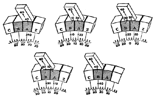
Figs. 314 to 318.—Brush contact resistance theory of commutation, neglecting self-induction and resistance in the coils. The total current is assumed to be 40 amperes made up of 20 amperes flowing toward the brush from the coils on the right and 20 amperes from the coils on the left. During commutation, that is, the interval during which the brush contacts with any two adjacent segments of the commutator, the current is assumed to vary directly as the contact area.
Fig. 314.—Beginning of commutation; segment A is entirely under the brush, and B is at the initial point of contact. For this position the currents from both sides flow to the brush through segment A.
Fig. 315.—One-quarter period of commutation. One quarter of the brush area is in contact with B and three quarters in contact with A; hence, 10 amperes will flow through B and 30 amperes through A.
Fig. 316.—Second quarter of commutation period. The brush now contacts equally with both segments, hence 20 amperes will flow through each segment.
Fig. 317.—Third quarter of commutation period. Three quarters of the brush area is in contact with segment B and one quarter with segment A; accordingly, 30 amperes will flow through B and 10 amperes through A.
Fig. 318.—Completion of commutation. The brush is in full contact with segment B and at the point of breaking contact with A, hence the entire current from both sides or 40 amperes will flow through B.
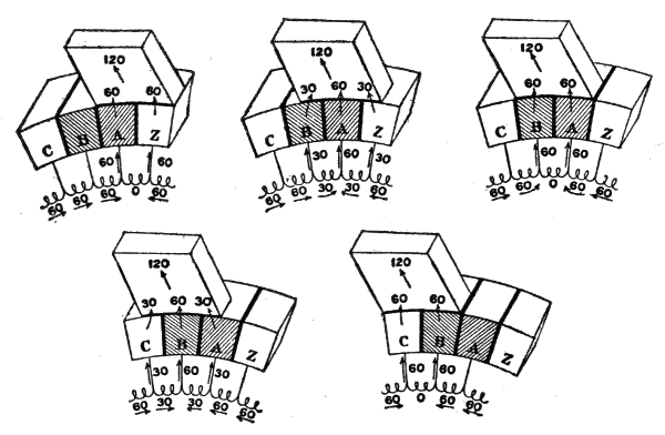
Figs. 319 to 323.--Brush contact theory of commutation for case in which the brush covers two segments of the commutator. Fig. 319 beginning of commutation; fig. 320 one-quarter period; fig. 321, one-half period; fig. 322, three-quarter period; fig. 323 completion of commutation.
Ques. What is the effect of increasing the degree of contact of the brushes?
Ans. It lengthens the period of commutation, and permits it to start in one coil before the preceding coil has entirely passed through this stage.
The effect of changing the degree of contact is shown in figs. 319 to 323, in which the width of the brush is made equal to that of two segments.
Construction of Commutators.—The commutator for a closed coil armature consists of a number of segments or L-shaped bars C of drop forged hard-drawn copper assembled around a tubular iron hub as shown in figs. 324 and 325. The bars are held in position by the nuts E, and washers F, screwed on the ends of the tube D. The bars are insulated from each other and from the washers by mica as shown by the heavy lines G, and they are also insulated from the tube either by a tube of mica H, or by a sufficient air space. The ends of the sections of winding are connected to the vertical portions of the bars K, by insertion in the slots L, where they are securely held in place by means of the binding screws, which for greater security are soldered together, and may be released from the slots, whenever necessary, by the application of a hot soldering iron.
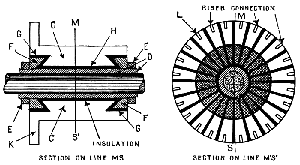
Figs. 324 and 325.—Side and end sectional views of commutator showing construction. The parts are: C, segments; D, tubular iron hub; E, end nuts; F, clamps; G, insulation; L, riser connection.
It is very important that all the parts of the commutator should be fitted together perfectly and screwed up tightly, in order to prevent looseness. Commutator segments are often made with the washers E, projecting beyond the ends, but such construction reduces the effective length of the commutator, therefore the under cut form of bar is preferable.
In the construction of commutators, the conditions of operation require that there be:
1. Adequate insulation;
It is necessary to have good insulation between each segment, and a specially good insulation between the segments and the hub or sleeve on which they are mounted; also between the segments and end clamps. The insulating material must not absorb moisture, hence asbestos, plaster, or vulcanized fibre are not used. The end insulating rings are usually built up of mica and shellac, moulded while hot under pressure to the correct shape.
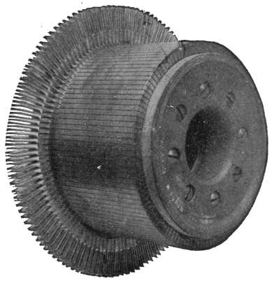
Fig. 326.—Front view of Western Electric Commutator for bar wound armature. This commutator is made of hard-drawn copper and insulated throughout, ventilating spaces being provided near the shaft.
2. Rigidity against centrifugal force;
Since the segments are subject to centrifugal force, they must be securely clamped in place. Screws cannot be used, for that would destroy the insulation. They are therefore held in place by insulated clamps as shown in fig. 324. These clamps should be strong and capable of holding the segments firmly in position, for if a segment should rise out of its place through centrifugal force, it would disturb the action of the brush and cause sparking.
3. Provision for wear.
The segments should be of considerable radial depth, so that the commutator may be turned down from time to time to preserve its circular form.
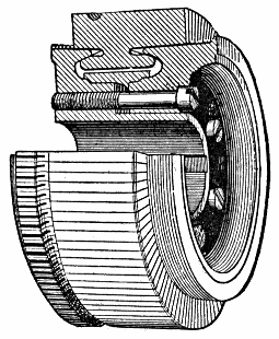
Fig. 327.—Sectional view of a General Electric commutator. The segments are of rolled or forged copper and are separated by soft mica insulating sheets. This mica must wear down evenly with the copper, hence its consistency is important. The segments are wedge shaped so that when drawn radially inward they support each other like the stones of an arch. They are drawn together by hollow cone collars which bear upon lugs projecting from the ends of the segments. These lugs are turned to form a smooth cone after the segments are assembled. The collars are insulated with mica from the segments and they are held in place by nuts upon the commutator shell or by bolts passing from end to end under the segments. The segments are also provided with lugs for connection to the windings.
Points Relating to Commutators.—1. The number of commutator segments depends on the scheme of winding and on the number of sections in the armature winding.
2. Increasing the number of bars diminishes the tendency to spark, and lessens the fluctuations of the current.
There are two practical reasons for not using a very great number of segments: it increases the cost, and in small machines the segments would be so thin that a brush of the proper thickness to collect the current would lap over, or bridge several segments.
Types of Commutator.—Commutators are made in various forms, but they may be grouped into two general types:
1. Commutators for closed coil armatures;
These consist of a large number of segments or bars, insulated from each other and varying in number according to the scheme of armature winding, and on the number of sections into which that winding is grouped.
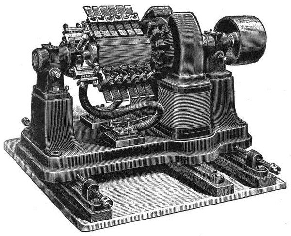
Fig. 328.—A large current low voltage bipolar dynamo built for electrolytic work and here shown to illustrate the large size commutator and brushes necessary to collect the large current. Carbon brushes would not be suitable for this class of machine because even with copper brushes, whose conductivity is much higher than carbon, the commutator must be of considerable size to give the required brush contact area. The contrast between the axial lengths of the armature and the commutator is very marked. The rocker construction is of the ordinary type, and heavy flexible cables conduct the current from the brush holders to the fixed terminals. The machine here illustrated gives 310 amperes at 7 volts when running at a speed of 1400 R. P. M., corresponding to an output of 2.17 kilowatts.
2. Commutators for open coil armatures;
This form of commutator is used on some machines designed especially for arc lighting, such as the Brush and Thomson-Houston machines. They consist of a comparatively small number of segments each of which covers a wide angle, and are separated from each other by air gaps.
3. The segments should be of considerable depth to permit returning occasionally so that their circular form may be preserved;
4. The insulating material must be such that it will not absorb oil or moisture;
Mica is best adapted for insulation, but as there are a great many varieties, differing greatly in hardness and other equalities, it is important to select the kind that wears at the same rate as the segments. If the mica be too hard, the wearing of the segments will leave it projecting and prevent proper contact with the brushes; again, if the mica be too soft, it will result in furrows or depressions between the segments into which copper dust will collect, causing short circuits.