"OWEN MERRIMAN." (continued 2)
Reading edition
Before a really efficient burner could be produced, there were, however, to be successfully encountered other problems, the precise nature of which was not so clearly apparent as that of the one above referred to; otherwise their solution would not have been so long delayed. Of these, the most important, and at the same time the most difficult, were two—namely, the right adjustment of the air supply, and the most advantageous pressure at which to consume the gas. In the earliest Argands, not the slightest provision was made for diminishing the pressure of the gas before it was consumed. It was thought that everything had been accomplished that was necessary if the holes for its emission were sufficiently minute to allow of no more than the required quantity of gas passing through them at the extreme pressure at which it was supplied to the burner. The consequence was that the gas, issuing from the burner at a very high velocity, became so intermingled with air before it was consumed, that its flame was excessively cooled; and only a small fraction of the illuminating power available was developed. Then as to the air supply. In nearly every burner produced prior to Mr. W. Sugg's invention of the "London" Argand in 1868, this was greatly in excess of the requirements; nor is it to be wondered at. Had the supply of air been delicately adjusted, while yet there was no provision for diminishing the pressure of gas at the burner, the flame would have been liable to smoke on any sudden increase in the pressure of gas in the mains; and the annoyance and inconvenience occasioned by a smoking flame were greater drawbacks than the loss of light experienced through having the air supply greatly in excess. Thus, although during this period there were many so-called "improved" burners brought into notice, in none of them were these two cardinal requirements in the production of an efficient burner clearly recognized and seriously grappled with; and, consequently, the high level of excellence to which the Argand is capable of being brought was not attained.
SUGG'S ARGANDS.
The 'London' Argand.
The invention by Mr. W. Sugg, in 1868, of the famous "London" Argand constitutes an important epoch in the history of gas lighting. Prior to that time, the construction of this class of burners had been carried out in a wholly empirical manner; and such improvements as had been effected must be looked upon as being rather the fortuitous issues of hap-hazard endeavours, than as resulting from the acquirement of clearer views as to the conditions to be complied with in order to ensure the successful operation of the burners. The invention of the "London" Argand was the first earnest attempt to abandon the former chance methods, and to proceed upon more scientific lines. Its construction shows that its inventor possessed a thorough acquaintance with the principles of combustion; while, in many particulars, it exhibits an intelligent discernment, and a successful application of the precise means required to attain a desired end. In this burner, the extreme importance of causing the gas to issue at a low pressure is for the first time clearly recognized; and the manner in which this object is so successfully attained is as simple as it is ingenious. At the entrance to the burner the gas is divided among three narrow tubes, the combined capacity of which is much smaller than that of the pipe supplying the burner. Through these tubes the gas is conducted into a concentric cylindrical chamber (forming the main body of the burner), where its rapid flow is checked; the current, or swirl, which it may have acquired, is subdued; and the gas comes to a state of comparative rest before it issues into the atmosphere and is consumed. The top rim of this concentric cylinder is pierced with 24 holes, the aggregate area of which is considerably greater than that of the three supply-tubes; thus ensuring that the gas shall be delivered at a much lower pressure than that at which it enters the burner. By dividing the gas into three streams, which enter the cylindrical chamber at equidistant points in its circumference, the supply is equally distributed throughout the entire ring of holes; and a flame of even and regular shape is the result.
The arrangement by which, in this burner, the air supply is obtained and regulated is as noteworthy as are the means adopted for controlling the pressure of the gas. The opening within the circular ring of holes is much smaller than in previous Argands; thereby proportionately reducing the quantity of air supplied to the inner surface of the flame. The space between the cylindrical body of the burner and the glass chimney is occupied by a truncated cone of thin metal, the upper edge of which is on a level with, and reaches to within a very short distance of the rim of the burner; while its base rests upon the gallery supporting the chimney. By means of this cone, all the air entering between the burner and the chimney is directed upon the immediate surface of the flame; thereby promoting intensity of combustion, and a higher illuminating power of the flame. Then the chimney itself is of such dimensions that, with the quantity of gas for which the burner has been constructed, just sufficient air is drawn upon the flame to completely consume the gas by the time the top of the chimney is reached; a flame of such length as to nearly reach to the top of the chimney, without smoking, being the most effective and economical for the quantity of gas consumed.
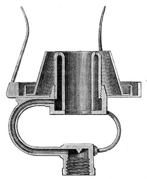
Fig. 14.—Sugg's "London" Argand. (Full Size.)
Another matter which tended not a little to enhance the results yielded by this burner was an alteration in the material of which the body of the burner was constructed. In previous Argands, this had, in almost every instance, been metal; whereas in the "London" burner steatite was employed. How the illuminating power of the flame is affected by the material of which the burner is constructed has been gone into so fully before (in relation to flat-flame burners), that it is unnecessary to dwell upon the matter here; only remarking that as in Argands the contact surface between the burner and the flame is relatively so much greater than in flat-flame burners, the cooling of the flame due to this cause is proportionately increased.
So great was the improvement effected by this burner in the illuminating power developed from the gas consumed, so obvious its superiority to every previous Argand, that it was immediately adopted by the Metropolitan Gas Referees as the standard burner for testing ordinary coal gas within the area of their jurisdiction; and from that time down to the present it has continued to be prescribed in Acts of Parliament as the burner to be employed in testing ordinary coal gas, not only in the Metropolis, but generally throughout the United The standard test burner. Kingdom. But although, as the standard test-burner, the original "London" Argand can still be obtained, it has been far surpassed, in the results yielded, by a new series of Argands, in which the same ingenious inventor has still further applied the principles first put into practice in the former burner. In this newer series of burners, the details of construction before adopted are modified in two or three particulars; but without departing from the general principles embodied in the arrangement of the earlier burner. Thus the holes in the ring are considerably larger, while the three supply-tubes remain of exactly the same capacity as before; by which means the gas is delivered at a much lower pressure. As the increased size of holes necessitates that the cylindrical body of the burner should be of enlarged diameter, the opening in the centre becomes of greater area The improved "London" Argand. than before. Were it to remain so, it would permit too large a quantity of air to be drawn upon the inner surface of the flame; to obviate which result a metal spike rises in the centre, reducing the area of the opening, and proportionately diminishing the quantity of air which would otherwise be admitted at this part of the burner. The arrangement for regulating the air supply to the outer surface of the flame is likewise modified, but in a different direction. The upper edge of the cone is brought nearer to the rim of the burner, and slightly curved, so as to direct the air more completely upon the flame; while the base of the cone, instead of extending to the glass chimney in an unbroken surface, is pierced by a number of holes, which admit air between the cone and the chimney. The action of this third current of air is to keep the chimney cool, and to steady the flame; and, in addition, it may be that it provides a supply of air to support and intensify combustion at the upper extremity of the flame. The combined effect of these alterations is to cause the burner to develop from 7 to 12 per cent. more light from the gas consumed, than is yielded by the original "London" Argand.
Silber's Argand burner. The Silber Argand, which is a remarkably efficient burner, in the main features of its construction is very closely related to Mr. Sugg's later Argands just described. The air is directed on to the outer surface of the flame, as in those burners, by a curved deflector, of which the upper edge is, however, at a higher level than in Mr. Sugg's burners. Air is also admitted between the deflector and the glass chimney. The most striking divergence in its construction from that of Mr. Sugg's burners is contained within the opening in the centre of the burner. Instead of a solid metal spike, there is a brass tube, through which, as well as between its circumference and the cylindrical body of the burner, air can enter to feed the inner surface of the flame. In addition to promoting the steadiness of the flame, it would appear that the air entering through this inner tube supports the combustion of the gas at the tail of the flame. The arrangements for diminishing the pressure of the gas within the burner, and for ensuring its equable distribution to all parts of the ring of holes, though quite different, seem to be scarcely less complete than those employed in the "London" burner. From the nipple which connects the burner to the gas supply, the gas enters (by four minute perforations) into a horizontal chamber, where its velocity is checked, and whence it is conveyed into the cylindrical chamber forming the main body of the burner. The very satisfactory performances of the burner (which are in advance of those of the standard Argand) sufficiently attest the correctness of its construction.
Multiple Argands. For consuming large quantities of gas, double or treble Argands are constructed. These consist, in effect, of two or three Argand burners placed concentrically to each other within one chimney. Mr. Sugg has produced a series of burners of this class, designed to pass quantities of gas ranging from 15 to 55 cubic feet per hour; and, in some instances, exceeding even the latter figure. These burners, with ordinary (16-candle) coal gas, give a light equal to 4 candles per cubic foot of gas consumed; which is a considerably better result than is afforded by the standard burner. The cause of their yielding results so superior to the ordinary Argand is found in the circumstance that their flames present a much smaller surface area to the cooling action of the air, in proportion to the quantity of gas consumed. The arrangement of these burners differs from that of the improved single Argands, which have been described, only in that there are two or more steatite cylinders, each fed by its own supply-tubes, and having its own distinct ring of holes; while the space between the cylinders is so proportioned as to admit no more than the quantity of air required to produce the necessary intensity of combustion.
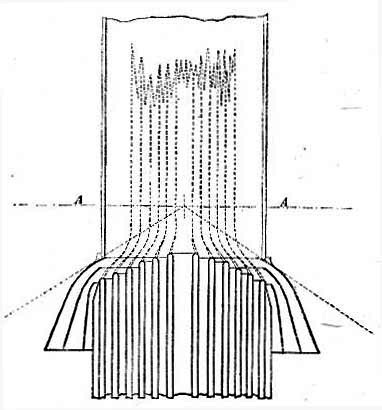
Fig. 15.—The Douglass Argand. (A A, Focal Plane, or Belt of Strongest Light.)
THE DOUGLASS BURNER.
The multiple or concentric Argand invented by Mr. (now Sir) J. N. Douglass, the Engineer to the Trinity House, may be mentioned here. This burner is of the type of those last noticed, but possesses certain peculiar features which give it a distinct claim to novelty. As will be seen by the accompanying illustration, the concentric cylinders of which the burner is composed terminate at different heights; their tops forming a regular gradation of steps, of which the innermost is the highest. These cylinders are of considerable depth, permitting the gas and air to be heated by contact with their surfaces before the point of ignition is reached. The essential feature of the invention, however, is a series of deflectors of peculiar shape, which, in addition to directing air on to the surfaces of the flames, are so formed "as to force the outer flame or flames on to the inner flame or flames in the manner illustrated." By this means the flames are concentrated and united into one, and combustion is quickened; and, a greater intensity of heat being thus attained, the illuminating power is much augmented. When this burner was first brought into notice, in 1881, high hopes were entertained as to its future. The results which it was said to afford, being far in advance of anything previously obtained from a simple Argand, seemed to promise for the burner a speedy and unequivocal success. At the North-East Coast Marine Exhibition, held in 1882, a burner with ten rings was exhibited, which was reported to develop, from 16-candle gas, 6 candles per cubic foot—a truly remarkable result to be given by so simple a burner. But, notwithstanding its apparently successful introduction, the burner has made little or no headway in the direction of its practical application. Indeed, it may almost be said to have faded altogether out of public view. This would seem to imply that there are difficulties in the way of its successful working, when brought under ordinary conditions, which were not foreseen at the time of its invention.
CHAPTER IV.

Throughout this treatise, much has been said of the relation which the pressure of gas, at the point of its delivery from the burner, bears to the illuminating power of the flame yielded—sufficient to show that the maintenance of a low and equable pressure in the gas supply is one of the conditions most imperative to be observed for the attainment of economy in combustion. Ordinarily, however, this condition does not obtain at the consumers' burners. The exigencies of distribution require that, in order to maintain a sufficient supply wherever gas is needed, a much higher pressure should be kept in the mains than is requisite for developing, at the burner, the best Effects of excessive pressure with Argand and flat-flame burners. results from the gas consumed. Moreover, the pressure at any one point is subject to continual fluctuations from the variations in the consumption of gas going on in the neighbourhood. For instance, where a number of burners are in operation in a house, consuming about the exact quantities of gas for which they have been constructed, when part of them are shut off the gas supply to the remainder is in excess of what is required; and, consequently, the burners do not develop the same proportion of light from the gas consumed as formerly. Where a large consumption of gas is suddenly discontinued (as in the business parts of a town, when the shops and warehouses are closed), the increase of pressure that is experienced at the burners which remain in operation is very manifest. The effect of this increase in the pressure of the gas supply is seen in different directions in Argand and flat-flame burners. In the former, it causes the flame to smoke, by permitting more gas to pass through the burner than can be properly consumed; in the latter, by cooling the flame below the temperature required for effective combustion, it reduces, in proportion to the extent to which it is higher than the original pressure, the illuminating power developed per cubic foot of gas consumed.
The gas regulator. Seeing that economy in combustion can only be attained under the conditions of an equable pressure, it becomes necessary to subdue the fluctuations above referred to, or at least to prevent their reaching the burner. To this end the regulator, or governor, is employed. In this instrument, a bell dipping into, and sealed in liquid—or else a flexible leather diaphragm—is actuated by the pressure of the entering gas, and so connected with a valve as to reduce the area of the opening which permits gas to enter the instrument in proportion to the pressure of gas at the inlet; by which means an equable pressure is maintained at the outlet, no matter what the quantity of gas which is being consumed, or how the pressure may vary in the inlet-pipe. By the aid of a governor, fixed on the service-pipe at the entrance to a building, the pressure of gas at the various burners is rendered fairly uniform; yet, even then, perfect equality of pressure is not obtained. The slight friction which the gas experiences in flowing through the pipes causes the burners to be supplied at somewhat lower pressures, the farther they are removed from the burner. And, again, owing to its low specific gravity, gas tends to gain in pressure with an increased elevation; each rise of 10 feet adding about 1-10th of an inch to its pressure. From this cause a higher pressure is experienced in the upper than in the lower rooms of a building. This peculiarity was observed at an early period in the history of gas lighting; as Clegg mentions that, in cotton-mills, check-taps were employed to regulate the pressure of gas at each floor. [12] In order, therefore, to obtain the desired regularity of pressure in the gas supply, governors must be employed for each storey; or, what is better still, each burner must have its own separate governor. And this brings us back to the subject with which we are more closely concerned.
The governor-burner, as its name implies, consists of a governor, as described above (but, of course, on a smaller scale) combined with a gas-burner; the governor being adjusted so as, whatever excess of pressure there may be in the gas-supply pipes, to permit only the quantity of gas to pass which the burner is intended to consume. Obviously, the principle herein contained is capable of receiving numerous applications. It can be, and is applied with equal success to Argand and flat-flame burners; while the modifications which obtain in the manner of constructing the regulating portion of the apparatus are almost as numerous and as varied as are the burners themselves. As the main features exhibited by one are common to all, it is unnecessary to go into the details of their several constructions. It will suffice to take two or three of the most successful, or the best known, as representatives of the whole.
Giroud's Rheometer. Among the first in order of time—and still retaining no unworthy position in order of merit—is the "rheometer," or "flow-measurer," of M. Giroud. In this instrument a light metal bell is sealed in glycerine contained in a cylindrical case; the bottom of this latter containing the inlet-pipe, screwed for connecting to the ordinary fittings, while from the centre of its cover rises a tube leading to the burner. The bell is pierced by a small hole for the passage of the gas, and is surmounted by a cone-shaped projection, which constitutes the valve of the instrument. As the pressure of the entering gas lifts the bell, it causes this cone-valve to enter the mouth of the tube leading to the burner; reducing the area of the opening in proportion to the pressure of gas acting upon the under side of the bell, and so permitting only the required quantity of gas to pass to the burner. It might be thought that the presence of liquid would constitute an objection to the use of the instrument; but, as glycerine does not evaporate, when once the instrument is fixed and properly adjusted, it needs no further attention. With an excessive initial pressure, there is, however, a liability of the gas to bubble through the sealing liquid, and so destroy the efficiency of the instrument; but this might be obviated by increasing the depth of the bell, and so giving it a greater seal. The instrument is very reliable for the purpose which it is intended to fulfil; delivering, through a considerable range of pressure beyond that required to raise the bell, the exact quantity of gas for which it has been adjusted. It may be added that the rheometer has an advantage over many instruments of its class, in that it presents so little obstruction to the downward rays of the flame.
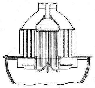
Fig. 16.—Giroud's Rheometer.
Sugg's Christiania governor-burner. Mr. William Sugg, in his regulator or governor, adopts an entirely different arrangement to the foregoing. The valve is placed at the inlet of the governor; and not at its outlet, as in the instrument just described. Instead of a metal bell, a diaphragm of thin and very flexible leather is employed, which is raised by the pressure of the entering gas, and, in turn, actuates the valve; closing the entrance to the governor in proportion to the pressure of gas acting upon it. The orifice communicating between the under and the upper side of the leather diaphragm is controlled by a screw, whereby the quantity of gas delivered to the burner can be regulated according to requirements; but when once it has been adjusted to give any desired pressure of gas at the burner, this pressure will be strictly maintained, no matter with what excess of pressure (within reasonable limits) the gas may be supplied to the instrument. The improved "London" Argands produced by Mr. Sugg (the details of the construction of which have been already described) are too delicately adjusted to be applied with advantage directly to the ordinary consumer's gas-fittings, or wherever any variation in the pressure of the gas supply is likely to be experienced. However, with the addition to them of the above governor, their use becomes as easy and simple as that of other burners; and thus the gas consumer is enabled to obtain the benefit of the most improved apparatus without being called upon to exercise the constant care and attention which, without the aid of the governor, would be necessitated. Besides being applied to Argands, this governor is successfully applied by its inventor to his flat-flame burners. In conjunction with a simple steatite burner of the latter class, it has received a very extended application, under the name of the Christiania governor-burner.
Recently, however, a new type of governor, for application to burners, has been brought out by the same manufacturer, the construction of which is very different to that of the instrument referred to above; and as it is somewhat simpler in its details, and withal appears to be cheaper in construction, it seems destined to supersede the former instrument. In this new governor, instead of a leather diaphragm, there is a bell (or float) of steatite, which is free to move, in the manner of a piston, within an inner cylindrical chamber contained within the outer case of the instrument. Attached to the centre of the Sugg's Steatite-float governor-burner. float, and on its upper surface, is a tube sliding within another tube of somewhat larger area; the latter forming a continuation of the inner cylindrical chamber. The smaller tube is open at both ends, and thus communicates from below to above the float; the outer tube is closed at the top, but has an orifice in its side. The action of the instrument is as follows:—The gas, entering below the float, passes through the inner tube to the upper part of the cylindrical chamber, and thence, through the orifice in the outer tube, to the burner. As the pressure of the entering gas exceeds that required to overcome the weight of the float, the latter is raised; the tube which is attached to it being propelled farther into the outer tube in which it slides, and, in so doing, partially closes the orifice in the side of the latter. In this way, according to the pressure of the gas acting upon the under side of the float, the area of the opening through which it must flow to get to the burner is reduced; and so the quantity of gas which issues from the burner remains the same under all pressures above that required to actuate the float. The instrument appears to be as reliable as it is simple, and to contain few parts calculated to get out of order; but, of course, whether or not it will retain its good qualities after long-continued use can only be proved by experience.
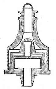
Fig. 17.—Sugg's Steatite-Float Governor.
Peebles's needle governor-burner. Another instrument of this class—the last which I shall notice—is Peebles's needle governor-burner. For simplicity combined with remarkable efficiency, it is undoubtedly ahead of all its compeers. Somewhat similar in principle to Giroud's rheometer, it differs from that instrument in many of the details of its construction; and while dispensing with the use of liquid, maintains equal efficiency in operation. It was described as follows by Dr. W. Wallace, in a lecture on "Gas Illumination," delivered before the Society of Arts in January, 1879: [13]—"In a little cylinder stands a so-called needle, on the point of which rests a flanged cone of exceedingly thin metal. At one side of the cylinder there is a small tube leading away the gas, and the orifice of which is influenced in area by the action of the cone. The instrument, by means of a screw leading into the side tube, can be made to deliver any desired number of cubic feet, which it does with surprising accuracy, provided that the pressure of the gas is not Efficiency of the needle governor-burner. less than 6-10ths of an inch." As to the efficiency of the instrument, Dr. Wallace proceeded to state:—"In trials that I have made, I have not found the variations of volume at different pressures to exceed 1 per cent." For situations where this extreme nicety of operation is not absolutely essential, or where the rate of consumption is to be invariable, the instrument is constructed in a somewhat modified and simpler form. The small tube on the side of the instrument is dispensed with, and the gas permitted to pass through perforations in the lower part of the cone. With this alteration there is a nearer approach to the construction of the rheometer; but, as in that instrument, there is no provision for altering the rate of consumption to suit different circumstances.
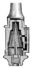
Fig. 18.—Peebles's Needle Governor.
CHAPTER V.

As was remarked in the introduction to this treatise, recent years have witnessed a very considerable advance in the construction of gas-burners, and in the amount of light capable of being developed from each cubic foot of gas consumed. Undoubtedly the most noticeable feature of this advance is the successful application of the regenerative, or, as it would be more appropriately designated, recuperative system. Briefly stated, this consists in utilizing the heat of the products of combustion from the gas flame (which otherwise would be dissipated into the atmosphere) to raise the temperature of the gas before it is ignited; and, likewise, of the air necessary for combustion. The temperature of an illuminating gas flame is usually Temperature of a gas flame. estimated to be between 2000° and 2400° Fahr.; and as the products of combustion must leave the flame at a temperature little, if at all, inferior to the former figure, it must be evident that there is an ample margin of heat for employment in this direction. A considerable proportion of the large amount of heat conveyed by those products of combustion which, under ordinary circumstances, is imparted to the surrounding atmosphere—often elevating its temperature to an unnecessary and prejudicial extent—is, by this method, returned to the flame; intensifying the process of combustion, and augmenting, in a remarkable degree, the illuminating power developed from the gas consumed. Thus the ultimate effect of the operation is to produce a concentration of heat in the flame, and the conversion of superfluous heat into beneficial light. Within a comparatively recent period, the utility of this process was strongly disputed; and it was stoutly maintained, by many persons, that as the immediate effect of ignition was to cause a temperature of more than 2000° Fahr. to be attained, the heating of the gas and air prior to their combustion could produce little or no beneficial effect upon the illuminating power of the flame. However, the falsity of this view of the case is conclusively demonstrated by practical experiment; the remarkably high results yielded by burners that have been constructed upon the regenerative system sufficiently attesting the correctness of the principles upon which they are founded.
Although, in general, both the gas and air supplies are heated, it is chiefly due to the latter that the beneficial effect noticed is produced; and this for two reasons. First, because the quantity of air is so much greater than the gas it is required to consume; being, at the nearest approach to theoretical perfection, fully six times its volume. Second, because four-fifths in volume of the air consists of inert nitrogen, which does not contribute anything to the heat of the flame, but, when applied in its normal, cold condition, abstracts no inconsiderable proportion of heat from it. Yet the heating of the gas itself is not without very appreciable influence. In an ordinary gas flame there is always an area of non-illumination around, and extending to a variable distance from the burner head. This is caused partly by the conduction of heat from the flame by the burner; but, in a greater degree, by the cooling action of the issuing stream of cold gas, as is shown by its extending farther from the burner in proportion to the pressure or velocity with which the gas issues. The prejudicial effect due to the former is obviated to a great extent by constructing the burner of steatite, or other non-conducting material. To remedy the latter, nothing will avail but the heating of the gas supply.
Effects of heating the gas and air. The effect of heating the gas is to enlarge the area of the illuminating portion of the flame, and, in a minor degree, to enhance the intensity of incandescence to which the carbonaceous particles are raised. When the gas issues from the burner at a temperature little inferior to the temperature of ignition, the hydrocarbons it contains are immediately decomposed; the liberated particles of carbon are raised to the temperature of incandescence; and the illuminating area of the flame is extended downwards, even to the surface of the burner. The heating of the air operates chiefly to produce and maintain a more elevated temperature of the flame; and, in this manner, contributes to the development of a higher illuminating power from the same area of flame. In the case of ordinary gas flames, the cold atmosphere by which they are surrounded, by abstracting heat from the flame, prevents the most favourable conditions for the development of light from being attained. When, however, the air immediately surrounding the flame has been previously heated, the particles of carbon (the incandescence of which furnishes the desired illuminating power) attain to a much more exalted temperature; and, consequently, give out a greater degree of light.
But there is yet another direction in which the prior heating of the air supply contributes to the development of improved illuminating power. Being heated, its density is lowered; so that in any given volume of air there is less weight of oxygen than when cold. The consequence is that as less oxygen is presented to a given surface area of flame, the separated particles of carbon remain for a longer period of time in the incandescent condition before being entirely consumed. Thus there are three distinct results produced by heating the gas and air before combustion—namely, first, the particles of carbon are liberated earlier in the flame; second, they are raised to a more exalted temperature; and, third, they remain for a longer time in the incandescent condition. The combined effect of all three is the improved illuminating power developed from the gas consumed.
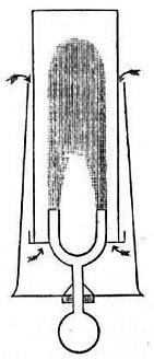
Fig. 19.—Bowditch's Regenerative Gas-Burner.
So far back as the year 1854, the principle of heating the air supply to an Argand burner, by means of waste heat from the flame, was partially applied, with some success, by the Rev. W. R. Bowditch, Bowditch's regenerative burner. M.A., of Wakefield. Mr. Bowditch's burner, which is shown in the accompanying diagram, contained, in addition to the ordinary chimney, an outer glass chimney, which extended for some distance below the inner one, and was closed at the bottom; so that all the air needed to support the combustion of the gas was required to pass down the annular space between the chimneys, and in its passage became intensely heated by contact with the hot surface of the inner chimney, as well as by radiation from the flame itself. This burner contained many defects. Amongst others, the inner chimney could not long withstand the intense heat to which it was subjected, and, in consequence, had to be frequently renewed; the heating of the air was not effected solely by the products of combustion, but, perhaps in a greater degree, by the abstraction of heat from the flame itself; while, at best, this heating was but partial. Yet, these defects notwithstanding, the burner showed very clearly the beneficial results attending even a partial application of the principle; as, in the illuminating power it developed from the gas consumed, a clear gain of 67 per cent. over the ordinary Argand burner was obtained. Although the drawbacks connected with the construction of Mr. Bowditch's burner prevented its ever receiving general, or even extensive adoption, its simplicity has gained for it the distinction of being freely copied by so-called inventors of a later day.
It was left to Herr Friedrich Siemens, of Dresden, to produce a burner which, while applying the principle of regenerative heating in the most scientific and complete manner, should also be adapted to the ordinary conditions of gas lighting. After much experimenting on the Invention of the Siemens regenerative burner. subject, a burner embodying the essential features of the regenerative system was invented by this gentleman in 1879; and so great was the advance which its performances manifested over anything previously attained, so wide the prospect of further achievements which was opened out, that it may fairly be said to have inaugurated a new era in gas illumination. In this burner the products of combustion were made to give up a considerable portion of their heat to the gas and air, as the latter passed to the point of ignition; the flame itself not being called upon to contribute in any degree to this result. Although, as was but natural, the first attempts towards the construction of such a burner were very crude, and but partially successful in their results, the inventor persevered in his endeavours to work out his ideas into practical and thoroughly satisfactory shape. It was not until after it had gone through many modifications that the burner acquired the peculiar form which now distinguishes it, and attained to its present stage of perfection. Before proceeding to describe an example of the burner as now constructed, it is necessary to state that the principles embodied in Herr Siemens's invention are equally well adapted—and, indeed, are applied with equal success—to the construction of flat-flame and Argand burners; but as the distinctive features of the invention are common to both classes of burners, it will be quite sufficient to describe in detail one of the latter type.
A prominent feature in the appearance of the Siemens burner, as will be seen from the annexed illustration, is a large metal chimney, for creating a draught to carry away the products of combustion. The entrance to this chimney is situated a little above the apex of the flame; but there is a branch flue connecting the main chimney with the interior of the burner. The body of the burner is of metal, and its interior is divided into three concentric chambers. Of these, the innermost is open at the top, and is surmounted by a porcelain cylinder, which, when the gas is lighted, is surrounded by the flame. This chamber is closed at the bottom, but communicates at the side with the before-mentioned branch tube, or flue, leading to the main chimney. The intermediate chamber communicates, at its lower extremity, with the gas supply; and terminates, a short distance from the top of the burner, in a number of small metal tubes, which convey the gas to the point of ignition. The outer chamber is open both at top and bottom, and is for conveying air to support the combustion of the gas. In order to promote greater intensity of combustion, there is a notched deflector at the summit of the latter chamber, and another on the lower part of the porcelain cylinder, which cause the air to impinge more directly upon both sides of the flame. There is also an arrangement for introducing air between the outer casing of the air chamber and the glass chimney which encloses the flame; its object being to keep the chimney cool.
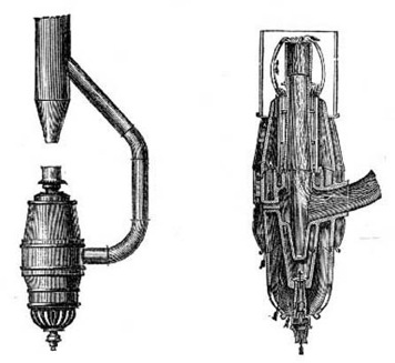
Elevation. —Enlarged Section of Combustion Chambers. Fig. 20.—Siemens's Regenerative Gas-Burner.
Action of the Siemens burner. The action of the burner is as follows:—When the gas is ignited at the ring of tubes, the heated air and products of combustion, which rise from the flame, create a draught in the main chimney. Through the communication established by means of the lateral flue, a partial vacuum, or area of low pressure, is induced in the innermost chamber of the burner, and within the porcelain cylinder which surmounts it. As the flame terminates close to the mouth of the latter, the greater portion of the products of combustion, instead of going into the main chimney, are sucked into the porcelain cylinder; and thus a current is set up through the interior of the burner, and by the lateral flue, to the main chimney. The heat carried away by the products of combustion is communicated, through the walls of the chambers, to the entering gas and air; and by this means the latter are heated to a very high temperature before they issue from the burner and are consumed. The consequence is that a much greater intensity of combustion is maintained; the carbon particles are separated earlier in the flame, and are raised to a more exalted temperature; and the ultimate effect is a higher yield in illuminating power per cubic foot of gas consumed. Independent tests by various experienced photometrists have conclusively shown that a light equivalent to that from 5 to 6 candles is obtained per cubic foot, from gas which, in the standard "London" Argand, yields a light of only from 3 to 3½ candles.
While the advantages of the Siemens burner are many and obvious, it is not without its disadvantages. These partly arise from causes connected with the very observance of the conditions necessary to Defects of the Siemens burner. secure the efficiency of the burner. With every advance in the more efficient operation of gas-burners, increased care and attention are demanded in their employment, in order to obtain the benefits they are calculated to yield. Indeed, it would almost appear that the nearer the approach to perfection which is made in the construction of a burner, the greater must be the drawbacks to its general adoption. Thus, in the burner under notice, if the gas supply is allowed to become in excess, the tail of the flame enters the porcelain cylinder, and soot is deposited in the interior of the burner; obstructing the passages, and impairing the burner's action. Then, to cause the burner to yield its highest results, it is necessary that the air supply be accurately adjusted to the quantity of gas being consumed. To this end the entrance to the air chamber, at the bottom of the burner, is covered by a perforated semi-circular cup, by turning which the quantity of air entering the burner can be increased or diminished as required. Moreover, the bulky construction of the burner, with its accompaniment of chimney and flue, and its complicated arrangement of tubes and chambers, imparts to it a somewhat clumsy and inelegant appearance, which is calculated to impair the favour with which its remarkable performances cause it to be regarded. But these drawbacks are far outweighed by the undoubted advantages conferred by the burner—in improved illumination combined with economy of combustion, and the facilities it affords for securing perfect ventilation.
Encouraged by the success of Herr Siemens, other inventors have followed in his footsteps; with the result that there are now a variety of burners before the public, embodying the same principles, but differing in the details of their construction and in the measure of their efficiency. Of these may be mentioned Grimston's, Thorp's, and Clark's; and without describing in detail the construction of the several burners (of which further particulars will be found in the "Register of Patents" in the Journal of Gas Lighting [14]), it must suffice to refer to the salient points and distinctive features of each.
Grimston's regenerative burner. Grimston's burner (shown on the next page) consists, in effect, of an Argand burner turned upside down; the gas issuing from the bottom ends of a number of small tubes placed in a circle. The jets of flame—first directed downwards from the mouths of these tubes—by a conoidal deflector in the centre of the ring, are caused to spread outwards, and assume a horizontal direction; and by their amalgamation with each other a continuous sheet or ring of flame is produced. The horizontal direction of the flame is maintained by its passing underneath a metal flange, faced with white porcelain, or other refractory material; the supply of gas being adjusted so that the flame just terminates at the outer edge of this flange. Before entering the chimney, the products of combustion are caused to flow through a number of vertical tubes contained in a cylinder, which is concentric to an inner cylinder containing the gas-supply tubes. The outer cylinder is traversed by the air needed for the support of combustion, which is to become heated before reaching the point of ignition; and in order the more completely to enable the products of combustion to impart their heat to the entering air, the cylinder is further intersected by strips of wire gauze, which pass around and between the tubes (see fig. 22, on next page). By these means the air is intensely heated; and, passing among the narrow burner tubes through which the gas is conveyed, gives up a portion of its heat to the latter before the point of ignition is reached. Thus, in a very simple manner, both air and gas are raised to a considerable temperature before combustion takes place.
With regard to the efficiency of the burner, at the exhibition of gas appliances held at Stockport in 1882 (where a gold medal was awarded to it, as well as to Thorp's burner, to be referred to hereafter), with a consumption per hour of 9·84 cubic feet of 17·5 candle gas, an illuminating power of 60·67 candles was obtained (equal to 6·16 candles per cubic foot); while, on another occasion, when the burner was consuming 8·94 cubic feet per hour, an illuminating power of 51·5 candles (equal to 5·76 candles per cubic foot) was obtained from gas of the same quality. It is claimed for this burner that equally good results are obtained with small sizes as with large; and this, if borne out in actual practice, should go far towards ensuring the success and extensive adoption of the burner.
Fig. 21.—Grimston's Regenerative Gas-Burner.
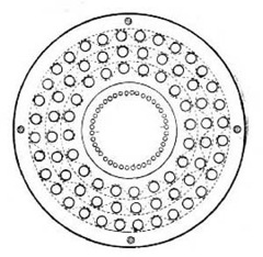
Fig. 22.—Grimston's Burner. Plan, showing Regenerating Arrangement.
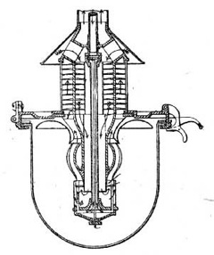
Fig. 23.—Thorp's Regenerative Gas-Burner.
Thorp's regenerative burner. Thorp's burner produces a cylindrical flame, like that of the Argand, but without the aid of a glass chimney which is a necessary adjunct to the latter burner. By means of a deflector on the inner side of the flame, the latter is made to curve outwards and assume a somewhat convex form, so as to obviate the shadow which otherwise would be cast by the gas chamber at the bottom of the burner. Above the flame is a cylindrical chimney, divided by a vertical partition into two concentric chambers, which are intersected by a series of metal gills, or projections, continued through both chambers. The outer chamber is for conveying away the products of combustion; the inner one for the passage of air to feed the flame; while down the centre of the inner chamber there passes a tube conveying the gas to the point of ignition. The hot products of combustion pass up from the flame through the outer chamber, and give up the greater portion of their heat to the projections; by which it is conducted into the inner chamber, and transferred to the incoming air. A common imperfection of regenerative burners is that, in consequence of the diminished rate at which the gas flows through the burner when expanded by heat, when starting the burner the gas must be only partially turned on, and the quantity gradually increased as the burner becomes heated; thus necessitating considerable attention. To prevent the need for this attention, there is in Thorp's burner an ingenious contrivance for automatically regulating the quantity of gas admitted to the flame. The central gas-tube, which is referred to above, contains a brass rod, fixed at one end, and at the other connected to a valve controlling the quantity of gas that enters the tube. At first, when the gas is lighted, this valve is almost closed; but as the rod becomes heated it elongates, gradually opening the valve until the full quantity of gas is admitted which the burner is intended to consume. At the Stockport exhibition, Thorp's burner was tested with the following results, as recorded in the Judges' report. After it had burned about two hours, "it gave an illuminating power of 183 standard candles, while burning 27 cubic feet of gas per hour (equal to 6·77 standard candles per cubic foot), with gas of 3·5 candles per cubic foot.... In another experiment with the same quality of gas, after burning half an hour it yielded, under similar conditions, 154 candles with a consumption of 25·29 cubic feet per hour, which gave an illuminating power of 6·02 candles per cubic foot."
Clark's regenerative burner. There is nothing in Clark's burner that calls for special notice. In its main features it appears to be constructed upon similar lines to Grimston's burner, although the coincidence is doubtless only accidental. [15] It must, however, be added that in the details of its construction it is much simpler than the latter burner; and certainly it appears to lose very little in efficiency from its greater simplicity, as the following extract from a report by Mr. F. W. Hartley, the well-known photometrist, will show:—"With a consumption rate of 5·3 cubic feet of gas per hour, the amount of light yielded horizontally was equal to 29·79 times that of a standard candle. The light yielded per cubic foot of gas burned per hour was therefore equal to 5·62 times that of a standard candle." And the amount of light delivered immediately downwards is said to be "very sensibly greater than the amount of light delivered horizontally." Like the Grimston burner, it is of the inverted Argand form; the gas issuing from a chamber at the bottom of a tube which descends through the centre of the burner. The products of combustion escape through a chimney; and in so doing give up a portion of their heat to the entering air, which is conveyed to the point of ignition through horizontal tubes that intersect the chimney. The burner is enclosed in a suitable lantern, the lower half of which consists of a semi-globular glass; a similar arrangement being adopted in connection with the Grimston and Thorp burners.
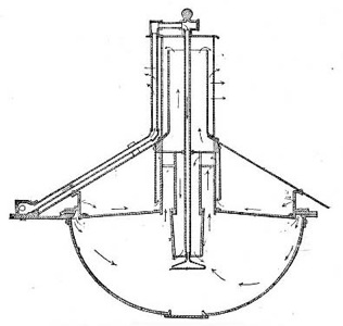
Fig. 24.—Clark's Regenerative Gas-Burner.
The three burners last mentioned have not been before the public sufficiently long to enable a reliable opinion to be formed as to their value in actual and prolonged use. Although there is no reason for supposing that such will occur in the present instance, it so often happens that the results indicated by apparatus in the experimental stage, or while still under the control of the inventor, are not borne out in practice, that it would be unwise to express any decided opinion as to their ultimate worth from existing information. It is, however, to be earnestly hoped that the marked favour with which they have been received will not be impaired on improved acquaintance; but that further experience will justify the anticipations that have been excited by the excellent performances of the burners hitherto, and demonstrate at once their durability and real usefulness.
Since writing the above, considerable activity has been shown by inventors in producing new burners upon the regenerative principle, or in improving upon existing models. Of course, as yet it is too early to arrive at a satisfactory estimate of their actual value or relative worth; but it may be hoped that, from the increased attention being devoted to the subject, some real and practical results will flow, by which the gas-consuming public will be the gainers. So far, the most promising of this class of burners that has been brought into actual use, since the introduction of the Siemens burner, is the one represented below.
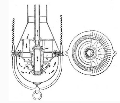
Fig. 25.—Bower and Thorp's Regenerative Gas-Burner.
It is a modification, in the direction of greater simplicity, of Thorp's former burner, illustrated and described on p. 69 of this treatise; and as its construction is based upon the same lines as that burner, further description is not required.
CHAPTER VI.

A review of gas-burners would scarcely be complete without some reference to the incandescent burners of M. Clamond and Mr. Lewis. Although their dependence upon an artificially produced blast or current of air removes them from the list of appliances applicable to ordinary conditions, the remarkable results which they afford, not less than their originality, demand for them at least a passing notice. The production of light by the agency of these burners is brought about in a manner altogether different, and is due to quite other causes than those which are concerned in the production of an ordinary illuminating gas flame. In the latter case, the illuminating power developed is solely due to the hydrocarbons contained in the gas, which are decomposed by the heat of the flame, the separated carbon being raised to a white heat. In the former, the illuminating power is not obtained directly from the gas; but advantage is taken of the heat of the flame, enhanced by the application of a blast of air, to raise to incandescence some refractory foreign material, which latter is thus made to give out light. In the Clamond burner this refractory substance is a basket composed of magnesia, spun into threads; in the Lewis burner it is a cage of platinum wire.
To the unthinking reader it may perhaps appear somewhat surprising that results so remarkable as are yielded by these burners should be obtained, while disregarding, as a source of light, the hydrocarbons contained in gas, and employing them, in common with the other constituents, solely as a source of heat. An explanation, however, is readily forthcoming. As was shown in a former part of this treatise, [16] the great bulk of ordinary coal gas consists of constituents which, in the act of combustion, produce considerable heat, but scarcely any light; the illuminating power developed in an ordinary gas flame being almost wholly dependent upon the very small proportion of heavy hydrocarbons which the gas contains. Thus, the quantity of heat-producing elements contained in the gas being quite disproportionate to the light-yielding hydrocarbons, there is always produced, in an ordinary gas flame, more heat than is necessary for effectively consuming the free carbon, which is liberated in the flame by the decomposition of the heavy hydrocarbons. This is shown by the fact that coal gas can usually be naphthalized—that is, impregnated with the vapour of naphtha—to a considerable extent before the limit of effective combustion is reached. The object aimed at in the incandescent burners about to be described is to utilize, in the development of illuminating power, the combined heat produced by the combustion of all the constituents of the gas. To this end the heat of combustion is brought to bear upon, and caused to raise to incandescence, some refractory material, extraneous to, but brought within the operation of the flame.
Effect of injecting a blast of air into a gas flame. A further explanation of the superior results yielded by these burners may be found in the employment of an artificial blast or current of air. Indeed, without some such arrangement the desired end could not be attained. The heat developed by the unaided flame is diffused over too wide an area to raise the temperature of the heated substance to the necessary degree of incandescence to enable it to give out sufficient light. By injecting a current of air into its midst, the flame is condensed into a smaller compass; and is brought to bear more directly upon the precise locality where its heat may be most effectively employed. Thus, although the total quantity of heat developed remains exactly the same as before, it is concentrated upon a smaller surface of the refractory substance; and the latter is consequently more intensely heated, or, in other words, raised to a more exalted temperature. The very superior illuminating power which is thereby obtained is due to the circumstance that the quantity of light yielded by an incandescent body increases in a higher ratio than the temperature to which it is raised.
Lewis's incandescent gas-burner. Proceeding now to describe the burners. The one invented by Mr. Lewis (various forms of which are illustrated on the next page) consists of an upright tube, connected at its base to the gas supply, and surmounted by a cap or cage of platinum wire gauze; which latter constitutes a combustion chamber, as it is there that the mixture of gas and air is consumed. Into the lower part of the upright tube the nozzle of an air-pipe is inserted, through which a supply of air can be injected, under pressure, into the burner, after the manner of a blowpipe. There are also small branch tubes leading into the upright gas-tube, and open to the atmosphere. Through these an additional quantity of air enters the burner; being drawn or sucked in by the agency of the main current, which flows through the upright tube. The resemblance to an ordinary Bunsen burner is, therefore, very close. The mixture of gas and air thus produced, when ignited, burns at the platinum cap; the heat which is developed causing the latter to become highly incandescent, and so to give out a brilliant light. To prevent the conduction of heat from the incandescent platinum, through the upright tube, a non-conducting material—such, for instance, as steatite or porcelain—is interposed between the gauze cap and the metal tube.
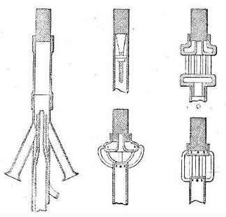
Fig. 26.—Lewis's Incandescent Gas-Burner.
The light produced by this burner is said to approximate more closely to daylight than that yielded by an ordinary gas flame (the colours of textile fabrics, for instance, being shown as well by its aid as by daylight); while, on account of its resulting from the incandescence of a fixed body, instead of being emitted from a flame, it is unaffected by a gust of wind, and maintains perfect steadiness under every condition of weather. The illuminating power developed is stated to be equal to 5 standard candles per cubic foot of gas consumed.
Clamond's incandescent gas-burner. M. Clamond's burner, which is shown in fig. 27, is a much more complicated apparatus than the preceding one, and not so easily described; but its main features may be briefly enumerated as follows:—The air (which, as in Mr. Lewis's burner, is supplied under pressure) is divided, as it enters the apparatus, into two portions. One portion is at once mixed with the gas; the remainder being conveyed, through a peculiarly constructed tube composed of small pieces of refractory material, to the combustion chamber, or "wick," as it is termed, of the burner. This "wick" is a small conical basket, made of a kind of lacework of spun magnesia, which, when raised to incandescence by the heat produced by the combustion of the gas, furnishes the desired illumination. The mixture of gas and air is subdivided, by a "distributor," into two portions, one of which goes direct to the magnesia "wick," there to be burnt, while the other is distributed among a number of tubes, forming so-called "auxiliary burners," the flames of which are utilized to heat the chief air supply; being directed upon the sides of the before-mentioned tube of refractory material, through which it is conveyed. By this means the air is raised to a very high temperature (1000° C., or 1800° Fahr., it is said) before it impinges upon the flame. The result is the production of a most intense heat within the magnesia basket; the latter being raised to brilliant incandescence, and so developing a high illuminating power.
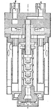
Fig. 27.—Clamond's Incandescent Gas-Burner.
The magnesia basket must be renewed after being in use a period of from 40 to 60 hours, as it gradually deteriorates by the action of the intense heat to which it is subjected; but as the cost is said to be insignificant, this should not be a great drawback. The basket is placed at the base of the burner, in order to obviate the shadow which would otherwise be cast by the apparatus; and it is attached to the main body of the apparatus by platinum wires. As to illuminating power, the only particulars which have been made public refer to the first two models constructed; one of which was said to develop a light equal to that from 6·208 candles, and the other to 9·72 candles per cubic foot of gas consumed.
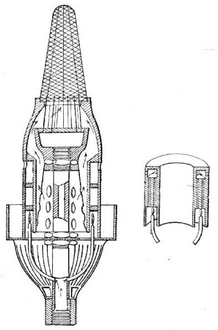
Fig. 28.—Clamond's Improved Incandescent Burner.
Clamond's new burner. In a recently designed modification of the burner (which is shown in the accompanying illustration) M. Clamond dispenses with an artificial supply of air under pressure, and endeavours to obtain similar results by other and simpler means. To this end the position of the magnesia "wick" is reversed (it being placed at the top of the apparatus); the current of gas is allowed to draw in upon itself a quantity of air by a precisely similar arrangement to that adopted in the Bunsen burner; while an additional supply of air is drawn upon the flame by the accelerated draught produced by the aid of a glass chimney. As in the more complicated and complete burner, the air supply is heated by means of auxiliary burners in the interior of the apparatus. It has been stated, on the authority of M. Clamond, that this modified burner develops, from the gas consumed, a duty of about 6 candles per cubic foot; being equal to the results yielded by the more complicated apparatus. Should this be borne out in practice, M. Clamond will have achieved a noteworthy success. It is, however, advisable to reserve expressing any definite opinion of its merits until further information is received, or until the burner has been tried in this country.
CHAPTER VII.
The burners last mentioned may be said to mark the extent of the progress that has been made, down to the present time, in the construction of apparatus for developing light from coal gas; and they remind me that I have arrived at the conclusion of my subject. From the unpretending gas-jet described by Accum—burning, with wonder-provoking steadiness and constancy, "so long as the supply of gas continued"—to the complicated apparatus of M. Clamond, is a long stretch of invention; embracing the labours of many distinct and original workers in the same field, and including numerous variations in the details of burners that have not been touched upon in the foregoing remarks. As was announced in the introduction, I have dealt in this treatise only with the more important or the more successful of the modifications that have been made from time to time in the construction of the gas-burner. In addition to the burners that have been referred to, there have been invented many others, which could not be adequately noticed without prolonging the treatise to an undue length. Some of these (the fruit of much thought and careful experiment) have obtained, in the commercial success that has attended them, no more than their merited reward; others (devoid of any real merit, and in their construction disregarding the most elementary principles of economic combustion) have been brought into somewhat extensive use by the misleading statements and false representations of their inventors, and are only tolerated through the ignorance of the public; while not a few of the latter class of burners have speedily found the oblivion which they richly deserved. Sufficient, however, has been said to show that many real improvements have been effected in the construction of gas-burners, and to prove that, with the apparatus now available, a far higher duty may be obtained from the gas consumed than was possible only a few years ago.
But although the great advance that has been made in the construction of gas-burners is undoubted, the benefits which ought to result therefrom have not been realized by the gas-consuming public; nor are they likely to be to their full extent. While the ingenious and effective inventions for utilizing the waste heat of combustion, and for lighting by incandescence, may, and doubtless will, in the course of a few years, be far more extensively adopted than at present, it is hardly to be expected that they will be generally employed. Two causes operate to preclude the latter result—namely, their first cost, and the care and attention demanded in their employment. It seems tolerably certain that for a long time yet the great bulk of coal gas, used for lighting purposes, will be consumed through the simple flat-flame burners that have done so much hitherto for the furtherance of gas lighting. Fortunately so much has been done towards the perfection of this class of burners, that, for a very slight expenditure, results may now be obtained far in advance of what could formerly be produced only by the most costly and delicate apparatus. For ordinary situations and requirements, the improved flat-flame burners produced by Bray, Brönner, and Sugg, when intelligently employed, leave scarcely anything to be desired. When intelligently employed, I repeat, and with cautious emphasis; for the best of burners will be extravagant and ineffective if employed without due regard to the conditions for which it was made. That which is most needed at the present day, and which will best ensure the continued use of coal gas for the purposes of illumination, is the more general diffusion amongst gas consumers of a knowledge of the principles of combustion, and of the simple precautions to be taken and conditions to be fulfilled in the employment of gas-burners. The apparatus that is available is both varied and effective; what is wanted is the knowledge to use it aright. By contributing to the freer dissemination of that knowledge, purveyors of gas will confer no inconsiderable benefits upon their customers, and, at the same time, will assuredly promote their own interests.
Transcriber's Note: Figure 11 and Figure 12 are identical.
Footnotes
[6] Do.