Chapter V · BARB-WIRE FENCE.
Reading edition
The invention of barb wire was the most important event in the solution of the fence problem. The question of providing fencing material had become serious, even in the timbered portions of the country, while the great prairie region was almost wholly without resource, save the slow and expensive process of hedging. At this juncture came barb wire, which was at once seen to make a cheap, effective, and durable fence, rapidly built and easily moved. The original patent for barb wire was taken out in 1868, but it was not until six years later that an attempt was made to introduce it into general use, and more than ten years elapsed before the industry attained any considerable magnitude. The rapidity and extent of its subsequent growth will be seen by the following table, showing the estimated amount of barb wire manufactured and in use during the years named, the estimated length being in miles of single strand:
Year.Tons.Miles.
1874510
1875300600
18761,5003,000
18777,00014,000
187813,00026,000
187925,00050,000
188040,00080,000
188160,000120,000
188280,000160,000
1883100,000200,000
1884125,000250,000
1885130,000260,000
1886135,000270,000
Totals716,8051,433,610
There are now fifty establishments engaged in the manufacture, and the output for 1887 is estimated at 140,000 tons.
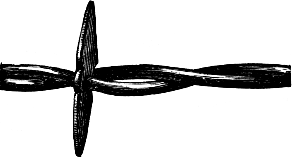
Fig. 58.—The Kelly Barb Wire.
Barb wire is not without its drawbacks as a fencing material, the most common one being the liability of serious injury to valuable domestic animals coming in contact with the sharp barbs. Many means have been devised for overcoming this evil. Some of them are illustrated in the next chapter. The direct advantages of barb wire are: First—economy, not only in the comparative cheapness of its first cost, but also in the small amount of land covered by it. Second—effectiveness as a barrier against all kinds of stock, and a protection against dogs and wild beasts. Third—rapidity of construction and ease of moving. Fourth—freedom from harboring weeds, and creating snow drifts. Fifth—durability.
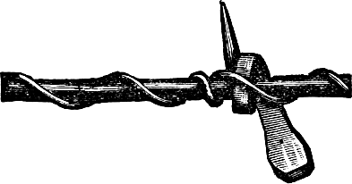
Fig. 59.—Horse-nail Barb.
Barb wire, like the harvester, the sowing machine, and most other valuable inventions, has attained its present form from very crude beginnings. The original barb wire consisted of double-pointed metallic discs, strung loosely upon plain wire. The next step was to twist this with another wire, as shown in figure 58.
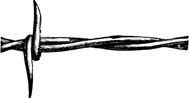
Fig. 60.—Crandall Barb Wire.
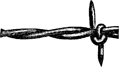
Fig. 61.—Sterling Barb Wire.
Another crude beginning was the “horse-nail barb,” which consisted of a common horseshoe nail bent around a plain wire, and the whole wrapped spirally with a smaller wire, as shown in figure 59. Various forms of two-pointed and four-pointed barb wire are manufactured, the principal difference being the shape of the barbs and the manner of coiling them around one or both of the strands. A few of the leading styles are illustrated herewith. Figures 60 and 61 show two varieties of two-pointed barb wire.
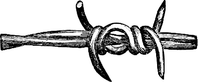
Fig. 62.—Quadrated Barb Wire.
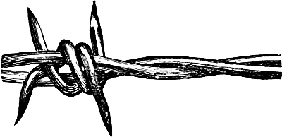
Fig. 63.—Iowa Four-pointed Barb Wire.
Of the numerous styles of four-pointed wire, three typical forms are illustrated in figures 62, 63, and 64.
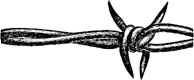
Fig. 64.—Lyman Barb Wire.
The Glidden patent steel barb wire is made in three styles, as shown in figures 65, 66, and 67. Figure 65 shows the two-point wire, in which, like the others, the barb is twisted around only one of the wires. Figure 66 shows the “thick-set” which has barbs like the other, but set closer together for such purposes as sheep folds, gardens, or other places, which require extra protection. The four-point barb wire, figure 67, has barbs of the same form as the two other styles, that is a sharply pricking barb attached to one of the wires of the fence strand, upon which the other wire is twisted, holding the barb firmly in place. The barb is at right angles to the wire, and does not form a hook, but a straight short steel thorn. A sharp point which inflict an instantaneous prick repels an animal more safely than a longer and duller barb.
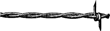
Fig. 65.—Glidden Patent Steel Two-point.
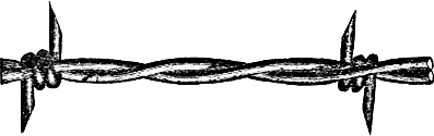
Fig. 66.—Glidden Patent Steel “Thick Set.”
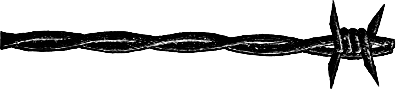
Fig. 67.—Glidden Patent Four-point.
Barb wire of nearly, if not quite all the popular kinds, is shipped from the factory on strong spools, each holding one hundred pounds in weight, or eighty rods in length. These spools are bored through the center to admit a stick or bar, which can be used as an axle in unreeling the wire. The following table shows the weight of wire required for fencing the respective areas named:
Area Length of Boundary. Weight of Wire.
1 Strand. Lbs. 3 Strand. Lbs.
1 Acre 60 Rods.67202
5 Acres⅜ Mile.167400
10 Acres½ Mile.183548
20 Acres¾ Mile.273820
40 Acres1 Mile.3651095
80 Acres1 ½ Mile.5471642
160 Acres2 Miles.7302190
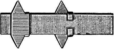
Fig. 68.—Brinkerhoff Steel Strap and Barb.
It will be observed that the larger the area enclosed, the smaller is the amount of fence required per acre. The cost of fence complete can be estimated by adding to the amount of wire indicated in the last column, the cost of sixty posts, and three and three-quarter pounds of staples, for every sixty rods. To ascertain the weight of wire required for any desired number of strands, multiply the figures of the first column of “weight of wire” by the number of strands proposed to be used.
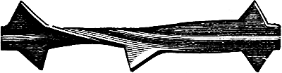
Fig. 69.—Allis Patent Barb.

Fig. 70.—Brinkerhoff Fencing Twisted.
There is a kind of barb fencing in which flat steel straps are employed instead of wire. In the form shown in figure 68, the barbs are bent around a plain strap and the whole is then galvanized, which firmly fixes the barb. Another form shown at figure 69 consists of a solid piece of steel, ribbed through the middle, and with barbs cut on both edges. These and similar forms are more expensive than wire, and are employed only in limited quantities for enclosing lawns, paddocks, etc. Still another form is like that shown in figure 70, without barbs, and twisted. This is much used to enclose lawns and ornamental grounds. It is light, neat and strong, does not harbor weeds or make snow drifts, but is comparatively expensive, as five or six strands are required to make an effective fence.

Fig. 71.—Two Strand Twisted Wire Fencing.
Still another form of unarmed fencing is shown in figure 71. It is simply the ordinary wire without barbs, and is used in limited quantities for fencing ornamental grounds, barnyards, etc.
STEEL FENCE STAPLES.
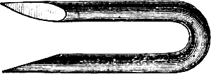
Fig. 72.—1 ¼-inch Staple.
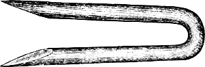
Fig. 73.—1 ¾-inch Staple.
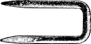
Fig. 74.—Square Top Staple For Brinkerhoff Fencing.
For fastening barb-wires to the post nothing has been found so satisfactory as staples made for the purpose from No. 9 steel wire. They are cut with sharp points to drive easily into the posts, and are of different lengths, from one inch and a quarter to one and three-quarters. Figures 72 and 73 show the usual staples for wire, and figure 74 a staple made specially for strap fencing.
HOW TO SET BARB WIRE FENCE.
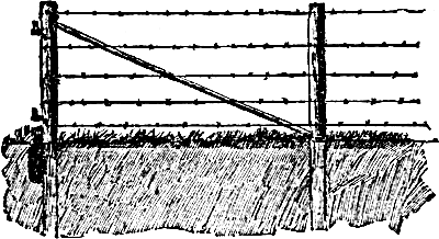
Fig. 75.—Well-braced Barb-wire Fence.
The timber for posts should be cut when the sap is dormant. Midwinter or August is a good time to cut post timber. They should be split and the bark taken off as soon as possible after cutting the timber. For end posts, select some of the best trees, about sixteen inches in diameter, from which take cuts eight and a half feet in length, splitting them in quarters for brace posts. They should be set three feet in the ground, which is easily done with a post-hole digger. When setting the brace posts, take a stone eighteen inches to two feet long, twelve inches wide, and six inches thick, which is put down against the post edgewise, on the opposite side to the brace, as seen in figure 75, putting it down about even with the surface of the ground. This holds the post solid against the brace. A heart-rail, ten feet in length makes a good brace. Put one of the long posts every sixteen or twenty rods along the line of fence, as they help to strengthen it, and set lighter and shorter posts along the line about sixteen feet apart. After the posts are set, two or three furrows should be turned against them on each side, as it helps to keep stock from the wire. Such a fence should be built of a good height. It is better to buy an extra wire than have stock injured. There is no pulling over end-posts or sagging wire.
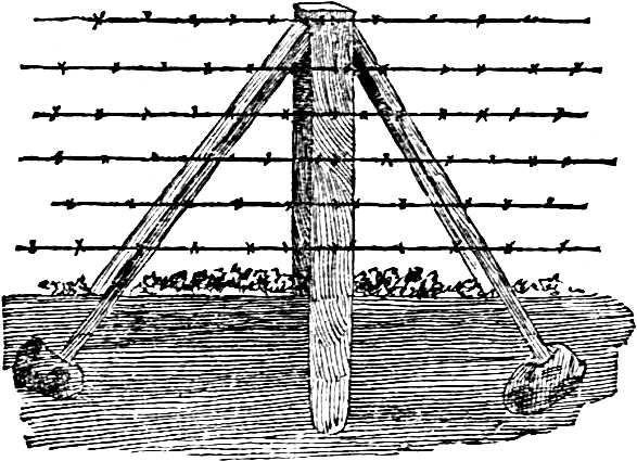
Fig. 76.—A Wire Fence Well Braced.
To make an extra solid wire fence, brace the posts, as shown in figure 76, on both sides, in order to resist the tension in either direction. Every eighth post should be thus braced, and it makes a mark for measuring the length of the fence, for eight posts set one rod apart, make eight rods, or a fortieth of a mile for each braced post. The braces are notched into the top of the posts, just below the top wire, and a spike is driven through both the brace and the post. The braces abut upon large stones which give them great firmness.
UNREELING AND STRETCHING BARB WIRE.
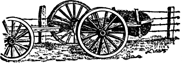
Fig. 77.—Device For Unrolling Wire.
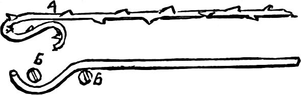
Fig. 78.—Fastening The Wire.
The general introduction of barb wire fencing has brought out a great variety of devices for handling the wire. One of these is shown in the illustrations. Two pieces of scantling are attached to the rear end of a wagon from which the box has been removed, as shown in figure 77. A slot near the end of each admits the round stick thrust through the reel of barb wire, to serve as an axle. The end of the barb wire is fastened to the fence post, the team in front of the wagon started up, and some three yards of wire unreeled. Then the hind axle of the wagon is made fast by a chain or rope to the nearest fence-post, the hind wheel nearest the fence lifted from the ground and held there by a wagon-jack or piece of board. One turn is then made in the barb wire, as shown at A, figure 78, to which is attached one end of a piece of smooth wire, some ten feet long. The other end is placed between two screws, b b, in the end of the hub, as shown in the illustration. The wire thus fastened is coiled around the hub, and the operator can tighten it and the barb wire to which it is attached, by employing the leverage of the spokes and felloes.
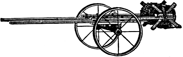
Fig. 79.—A Sulky Wire-holder.
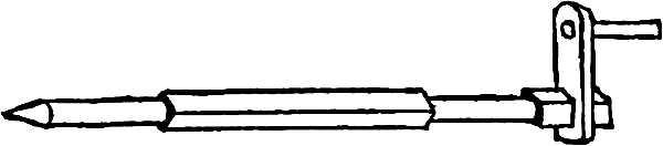
Fig. 80.—The Axle.
A lighter form of reel holder is shown at figure 79. It is made of two pieces of two by four scantlings fastened to the axle of a sulky corn plow. They must be placed far enough apart to allow the reel or spool to run between them. Make a square axle, figure 80, of some hard tough wood, rounding it where it runs in the slots of the scantling; drive it through the hole in the spool, and attach the crank. In moving fence, place the spool on the frame; remove one end of the wire from the post, fasten it to the spool, and while one man holds the pole and steers and steadies the sulky—he will have to pull back a little—another turns the spool and winds up the wire. When a corner is reached, the wire is loosened, the sulky turned, and the winding continued. When the end of the wire is reached, it is carefully loosened from the post, and firmly fastened to the spool.
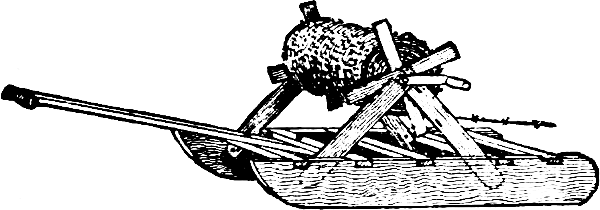
Fig. 81.—A Sled Wire-holder.
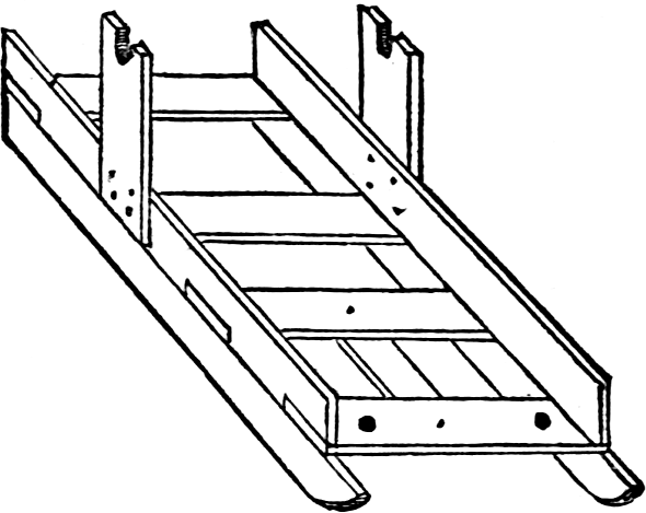
Fig. 82.—Another Sled For Wire.
It is best to have a separate spool for each wire, especially if they are of great length. The same contrivance may be used for unreeling the wire. Attach a gentle horse to the sulky, fasten the pole securely to the hames, and have a boy lead him slowly along the fence line. Once in fifty yards stop the horse, grasp the handle, move forward very slowly, and draw the wire straight and taut. If no sulky plow is at hand, a light “double-ended” sled, shown in figure 81, may be used. A man holds the short pole extending from one end, steadying and pushing a little, while the other winds the reel. The sled is drawn forward by the wire as it is wound on the reel. To unreel, attach a slow horse to a chain or rope fastened to the opposite end of the sled. A man must walk behind the horse and hold the pole to steady the sled. Managed in this way, the removal of a barbed wire fence is not at all the formidable operation that has been supposed; it can be taken down and set up again, easily, safely, and quite rapidly. Figure 82 shows another form of home-made sled, which is very useful for carrying rolls of wire for making a fence. The roll is supported on a rod, which has round ends to fit into the uprights, and which turns in the slots. When the wire is run out, the end is fastened to the clevis on the centre beam, and a notched stake, figure 83, being put under the wire, the sled is drawn up to tighten the wire, which is then stapled. This sled is useful for many other purposes, and is large enough to carry five rolls of the wire, so that by going back and forth, the whole of the fence can be put up very quickly. It is drawn by one horse, the draft chain being fastened to the front beam.
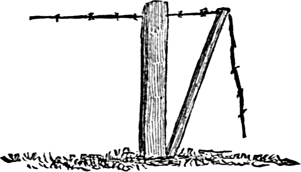
Fig. 83.—Tightening The Wire.
WIRE STRETCHERS.
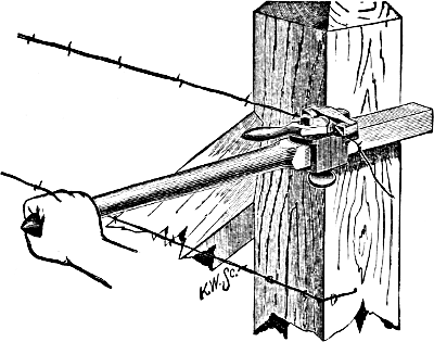
Fig. 84.—The Clark Stretcher.
For stretching barb wire there are various implements in the market, and other quite simple and effective devices can be made on the farm. Figure 84 shows the Clark stretcher and the manner of using it. Another stretcher, called the “Come Along” stretcher, figure 85, is used not only for tightening the wires, but also for handling it, in building or moving fences.
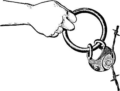
Fig. 85.—The “Come Along” Stretcher.
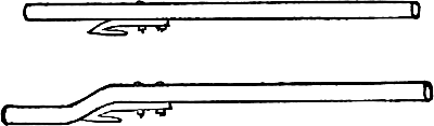
Fig. 86.—Home-made Wire-stretchers.

Fig. 87.
The useful wire-stretcher, figure 86, consists of a mowing machine knife-guard, bolted to a stout stick; one curved, as shown in the lower engraving, is preferable to a straight one, as it will not turn in the hand. When using it, the wire is held firmly in the slot, and may be easily stretched by applying the stick as a lever. Another kind of a wire-stretcher may be made of hard wood or of iron or steel bars. It consists of three pieces, two arms and a splicer, fastened together in the manner shown in figure 87, leaving a slot near one end to hold the wire. The longer arm is made immovable upon the splice by means of two or more heavy bolts, while the shorter arm is pivoted by one bolt. This allows the slot to be opened to receive the wire. The short arm is sharpened so that it may be stuck into a post, or the side of a building, if convenient. By placing this lever behind a post, one man can stretch thoroughly a long string of wire. When one man is doing the work alone, he can stretch the wire, fasten the lever back by means of a stick driven into the ground before it, and then go back and drive the staples. The short end of the lever should be about twelve inches long, and the long arm three or four feet, or even longer.
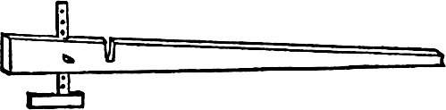
Fig. 88.—Stretcher And Gauge.
The stretcher shown in figure 88 is made of hard tough wood or iron. The wire is passed through the slot, the barbs preventing it from slipping. The arm at right angles to the lever is used to measure the distance of the strands. When the lever is set against the post, the arm rests on the strand below. By sliding it up or down, the distance between the strands is regulated.
Figure 89 shows another stretcher, that can be made by any blacksmith. The toothed cam holds the wire so that it will not slip. A block and tackle are often found useful to draw the wires with. The rolls of wire are paid out of a wagon body, and when the wire is to be drawn up, the grip is put on at any point, the tackle is attached, and one horse draws it as tight as it needs be.
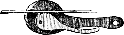
Fig. 89.—Grip For Fence Wire.
A wire fence needs frequent drawing up or it sags and becomes useless. The alternate contraction and expansion caused by change of temperature soon stretch the wire, to say nothing of other causes. The cheap and effective method employed by telegraph companies is illustrated in figure 90. It consists of a pair of grip tongs and a set of small tackle-blocks. The tongs may be made by any blacksmith, and the blocks are sold at all hardware and tool stores. An iron hook is used to couple the tongs to the block, and as the wire is drawn up, the free end of the rope may be given a turn around the same post, to hold it while the staple is tightened to hold the wire.
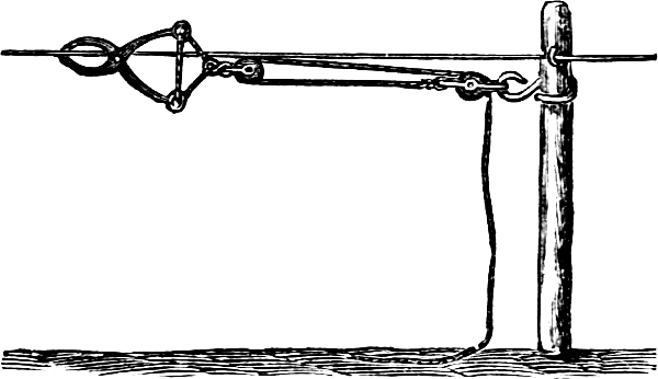
Fig. 90.
SPLICING BARB WIRES.
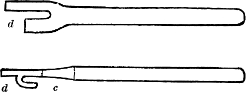
Figs. 91 and 92.—The Splicer.
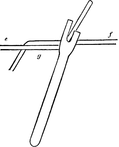
Fig. 93.—Making The Splice.
The accompanying engravings show an iron implement for splicing wire and the manner of using it. To make this splicer take a bar of half inch round iron, nine inches long. Heat about three inches of one end and hammer it flat until it is one inch wide. With a cold chisel cut a one-fourth inch slot a quarter of an inch from the right side and an inch deep, as seen in figure 91. Bend the part marked d, so that it will be a quarter inch from the flat part, as shown in figure 92. The lower part of the slot c should be about a half inch from the bend at d. Smooth with a file. To use it let e and f, figure 93 represent two wires to be joined. Bend the ends so they are nearly at right angles. Hold them with pincers at g; place the hook of the splicer on the wire, f, while the wire e falls into the slot. Twist the pieces around the wire f, when one half of the splice is made. Repeat the operation for the other end. Use about four or five inches of each wire to twist around the other. Another form of splicer, shown in figure 94, is made of cast iron, and is used in the same manner as the first. Figure 95 shows the manner of holding the wire with nippers made for the purpose, and the finished splice.
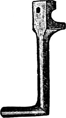
Fig. 94.
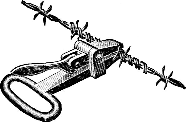
Fig. 95.
BUILDING WIRE FENCES ON UNEVEN GROUND.
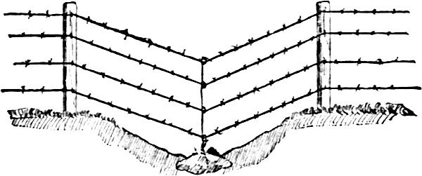
Fig. 96.—Fence On Uneven Ground.
One of the great perplexities about building wire fences on rolling ground, is how to make the posts in the hollows remain firm, for the pull of the wire in wet weather, or when the frost is coming out, lifts them and causes the wire to sag, and they cease to be an effective barrier. Posts should not be used in the lowest depressions, but in their place at the lowest spots a heavy stone should be partially sunk into the ground, about which a smooth fence wire has been wrapped, as seen in figure 96. When the fence is built, the fence wires are brought down to their place and the wire about the stone is twisted first about the lower wire, then the next, and so on to the top. This prevents the wire from raising, and does away with all trouble of the posts being pulled out by the wires. In fencing across small streams the same plan is successful.