Part 3 — APPENDIX III. Working Drawings.
Reading edition
A working drawing of an object consists of one or more views of that object so drawn that they make known the size, shape, kind of material, etc.
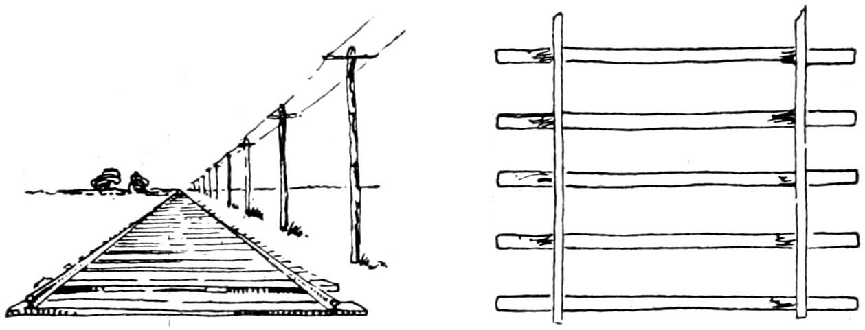
Fig. 1.
A working drawing differs from a perspective. The former represents an object as it really is, the second, represents the object as it appears. Fig. 1.
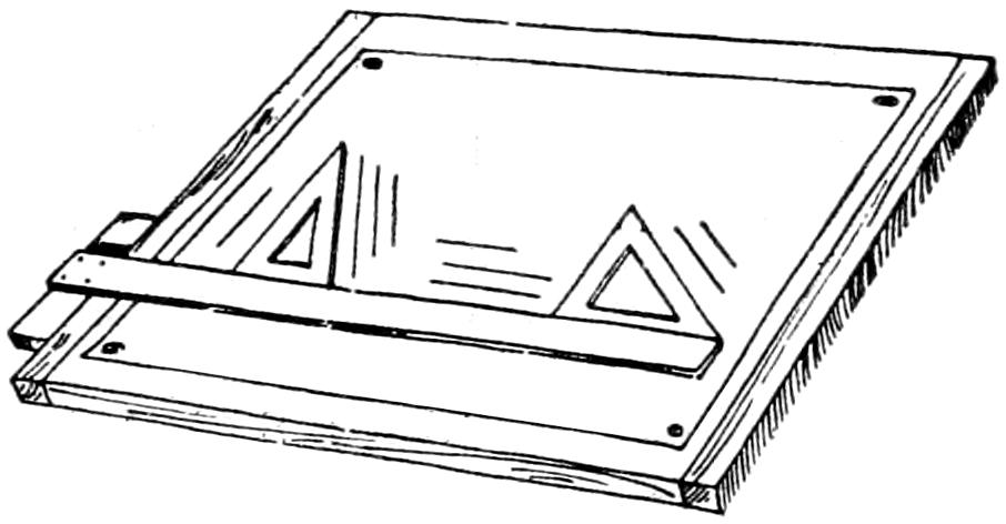
Fig. 2.
1. Instruments.
—Special instruments are required for the making of a mechanical drawing. Fig. 2 shows a drawing-board with paper fastened to it, also a T-square and the two triangles. A compass is needed for drawing circles and arcs of circles.
The T-square is used for drawing horizontal lines. The head must be held firmly against the edge of the board and the lines drawn from left to right. Vertical and oblique lines are drawn from the T-square upward, the triangles being held against the edge of the T-square which, at the same time, is held against the edge of the board.
2. Conventions.
—Since it would be impossible to make full-sized drawings of some objects—a house for instance—it is customary to use a scale and by means of it make a smaller drawing, which shall have all of its parts properly proportioned. For example, if a drawing has printed upon it “¹⁄₂ inch = 1 inch,” it means for every inch of the object the drawing is but one-half an inch. The scale is to be used for measuring only. There is quite a variety of scales. Whatever scale is used, the numbers placed upon the drawing must represent the size of the object and not of the drawing.
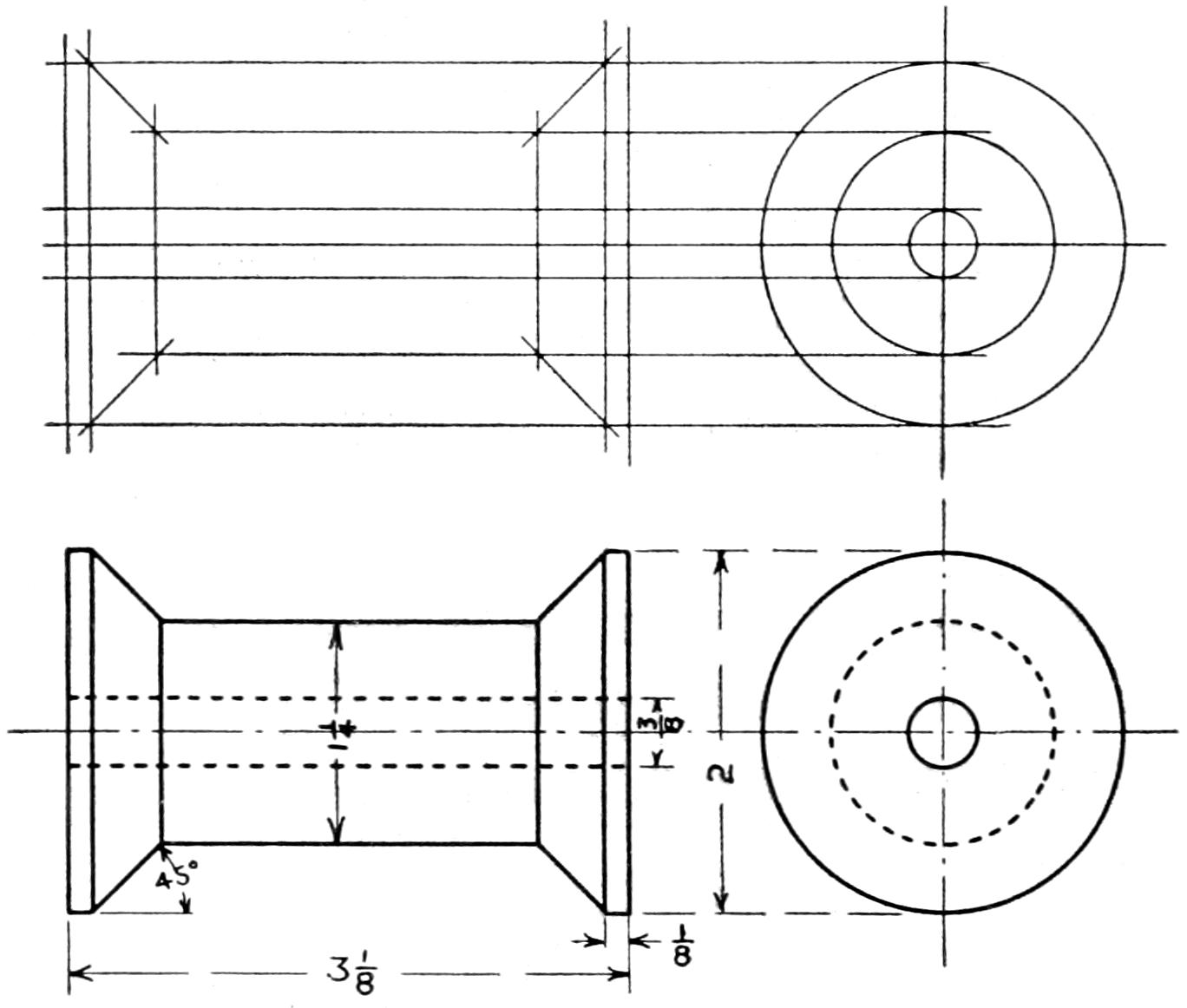
Fig. 3.
In Fig. 3 is shown a mechanical drawing of a common wood spool. It will be seen that there are different kinds of lines. Each has its meaning, as follows:
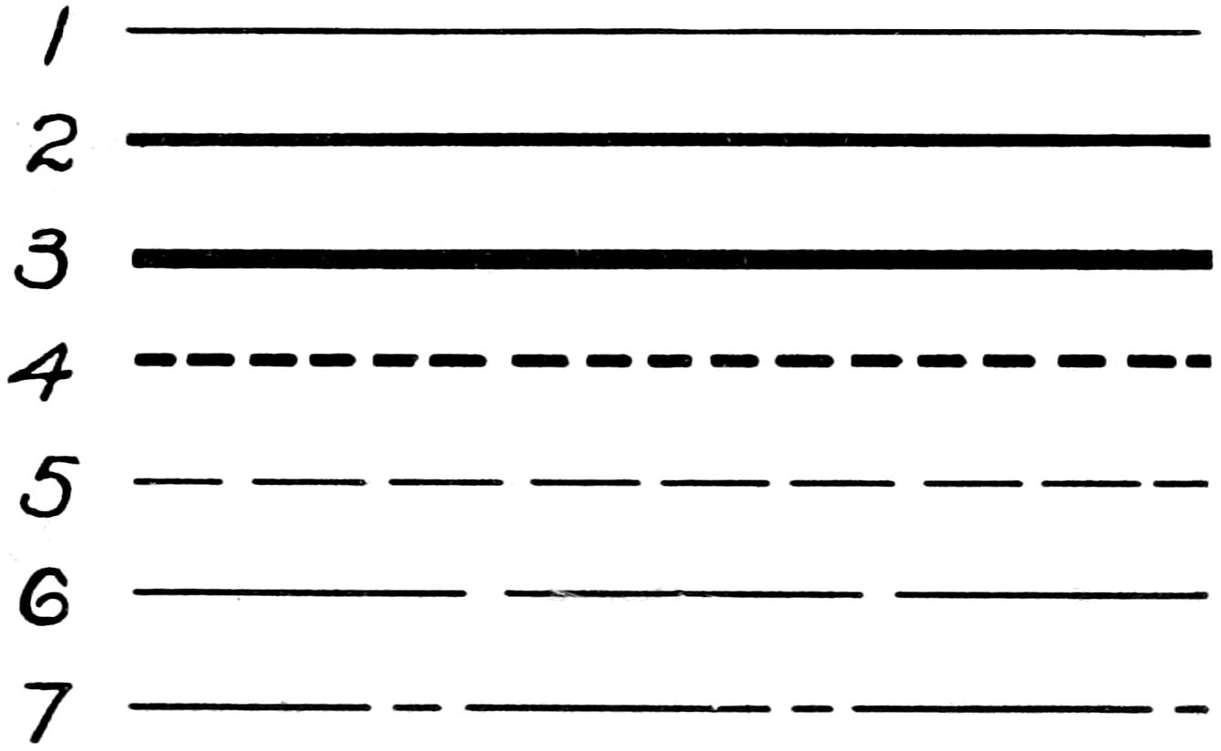
1. Light line—For penciling and cross-hatching.
2. Full line—For visible outlines of objects and limits of parts.
3. Heavy line—For border lines.
4. Dot line—For invisible outlines of objects and limits of invisible parts. Same width as 2.
5. Dash line—For projection lines. Same width as 1.
6. Long dash line—For dimension lines. Same width as 1.
7. Dot-and-dash line—For center lines and section lines. Same width as 1.
When there is not room for the figures that represent dimensions, the arrow heads may be turned in the direction of the measurement and placed outside. The figure, too, may be placed outside if necessary.
Nothing but the letters, the figures and the barbs—not the shafts—of the arrow are drawn free-hand.
Sometimes, it is desirable to have one dimension shorter than the scale selected would allow; this is done by means of a broken view: Fig. 4. The figured dimension prevents confusion.
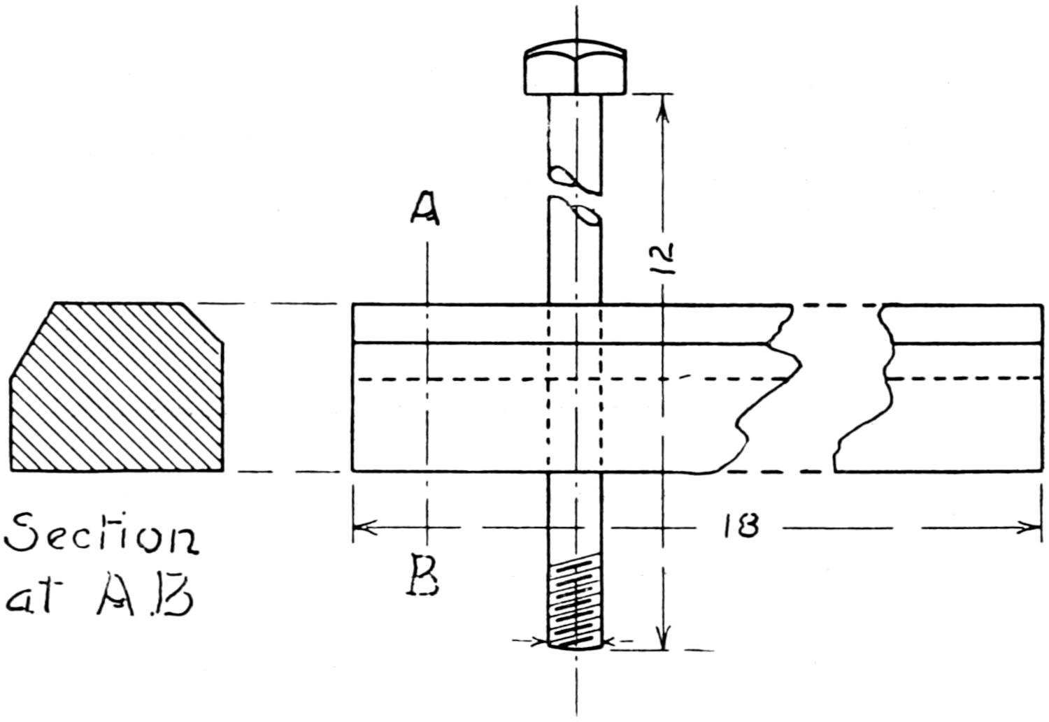
Fig. 5.
Fig. 4.
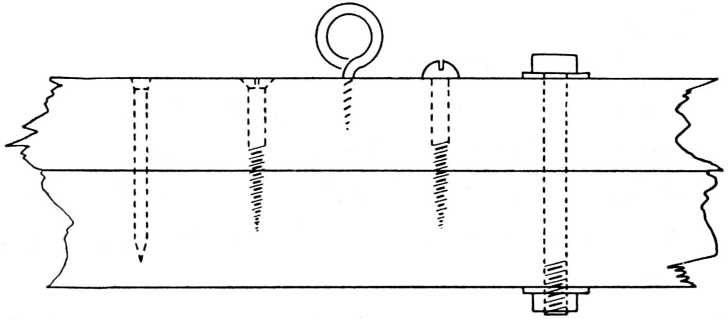
Fig. 6.
In Fig. 5, is shown a sectional drawing. Sectional drawings represent an object as it would appear if cut, with the part nearer the worker removed. Sections are indicated by “cross hatching,” the lines being equally spaced and drawn at an angle of 45 degrees.
Screws and nails are represented as in Fig. 6.
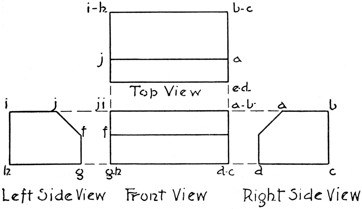
Fig. 7.
3. Projection and Relation of Views.
—The names and the relative positions of three views are shown in Fig. 7. From these it will be seen (1) that the different views are arranged with reference to the front view, so that the part of a side view which is nearest the front view represents a part of the front of the object, (2) that the corresponding horizontal measurements of top and front views are alike, (3) that the corresponding vertical measurements of front and side views are alike, (4) that the corresponding vertical measurements of the top view and horizontal measurements of a side view are alike.
4. Letters and Figures.
—Letters are usually made freehand, light ruled lines at the top and bottom acting as guides. A simple style of letter and figure is shown in Fig. 8. They are placed in spaces that the proportion of the parts may the more readily be seen. They may be narrowed or widened by changing the width of the spaces, and shortened or lengthened by changing the height of the spacer.
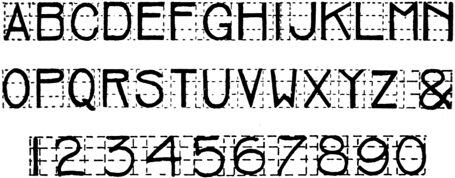
Fig. 8.
5. Constructions.
—The hexagon, or six-sided figure; the octagon, or eight-sided figure; and the ellipse are so very frequently used in simple woodwork, that their construction is given here.
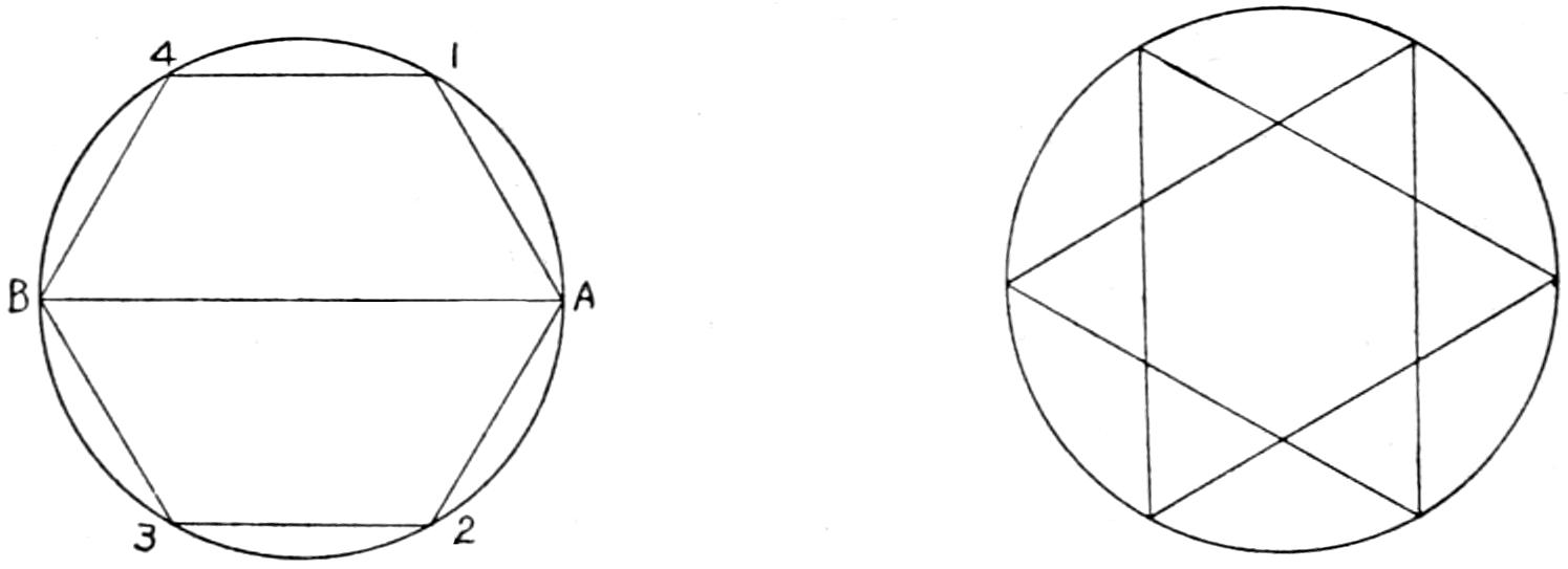
Fig. 9.
Directions for hexagon, Fig. 9: Describe a circle of a size equal to the required distance of hexagon from corner to corner. Draw the diameter A-B. With the point A as a center, using the radius of the circle, cut the circle at 1 and 2. With B as a center, and the same radius, cut the circle at 3 and 4. Connect A-1, A-2, 2-3, etc. Connecting every other point, as A-3, 2-B, etc., makes a six-pointed star.
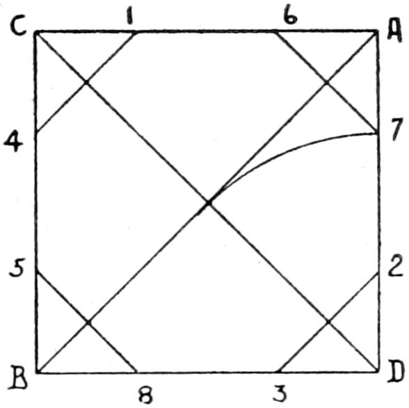
Fig. 10.
Directions for octagon, Fig. 10: Draw a square with a width equal to the desired width of the octagon from side to side. Draw the diagonals. With the points A, B, C, and D as centers and a radius equal to one-half the diagonal, cut the sides of the square at 1, 2, 3, 4, 5, 6, 7, 8. Connect these points as shown.
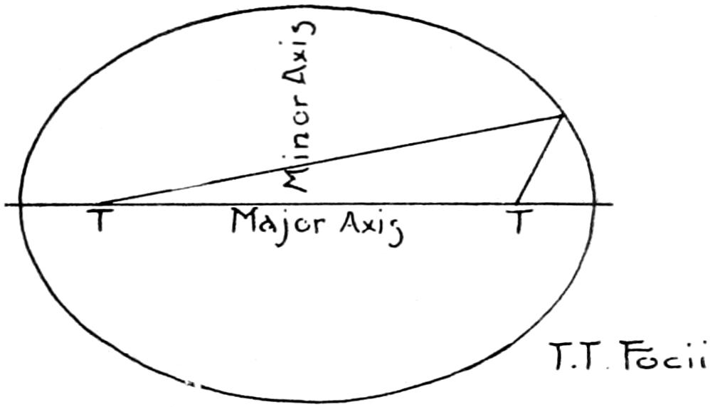
Fig. 11.
Directions for ellipse, Fig. 11: An ellipse is a curve such that the sum of the distances from any point on it to two fixed points called the focii shall always be the same.
An easy way to construct such a curve is to place two thumb tacks at the focii, attach the ends of a string to them. With a pencil moving freely in the string but holding it taut draw the curve. By moving the tacks farther apart or closer together and by lengthening or shortening the string, the size and shape of the curve may be changed as desired.
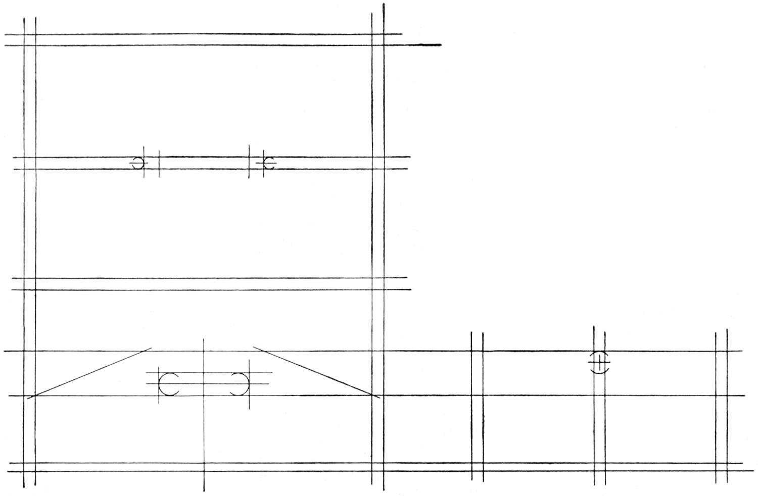
Fig. 12.
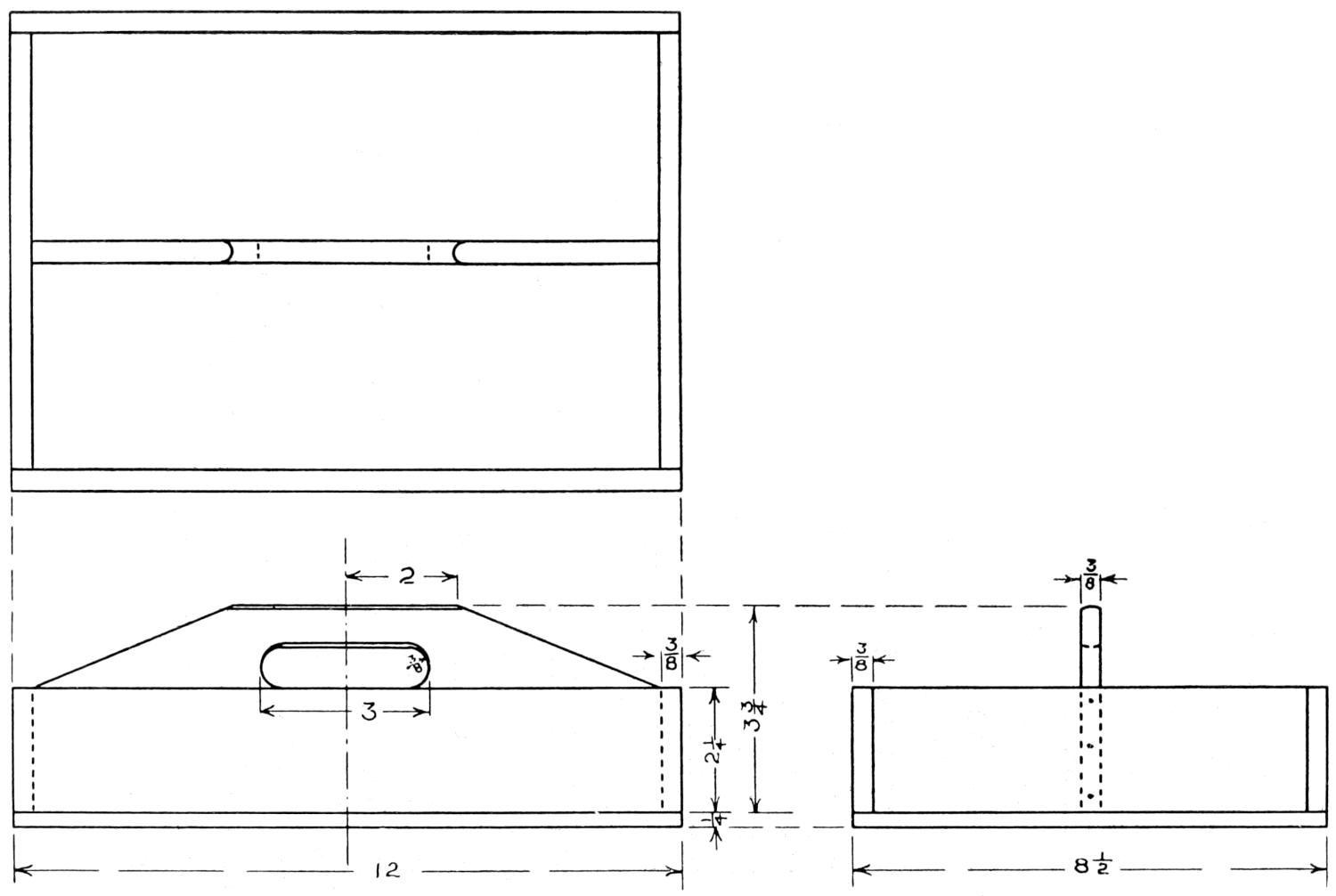
Fig. 13.
6. Order of Procedure.
—Beginners should strive to know and to acquire good practice in drawing. Before beginning see that the pencil is properly sharpened.
(1) Determine the size and spacings of the views so that the parts of the drawings may be properly placed.
(2) With light full lines block out the different views. Blocking-out lines are made of indefinite length and the proper distances marked off on them after they are drawn. Holding the rule or scale upon the drawing vertically, mark off the vertical spaces. Draw light lines thru these points. Upon one of these horizontal lines lay off the horizontal spaces. Draw light vertical lines thru these points. Fig. 12.
(3) Put on the dimensions.
(4) Put on the lettering.
(5) The drawing is ready for inking. In blocking-out, all lines are made full, light. In inking, the different kinds must be represented properly. Fig. 13. If it is not to be inked go over the lines that represent edges with the pencil a second time so that the outlines of the object will “stand out.”