Front matter
Reading edition
Elements of Trench Warfare
Waldron
Elements of Trench Warfare
Bayonet Training
By
Lieut. Colonel William H. Waldron
29th U.S. Infantry
DISTINGUISHED GRADUATE INFANTRY AND CAVALRY SCHOOL, 1905 GRADUATE ARMY STAFF COLLEGE, 1906 GRADUATE ARMY WAR COLLEGE, 1911 ASSISTANT DIRECTOR ARMY WAR COLLEGE COURSE, 1911-12
Author of
"Scouting and Patrolling" "Tactical Walks"
PUBLISHED BY
EDWIN N. APPLETON
1 Broadway, New York
1917
Price 75 Cents, postage paid
Copyright, 1917, by William H. Waldron
First Edition, 5,000, March 1st, 1917. Second Edition, 10,000, August 1st, 1917. Third Edition 30,000, September 25th, 1917.
PRESS OF ISAAC GOLDMANN COMPANY, NEW YORK
NOTICE
There is a wealth of material in this little book that will interest the soldier. From the illustrations alone he will be able to obtain a good general idea of the subject.
It is essentially a soldier's book, written in language that he can understand. The price has been kept within the limits of his pocketbook.
With a view to securing a wide distribution of the book I desire to secure a representative in every organization in the Army. I have an attractive proposition to make to competent parties.
A letter will bring particulars. My address will be found in the Army List and Directory. If this is not available, a letter addressed as follows will be forwarded to me:
Captain W.H. Waldron, 29th Infantry, Care of "Infantry Journal," Washington, D.C. (Signed) W.H. Waldron.
CONTENTS
Page
Chapter I.—The Organization of a Section of the Position 9
Chapter II.—Obstacles: Construction, repair. Wire entanglements, barricades, land mines, inundation 13
Chapter III.—Lookout and Listening Posts: Types. Construction, service 27
Chapter IV.—Field Trenches: Traversed trenches. Types of trenches. Drainage. Communication trenches. Dugouts. Penetration of projectiles. Communication. Trench mortar positions. Machine guns. Supporting points 33
Chapter V.—Use and Improvement of Natural Cover 60
Chapter VI.—Revetments: Sandbags. Fascines. Hurdles. Gabions 74
Chapter VII.—Working Parties: Details of organization. Laying out tasks. Operations 90
Chapter VIII.—Grenade Warfare: Organization and tactics of grenadiers. Offensive operations. Clearing fire trenches. Clearing communication trenches. Night operations. Grenade patrols. Notes on grenade warfare 97
Chapter IX.—Gas Warfare: Methods of dissemination of gas. Gas helmets, care and use of Sprayers 118
Chapter X.—Service in the Trenches: Preparations for entering. Inspection of trenches. Tactical dispositions. Going into the trenches. Information routine. Observation field glasses. Snipers. What to fire at. Use of rifle grenades. Scouting and patrolling. Care of arms. Care of trenches. Latrines. Maps. Frost bite. The trench soldier's creed 128
Chapter XI.—The Attack in Trench Warfare 162
BAYONET TRAINING
Features of the Bayonet 175
Method of Carrying out Bayonet Training and Hints to Instruction 177
BAYONET LESSONS
Formation—Technique of Instruction 180
Lesson No. 1—
Position of "Guard" 181
" " "Rest" 184
" " "High Port" 184
" " "Long Point" 184
The "Withdrawal" After a Long Point 189
PROGRESSION
Vulnerable Parts of the Body 190
Lesson No. 2—"The Parries" 192
PRACTICE 194
Lesson No. 3—"The Short Point" 193
Lesson No. 4—"The Jab or Upward Point" 197
METHOD OF INJURING AN OPPONENT
Butt Strike I. 200
" " II. 200
" " III. 200
" " IV. 202
Practice 202
TACTICAL APPLICATION OF THE BAYONET 203
THE BAYONET ASSAULT 203
METHOD OF CARRYING THE RIFLE WITH BAYONET FIXED 205
TEAMWORK 206
THE ADVANCE 206
THE CHARGE 206
ASSAULT PRACTICE 208
FINAL ASSAULT PRACTICE 209
ACCESSORIES 211
TARGETS 215
CONSTRUCTION OF GALLOWS 216
" " DUMMIES 217
" " "TURK'S HEAD" 218
" " PARRYING DUMMY TARGET 218
DISCS ON TARGETS 218
EXERCISES
Exercise 1 221
The Run 222
Exercise 2 223
INTRODUCTION
This little book has been prepared with a view to placing before the soldier a store of information on the subject of Trench Warfare as it has been developed on the battle fronts of Europe, and giving him some idea of the nature of the service that he will be called upon to perform when the time arrives for him to do his "bit."
The illustrations have been carefully prepared and arranged to the end that the soldier may gain a fair knowledge of the subject from them alone. The text is intended to treat the subject in a purely elementary manner that the soldier may be able to understand.
The size of the book is such that it may be conveniently carried in the pocket and referred to as occasion requires. The price has been kept down to the point where it is available to the soldier.
If the book assists in his preparation for the front and, by reason of the knowledge that he has gained from it, helps to make him more efficient when he gets there, it will have served its purpose.
The Author.
Chapter I
ORGANIZATION
The normal organization of an intrenched position includes the following elements from front to rear:
1. In front of the position and at a variable distance from the first line fire trench there is a line of wire entanglements. (See Obstacles, p. 13).
2. Close up to the wire entanglements there is an intrenched post known as the "listening post," which is connected with the first line fire trench by a zigzag communicating trench. (See Listening Posts, p. 27).
3. Then comes the first line fire trench with attached machine-gun emplacements at convenient points. (See Fire Trench and Machine-Gun Emplacements, pp. 33 and 54).
4. The fire trench is so narrow that lateral communication along it is effected only with difficulty. In order to provide a passageway a communication or supervision trench is provided a few yards in rear of the fire trench. Passageways lead from this communication trench to the fire trench and to the dugouts located along it.
5. At a variable distance in rear of the fire trench (100 to 200 yards) the emplacements for bomb-throwing apparatus and trench mortars are located. These are connected up laterally by a communication trench which joins with the main communication trench running from front to rear through the position. (See Emplacements for Trench Mortars, p. 51).
6. From 100 to 400 yards to the rear of the first line fire trench, and generally parallel to it, is the supporting trench or cover for the supports. This trench is invariably provided with strong overhead cover and a system of dugouts for the protection of the troops. (See Cover for Supports, p. 53).
7. This whole arrangement of trenches is connected throughout from front to rear, and laterally, by a system of zigzag communication trenches.
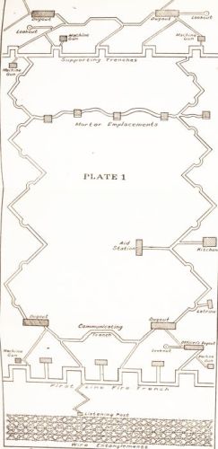

PLATE 1. PLAN OF THE ORGANIZATION OF AN INTRENCHED POSITION
Take this brief description together with Plate 1, the drawing that accompanies this volume, and study the two until you get the entire system fixed firmly in your mind; that is, until you get a mental picture of all the elements included in the system.
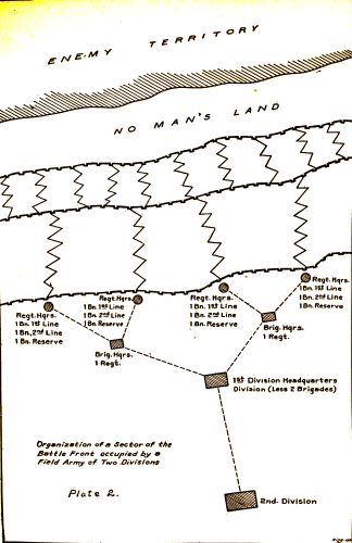
Organization of a Sector of the Battle Front occupied by a Field Army of Two Divisions. Plate 2.
After you have done this, study on through the book in order that you may know the purpose of each of these elements and how one links up with the other.
This is the typical system now in use in the European war theaters. Circumstances at certain places may render some variations necessary, and it must not be inferred that the trace of the works is the same throughout. As a rule the types of trenches (altered when necessary to meet local conditions) illustrated herein are the ones in actual use on the war fronts.
All of these trenches and their accessories constitute what is known as the first line. At a distance of from 2,000 to 5,000 yards in rear of this first line a second line, organized in a similar manner, is to be found.
At intervals of from 800 to 1,500 yards along the first line-centers of resistance, or what we know as "supporting points," are located. These consist of fortified villages, or a network (labyrinth) of trenches, provided with every defensive device known to modern warfare. The object of these supporting points is to bring a flanking fire to bear on the intervals between them, with the idea that an attacking force cannot advance beyond them without capturing them.
Plate 2 shows the general scheme of the occupation of a sector of the line by a field army of two divisions.
Chapter II
OBSTACLES
The element of the defensive line nearest the enemy is a line or series of lines of obstacles which are designed for the purpose of:
1. Protecting the lines from surprise.
2. Reducing the momentum of the attack, by breaking up the unity of action and cohesion.
3. Holding the enemy under the effective fire of the defenders.
The conditions that obstacles should fulfil are as follows. They must—
1. Be close to the defender's position. As a rule on the western front they are not more than from 50 to 100 yards distant. If they are too close it may be possible to throw hand grenades from the far edge of them into the defender's trenches.
2. As far as practicable, be sheltered and screened from the enemy. Shell fire is the most effective method of destroying obstacles. If they are not concealed they may furnish aiming points for the enemy's fire against the first line fire trench by his being able to estimate its location with reference to the obstacle.
3. Afford no cover or screen to the enemy.
4. Be so placed that the enemy will come upon them as a surprise.
5. Be so constructed as to be difficult of removal under fire and impracticable to negotiate while still reasonably intact.
6. Be arranged so as not to interfere with a counter attack. The obstacles may have occasional gaps left in them which may be mined.
The different classes of obstacles are: Abatis, low wire entanglements, high wire entanglements, barricades, mines, fougasses, crows feet, military pits with wire entanglements, inundations, etc.
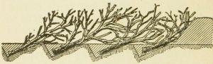
Plate 3.—Abatis.
Abatis (pronounced abatee) consists of branches of trees lying parallel to each other, butts pointing to the rear, and the branches interlaced with barbed wire. All leaves and small twigs should be removed and the stiff ends of branches pointed. The butts are staked or tied down or anchored by covering them with earth. When more than one row is used the branches overlap the butts of those in front so as to make the abatis about 5 feet high. An abatis formed by felling trees towards the enemy, leaving the butt hanging to the stump, is called slashing.
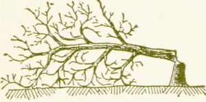
Plate 4.—Slashing.
Wire Entanglements
Barbed wire is the material most employed in the construction of obstacles. It may be used in the following manner:
1. As a simple trip, for giving the alarm. It is stretched just above the ground and attached to some object that will cause a noise to be made if molested.
2. A simple wire fence, to cause delay and confusion to the enemy in his advance.
3. As an adjunct to tree and brushwood entanglement.
4. As a wire entanglement.
5. As a covering for portable cylinders.
The advantages of the barbed-wire entanglement are:
1. It is easily and quickly made.
2. It is difficult to destroy.
3. It is difficult to get through.
4. It offers no obstruction to the view and fire of the defense.
The low wire entanglement is constructed as follows:
1. Drive stakes in the ground until they project about 18 inches. The stakes should be about 6 feet apart, those in each row being opposite the intervals in adjacent rows.
2. The wire is then passed loosely from the head of one stake to another, wound around each and stapled.
3. Where two or more wires cross they should be tied together.
A more useful and efficient modification of the low wire entanglement is made by stapling the wire down the sides of the stakes, allowing five or more feet of slack wire between stakes. Drive the stakes in the ground until the top is flush. This results in a loose network of tangled wires difficult to get through, easily concealed and difficult to remove.
The high wire entanglement is made by driving stakes so that they protrude from 4 to 6 feet above the ground. They are placed at irregular intervals 5 to 8 feet apart. The head of each stake is connected with the foot of adjoining stakes with the wire loosely drawn, wound around the stakes and stapled fast. Each center post should be stayed by four wires. There should be a trip wire about 9 inches from the ground all the way across the front and another about a foot from the top of the center posts. Barbed wire may then be hung in festoons throughout the entanglement, with no fixed pattern. To increase the entanglement wire may be stapled to the foot of the posts, as indicated in the paragraph above, before they are driven. Large nails should be driven in the tops of the posts with half their length protruding. A number of the wires in the entanglement should be fastened together where they cross. The wire should be passed through paint, if practicable, to take away the bright color. The post should be painted the color of the surrounding country. Under the conditions encountered on the western front this work has to be done hastily. It is best, therefore, to limit the first stage of construction to just so many strands as will form a nucleus for the whole entanglement, in order that the area may be covered by an obstacle before interruption occurs.
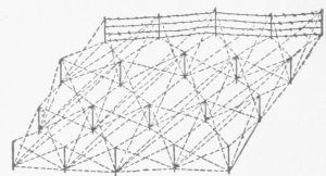
Plate 4a.—Plan of wire entanglement.
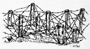
Plate 5.—High wire entanglement.
Tight wires help the enemy's advance by forming supports for hurdles. It must be constantly borne in mind that the wires must not be stretched taut.
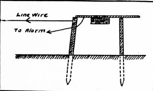
Plate 5a.—Alarm trap.
A portable wire entanglement is constructed by stretching wire loosely around a wooden framework, either circular or square or made on a knife rest, and rolling it into position to close up gaps that may have been made in the entanglement. The illustration shows the wooden framework.
The ordinary repairs to entanglements are made under cover of darkness by working parties detailed for the purpose. Iron posts that can be quickly placed in position are advantageous, their disadvantage being that they may retard bullets that would go through the ordinary wooden posts, thus furnishing just that much cover and protection to attacking parties.
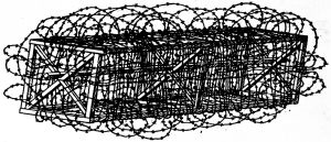
Plate 6.—Portable entanglement. Constructed in the trenches and rolled into position.
In the construction and repair of entanglements care must be taken to see that they are firmly fastened into the ground with numerous stay posts or "deadmen." This is to prevent the enemy from pulling them to pieces with grappling hooks connected to ropes that lead to his trenches and are attached to powerful windlasses or capstans.
Barricades
Barricades are employed for the defense of streets, roads, bridges, etc. They may be made out of any available material such as furniture, vehicles (overturned or with wheels removed), carts filled with stones, bales of goods, etc.
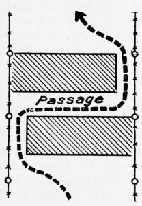
Plate 7.—Plan of barricade for blocking a road.
Where trees grow along the roadside they may be felled across the road. If necessary, barbed wire may be run through the branches to make the passage more difficult.
Barricades should not as a rule close the road entirely to traffic. Passages are required to allow the defenders to pass through when it is necessary to do so. Hence they should be made in two parts, one overlapping the other, as shown in the illustration.
A fougass is a mine so arranged that upon explosion a large mass of stones is projected against the enemy. An excavation is made in the shape of a frustrom of a cone, inclining the axis in the direction of the enemy so as to make an angle with the horizon of about 45 degrees. The sides splay outward slightly. A box of powder is placed in a recess at the bottom. This is covered with a platform of wood several inches thick, on which the stones are piled.
The fuse is placed in a groove cut at the back of the excavation, or the mine may be exploded by means of electricity.
The line of least resistance for the charge must be arranged so that the powder will act in the direction of the axis and not vertically. This is accomplished by throwing the excavated earth on the crest towards the defender's side and ramming it well.
To ascertain the powder charge for any fougass, divide the number of pounds of stone in the charge by 150. This gives the number of pounds of powder in the powder charge. Thus a fougass charged with about 70 pounds of powder will throw about 5 tons of stone over a surface about 160 yards long and 120 yards wide.
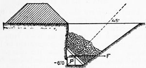
Plate 8.—Fougass.
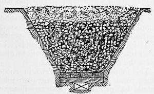
Plate 9.—Vertical fougass.
When broken up a cubic foot of stone weighs about 100 pounds.
A vertical type of fougass is also shown. A charge of 25 pounds of powder should scatter a cubic yard of stones over an area about 200 by 100 yards.
Small Land Mines
Land mines are placed in the line of the advance of the enemy and exploded either by electricity or fuse from the defense. They are made by digging holes from 2 to 3 yards deep, either by excavation or by boring. In the former case the charge is placed in a recess which extends into the solid earth at the side of the hole, which is then refilled and tamped. In the latter case the charge is placed in the bottom of the hole, which is then refilled and solidly tamped. In common earth the powder charge for a 2-yard hole is 25 pounds. That for a 3-yard hole is 80 pounds. The diameter of the crater formed will be about twice the depth of the charge.
The mines may be arranged in one or more rows. The intervals between mines should be such that the craters will nearly but not quite join. The position of the mines should be concealed as much as possible and further sophisticated by disturbing the ground slightly at points where there are no mines and so situated as to suggest a systematic arrangement.
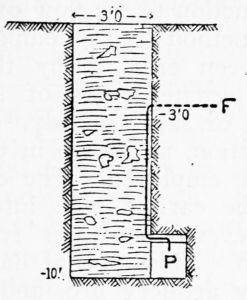
n: Plate 9a.—Land mine. F, Line from powder charge to battery. P, Powder charge.
Inundation
Backing up the water of a stream so that it overflows a considerable area forms a good obstacle, even though of fordable depth. If shallow, the difficulty of fording may be increased by irregular holes or ditches dug before the water comes up, or by constructing wire entanglements in the water. It may be employed with advantage when the drainage of a considerable area passes through a restricted opening, as a natural gorge, culvert or bridge.
Open cribs filled with stones, or tighter ones filled with gravel, may form the basis of the obstruction to the flow of the water. The usual method of tightening spaces or cracks between cribs is by throwing in earth or alternate layers of straw, hay, grass, earth, or sacks of clay. A continuous construction, as shown in the illustration, may be employed. The ends of the dam must be carried well into the solid earth to prevent the water from cutting around them. This type of dam is easily destroyed by artillery fire, and cannot be depended upon.
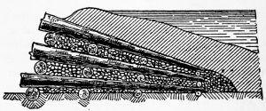
Plate 10.—Dam construction.
Chapter III
LOOKOUT AND LISTENING POSTS
Except when the garrison are actually required to man the parapet, they will be kept under cover, with the exception of a few lookouts, whose duty it is to give timely warning of the movements of the enemy.
When the opposing forces are in close proximity to each other mining operations are generally resorted to by both sides to compass the destruction of the opposing works and open the way for an attack.
Lookout and listening posts serve the double purpose of having a few men at the most advantageous places for observation at the front and flanks and providing points at some distance to the front of the first line fire trenches from which listeners may be able to discover the location and direction of enemy mining operations before they really menace the fire trench.
In the normal case there will be some natural cover available. Such, however, is not always the case, and specially constructed observation stations have to be provided.
The posts should be placed in advance of the first line trench, the distance depending upon circumstances which have to be determined in each particular instance. They must be fully protected from reverse fire so that there will be no chance of the observer masking the fire of his comrades manning the fire trench.
Unless the ground is very favorable it will be found difficult to provide for observation above ground. Where there are natural features such as embankments, mounds, hedgerows, ruins of buildings, etc., it may be possible to make provision for observation even by day.
Where a loophole is used, the type having the narrower end outward should be provided.
In the open type of post the observation directly to the front may be greatly facilitated by the use of the periscope. (Plate 11.)
A good, strong parapet thrown up and chopped off at the corners will enable the observer to cover areas from an oblique direction from the post and protect him from fire from the front.
In the covered type the observer is provided loopholes having the splay towards him. These may also be constructed to the oblique rather than to the front. When this is done, provision must be made to cover the entire front of the position from the several posts. (Plate 12.)
The post may be connected with the first line fire trench by a narrow zigzag trench or by an underground passage. If the former, it must be thoroughly concealed and have no excavated earth visible. If it can be located along a hedge or some other natural feature its location may remain unknown to the enemy for a considerable length of time. Where a communication gallery is constructed the roof and walls must be suitably shored up by casing and supports.
The sentinel in the listening post carries no accouterments. It has been found that the creaking noise made by equipment when the sentinel moves has been taken for mining operations of the enemy by his comrades.
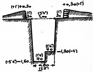
Plate 11.—Open type of listening post.
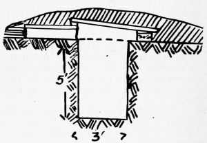
Plate 12.—Covered type of listening post.
Listening galleries should never be left without a sentinel. There should be a depot of arms and hand grenades near the entrance to the gallery in case men are attacked while on duty from either above or below ground.
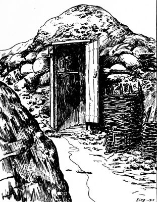
Plate 13.—A listening and observation post.
Listening will be conducted at specified times, or on some prearranged signal, and for a definite period. During this time all within the listening area, including the trenches, must remain absolutely motionless.
Infantry manning a trench can assist listening by digging a small pit, 6 feet deep below the trench, and running a bore-hole out 20 feet or more.
The enemy is always listening for indications of the direction and position of gallery heads. Work must therefore be carried on with a minimum of noise. Shouting down the shafts of galleries is absolutely forbidden.
When the mining operations of the enemy are detected a report should be made at once to the officer in charge of that section of the trench.
Chapter IV
FIELD TRENCHES
The next element of the defensive position is the first line fire trenches. These are located so as to have a good field of fire to the front for several hundred yards and so constructed as to give the greatest cover and protection from the fire of the enemy.
An unbroken, continuous trench would be exposed to enfilade fire. A shell, shrapnel or grenade bursting therein would have widespread effect. To overcome these elements the trench is constructed in short lengths, with traverses between them, and technically known as the traverse type.
Better defilade is thus secured and the material effect of any burst is confined to narrow limits.
The trench interval between the traverses is known as the "bay," which should not ordinarily be longer than 18 feet. Longer bays invite heavy casualties in case the trench is enfiladed or a high explosive shell finds its mark.
The illustration, Plate 14, shows a trace of the traversed type of fire trench.
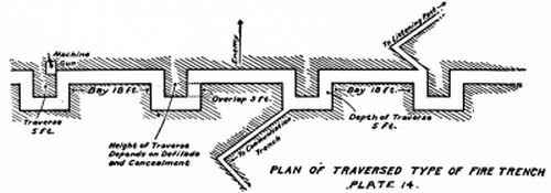
PLAN OF TRAVERSED TYPE OF FIRE TRENCH PLATE 14. 1. Length of bay, 18 feet. 2. Width of traverse, 5 feet. 3. Length of traverse, 5 feet. 4. Overlap of traverse, 3 feet. 5. Height of traverse depends upon defilade required and practicability of concealment.
Type of Trench
Formerly, protection from the enemy's fire was obtained by thickness of parapet. In the trench warfare of today it is obtained by completely concealing the riflemen in a deep, narrow trench with a very low parapet.
The height over which the average man can fire is about 5 feet or about five-sixths of his own height. This factor determines the height of the parapet above the firing banquet of the trench or the height of bottom of loophole above the same point, when the latter is employed.
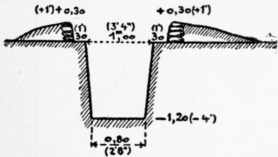
Plate 15.—Simple standing trench. 1. Width at top, 3 feet 4 inches. 2. Width at bottom, over all, 2 feet 8 inches. 3. Width of firing banquet, 1 foot 4 inches. 4. Height of parapet above firing banquet, 5 feet. 5. Height of parapet above bottom of trench, 6 feet 4 inches.
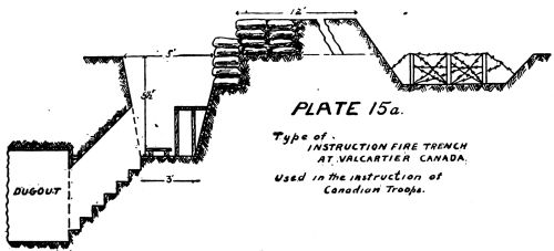
PLATE 15a. Type of INSTRUCTION FIRE TRENCH AT VALCARTIER CANADA. Used in the instruction of Canadian Troops.
The type of trench in general use today is the simple standing trench shown in Plate 15.
Drainage
If a trench is to be occupied for any length of time, especially if much ground or falling water is to be encountered, drainage becomes of prime importance. Many years ago a celebrated military authority asserted that "nothing so saps the courage of a soldier as to wet the seat of his breeches." This may be accepted as a true maxim, especially in cold weather. The trench should therefore be made as dry as possible. The floor of the trench should be given a sufficient slope to the rear where an intercepting drain should carry the water to prepared sumps or to a point from which it can be disposed of by drainage. Provision should also be made to exclude surface drainage from the trenches.
A scheme for trench drainage is shown in the illustrations (Plates 16, 17 and 18).
Overhead cover may be provided as shown in Plates 19 and 20.
Loopholes are made wherever head cover is provided. Where the enemy's trenches are close, there is considerable danger in using them. Collective firing takes place over the parapet. When loopholes are used they should face half-right or half-left and not directly to the front.
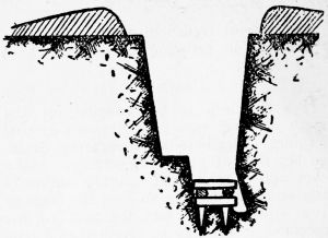
Plate 16.—Method of draining trench.
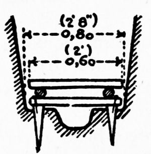
Plate 17.—Details of trench drainage.
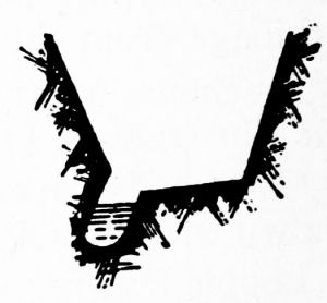
Plate 18.—Detail of trench drainage.
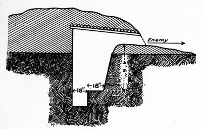
Plate 19.—Overhead cover.
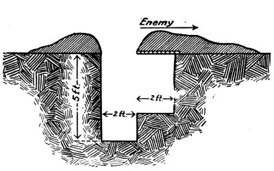
Plate 19a.—Overhead cover.
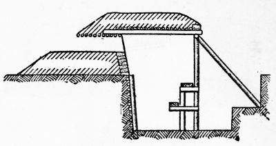
Plate 20.—Overhead cover.
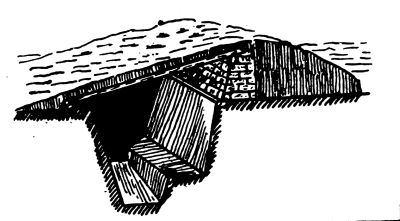
Plate 20a.—Overhead cover.
The disadvantages of loopholes are:
1. The difficulty of concealing firing points. Loopholes give the enemy's snipers an easy mark.
2. They lessen the number of rifles that can be used at a given point.
3. The necessary head cover makes it difficult to get out of the trench quickly.
4. Damaged head cover often spoils a good firing point.
The three types of loopholes are:
1. Narrowest point of the opening nearest the marksman. This type is most difficult to conceal, much of the parapet thickness is cut away and, if of hard material, tends to deflect the bullets into the firer's face. This defect may be remedied somewhat by stepping the surface of the loophole.
2. Narrowest point to the front. Easiest to conceal but gives a limited field of view.
3. Narrowest point midway between the front and rear. A compromise between the first two types.
The following general remarks on the construction of loopholes are taken from a work based upon the experience gained during the war in Europe:
1. The angle of splay is usually 60 degrees. The thicker the parapet the smaller must be the angle of splay.
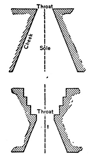
Plate 21.—Types of loopholes.
2. The marksman holds his rifle in a line connecting the right shoulder, the eye and the object, hence most of the body lies to the left of the rifle. The loophole should be made to the right, with a niche in the wall of the parapet from the hip to the armpit, to bring the left shoulder well forward. It will be found that this permits the right elbow to be placed on the edge of the parapet.
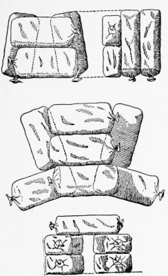
Plate 22.—Methods of constructing loopholes with sandbags.
3. Box loopholes with screens or blindage may be used, but should be placed by a skilled marksman. The great disadvantage is that the enemy notes these parapet alterations. Steel loophole plates are now provided for this type of loophole. As the Germans sometimes use a steel bullet with great penetrating power, it is advisable to place two plates together to insure protection.
4. With every precaution that may be taken it is difficult to conceal a loophole. A good plan is to deceive the enemy by using painted sandbags and preparing plenty of dummy loopholes.
5. The minimum width of loopholes should be 2½ inches. If narrower than this, it is impossible to use both eyes to judge distances correctly.
6. The parapet should be so sloped that there is a maximum grazing fire when the rifle is fired as it lies on the parapet.
To insure that the bullet will not graze the parapet, although the sights are clear, look through the barrel with the bolt removed.
Communication Trench
In the first line fire trenches there are so many crooks and turns and the trench itself is so narrow that passage along the same is very difficult. To provide for this lateral communication a trench known as the communication or supervision trench is dug. It runs generally parallel to and a short distance in rear of the fire trench and is connected therewith by zigzag approaches. The factor that determines the distance between the fire trench and the communication trench is that it should be at such a distance that a shell bursting in one of the bays would not destroy the communication trench.
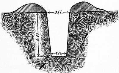
Plate 23.—Type of communication trench.
The location of the communication trench with respect to the fire trench and the arrangements of the approaches is shown in detail in Plate 1.
The profile of the ordinary communication trench is shown in Plate 23.
Dugouts
During the artillery bombardment few men are left in the fire trenches. The remainder of the garrison is held under cover a short distance to the rear. This cover is provided by a system of dugouts connected with the fire trench through underground passageways that lead to the communication trench. This arrangement is shown in Plate 1.
A profile of the latest type of dugout is shown in Plate 24.
The solid earth cover is from 12 to 18 feet thick, which gives protection from all but the very largest caliber shells.
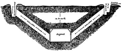
Plate 24.—Type of dugout.
Effective resistance is supplied by roofing materials as follows:
1. From shrapnel bullets: 2-inch planks covered with 12 inches of earth.
2. From 3-inch shells: 4-inch planks supporting 4 feet of earth with a top layer of heavy stones to cause an early shell burst.
3. From howitzers of less than 6 inches caliber: 12-inch beams or logs covered with 8 feet of earth.
4. From the largest caliber guns: 15 to 25 feet of earth.
The following table shows the penetration of the German S bullet at a range of 200 yards:
Inches
Steel plate 3/8
Broken stone 6
Brickwork, cement and mortar 9
Brickwork, lime and mortar 14
Sandbags 24
Sand, loose 30
Hardwood, oak, etc. 38
Earth 50
Soft wood, poplar, etc. 58
Clay 60
Dry turf 80
In addition to the regular "dugouts" for the supports, the latest type trenches have squad dugouts just in rear of the bays of the fire trench. These provide shelter during bombardment for the members of the squad not actually required on duty in the trench bay.
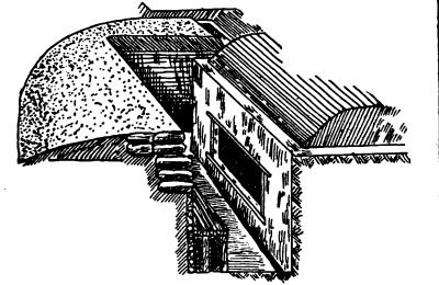
Plate 24a.—Section of traversed type of fire trench showing entrance to squad dugout.
Communications
The fire trench is connected with the cover for supports by a system of zigzag trenches having the profile shown in Plate 23. The arrangement is shown in Plate 1.
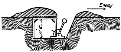
Plate 25.—Profile of trench mortar emplacement.
Trench Mortar Positions
Somewhere between the first line fire trench and the cover for the supports is a line of emplacements for the trench mortars. Plate 25 shows a profile of the emplacement.
The arrangement of the position is shown in Plate 1.
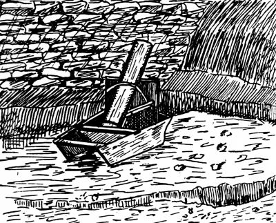
Plate 25a.—Trench mortar.
These trench mortars are used to hurl charges of high explosives varying from 25 to 100 pounds into the enemy's lines. They have a range of from 300 to 1,800 yards.
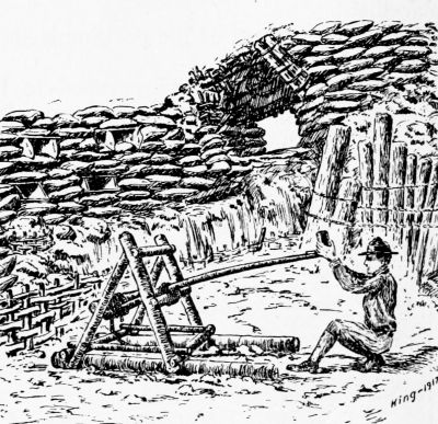
Plate 25b.—Improvised catapult.
Cover for Supports
At a variable distance to the rear of the first line fire trench is located the cover for supports, which is organized much in the same manner as the first line system of trenches and affords a second position in the system to fall back to in case of necessity. These trenches are provided with overhead cover and numerous dugouts for the protection of the men.
Machine Guns
At every available place throughout the defensive position machine guns are located, typical positions of which are shown in Plate 1.
The typical types of cover are shown in Plates 26 and 27.
Machine guns are a very potent factor in trench warfare. They are now being employed to a far greater extent than ever before, and the number is increasing on all the battle fronts as fast as they can be manufactured. The machine-gun positions are carefully concealed from the enemy, and fire is not opened until it is certain that it will be effective.
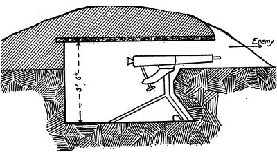
Plate 26.—Profile of type of cover for machine gun.
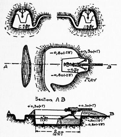
Plate 27.—Type of cover for machine guns.
The selection of the sites for the emplacements should be made with a view to bringing a powerful enfilade or oblique fire on the attacking enemy at effective range, to provide a flanking fire for supporting troops, and to sweep gaps in the line of obstacles.
Their fire should come as a surprise to the attacking party.
In the construction of cover for machine guns the following points should be observed:
1. They must have a platform for the gun and gunner. This may be provided for in the construction of the emplacement or built up with sandbags. The platform should be 3 feet wide and 6½ feet in length.
2. If head cover is provided, it should not differ in appearance from that constructed elsewhere in the trenches. The loopholes must be blinded with gunny sacks.
3. The front of the emplacement should be cut under to receive the leg of the tripod, thus bringing the gun up closer to the parapet and furnishing more cover for the gunner.
4. Splinter-proof shelters should be provided near at hand for the members of the gun detachment.
5. Where the enemy's trenches are near, the position for the emplacement should be selected by day and the actual work done under cover of darkness.
6. The guns should be located so that they support each other by their fire. Alternate positions should be constructed.
7. When located to enfilade straight lines of trenches, special capioniers should be constructed.
Supporting Points
At intervals from 800 to 1,500 yards along the first line, supporting points are established. They may consist of a fortified village or a specially prepared position having a "labyrinth" of trenches and rendered well-nigh impregnable to infantry assault by every defensive device known to modern warfare. They are designed to bring a flanking fire to bear upon the intervening intervals with the idea that troops cannot pass beyond them until they are reduced.
Village Defense
The following was the actual scheme employed for the defense of a French village and exemplifies the thoroughness with which defenses must be organized.
The village was about 700 yards in rear of the front line, and had three keeps surrounded with wire entanglements and independent of each other, but with an elaborate system of communication trenches. Water and four days' rations were stored in each keep, and wells dug. Each of the keeps held about one company. The communication trenches were about 6 feet deep, used as far as possible as fire trenches, and well traversed. Firing platforms were revetted with brushwood, and shelters made all over the village. In addition to keeps, a series of lines existed in the rear of the front line, intercommunicating and provided with barbed wire. A small wood on one point of the front was defended by a network of low wire entanglements and a line of high wire netting.
Every officer had to know all about his section and its communications with right and left. Telephone wires were laid low down in communication trenches and fastened a few inches from ground with wooden pickets.
Machine guns were placed so as to flank salients. A 65-mm. field gun was placed in the front line to sweep the village, and an observation station placed in a tree. The observer wore a green mask and green sheet.
Great use was made of brushwood and undergrowth to revet steps of firing platform.
All work was carried out by regimental officers and men without help from the engineers, who were fully employed in mining. The garrison of the village and the front line trenches in the vicinity was about one battalion, but the fire trenches were sufficient for three battalions.
Chapter V[1]
USE AND IMPROVEMENT OF NATURAL COVER
A screen or mask consists of hedges, crops, underbrush, etc., which hide the rifleman without, however, protecting him from fire.
Cover or shelter consists of walls, earthworks, etc., which protect the rifleman from fire.
On the battlefield, natural features that screen and shelter should be utilized as much as possible, as they possess the following advantages over artificial works:
(a) Their organization demands less work.
(b) Concealment is easier.
(c) From their nature, it is difficult for the enemy to estimate, for a given length, the number of men sheltered.
They possess, however, certain disadvantages:
(a) The protection is sometimes so excellent that, morally as well as materially, it becomes difficult to leave the shelter. Example: quarries with obstructed exits. Therefore, good judgment must be exercised in the selection.
(b) Some of them are too visible. Example: large hedges. In this case their range can be easily found.
As a general rule, do not occupy them uniformly and do not change the appearance of the organized parts.
Organization of the cover:
To organize the cover which protects troops from fire, construct suitable positions for firing and resting. To utilize the screens which merely hide the troops without protecting them from fire, dig trenches behind these screens in the following manner:
(a) Choose the points which give the best field of fire.
(b) Construct cover for firing.
(c) Construct a shelter.
The constructions are usually "individual" in the first period of work; afterwards, they are organized "collectively." The covers are: (1) for riflemen lying down, (2) for riflemen sitting down, and (3) for riflemen standing up.
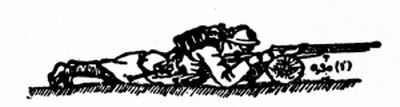
Plate 27a.—Use of the cover without improvement.
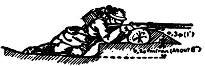
Plate 27b.—First period.
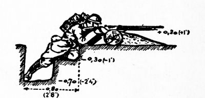
Plate 27c.—Second period. Progressive improvement of the cover.
Individual Organization of Natural Cover
Examples of hasty individual cover behind trees, bushes, or branches:
(a) Fallen tree (logs or branches), the height of which is at a maximum of 1 foot above the ground:
(b) Fallen tree, the top of which is more than 1 foot above the ground.
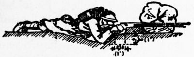
Plate 27d.—First period.
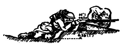
Plate 27e.—Second period
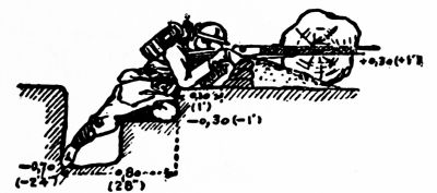
Plate 27f.—Third period.
Wood which does not afford sufficient protection against bullets must be reinforced by earth at the right and against the cover 1 foot behind. Plates 27d, 27e, and 27f show the progressive improvement of the cover.

Plate 27g.—Sharp ridges, furrows, or top of a crest at the end of a gentle slope.
Examples of hasty individual covers behind a furrow, a crest, a heap of sand or earth:
Dig the ground as near as possible to crest A of the furrow in the manner indicated for the cover installed behind a fallen tree more than 1 foot high.

Plate 27h.—Narrow furrows.
Use the earth excavated between furrows A and B to build up the earth between furrows B and C and fill up furrow C; continue afterwards as for the sharp ridge.
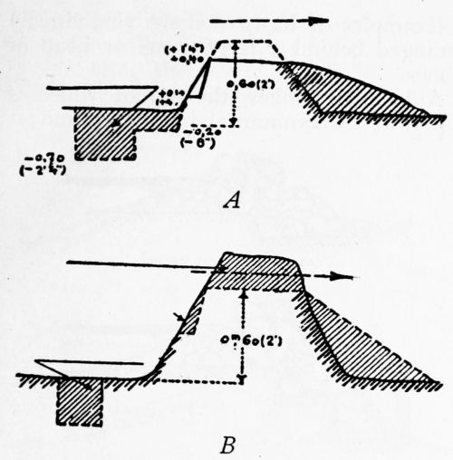
Plate 27i.—Low wall of earth, or earth and sand heaps, more than 2 feet high (two methods, A or B).
(A) Lower the height about 8 inches; throw the earth forward. Dig a trench as indicated in the figure.
(B) Make a loophole in the pile of earth, showing oneself as little as possible. Improve the firing position by making a place for the right leg and an elbow rest.
Examples of hasty shelters (individual) arranged behind a large stone or heap of stones.
A heap of stones, the top of which is 1 foot at a maximum above the ground:
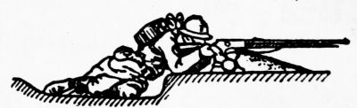
Plate 27j.—First period.
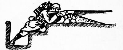
Plate 27k.—Second period.
General Organization of Natural Cover
This consists in connecting up and coordinating the individual work under the direction of the squad commander. The work should be carried out on the lines adopted for the individual work and the rules prescribed for the construction of artificial cover (profiles, depths, various shelters) should be followed as far as possible. In arranging the cover, the squads should utilize the natural features of the terrain.
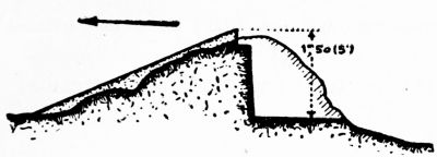
Plate 27l.—Arrangement for a mound of earth.
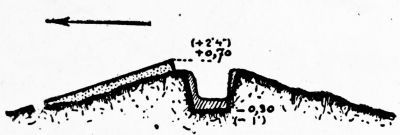
Plate 27m.—Arrangement for a dry ditch.
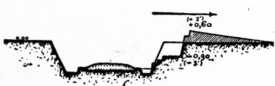
Plate 27n.—Arrangement for a sunken road defended on the side towards the enemy.
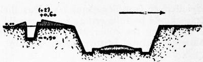
Plate 27o.—Arrangement for a sunken road defended from the rear.
Ditches full of water, drains, streams:
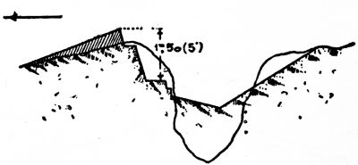
Plate 27p.—Arrangement of a large ditch.
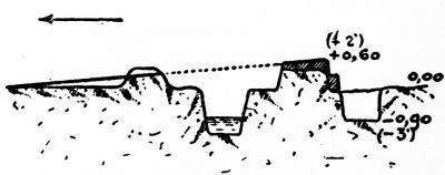
Plate 27q.—Arrangement of a ditch full of water.
Ordinary roads, road and railroad embankments, and sunken roads:
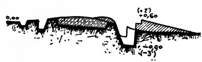
Plate 27r.—Arrangement of an ordinary road defended on the side toward the enemy.
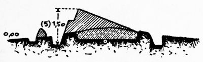
Plate 27s.—Same defended from the rear.
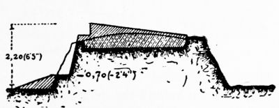
Plate 27t.—Road embankment, defended from the rear.
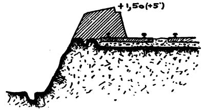
Plate 27u.—Arrangement of a railroad embankment.
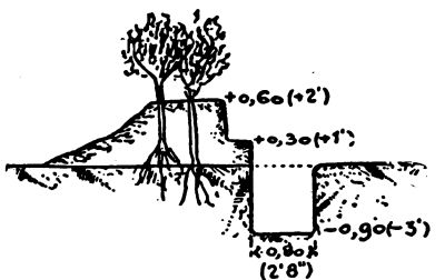
Plate 27v.—Arrangement of a sunken road.
Hedges and woods:
Dig a trench behind the hedge and throw the earth against it; make openings in the hedge to facilitate view and fire . If the hedge is low, deepen the trench, but make the parapet lower than the hedge which masks it.
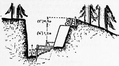
Plate 27w.—Arrangement of a hedge.
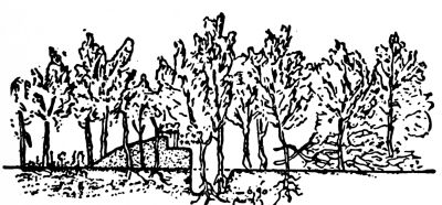
Plate 27x.—Arrangement of the edge of a wood.
Avoid destroying the natural appearance of the wood; do not cut the trees and brush on a certain depth, but cut off branches where necessary to obtain a field of fire. Behind this strip cut the brush and small trees so as to make a path 3 to 4 yards wide. Construct a trench behind the mask of trees. The parapet can be raised up to 2 or even 3 feet. Construct abatis on the parts of the border of the wood, where it will not interfere with the fire.
Walls:
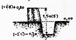
Plate 27y.—Arrangement of a wall 2 feet 8 inches high.
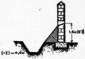
Plate 27z.—Arrangement of a wall 8 feet high.
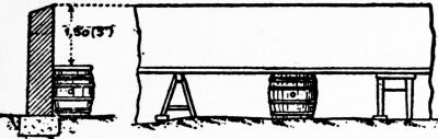
Plate 28.—Arrangement of a wall more than 8 feet high without making loopholes.
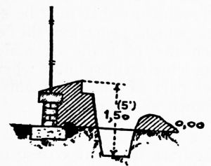
Plate 28a.—Arrangement of an iron fence built on a low wall.
FOOTNOTES:
Chapter VI
REVETMENTS
A revetment is a covering or facing placed upon an earth slope to enable it to stand at an inclination greater than it would naturally assume. Some revetments also increase the tenacity of slopes and diminish the injury by fire. The upper parts of revetments that may be struck by projectiles which penetrate the cover of earth must not be made of materials of large units which will splinter when struck. The upper part of the revetments is technically known as crowning.
Sandbags
Sandbags are made of coarse canvas or burlap. They are 33 inches long and 14 inches wide. They are filled loosely with earth or sand about ½ cubic foot to a bag. Having been placed in position they are pounded down with a shovel to a rectangular form when they will fill a space about 20 by 13 by 5 inches.
The sandbag revetment is constructed by laying alternate rows of headers and stretchers, breaking joints. The tied ends of the headers and seams of the stretchers are put into the parapet. Men working in pairs lay the bags and set them firmly in place with a spade or mallet.
The advantages are:
1. The portability of the empty bags. Only 62 pounds per one hundred bags.
2. They may be filled with any kind of soil.
3. They are rapidly filled and easily placed in position.
4. They are invaluable in making repairs.
5. They will not splinter.
The only disadvantage is that they are not durable. The cloth soon goes to decay and the filling material crumbles away.
Plate 29 shows the appearance of a sandbag revetment as seen from the front and from the end.
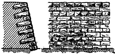
Plate 29.—Sandbag revetment.
A squad of six men with two shovels and one pick should fill 150 bags in an hour. One man uses the pick, two shovel the dirt into the bag, one holds the bag open and two men tie the bags. Having the filled bags ready to hand ten men will lay 75 square feet of revetment in an hour. Four men lay the bags and flatten them out while six carry them.
Brush
Brush is used in many forms for revetting. Almost any kind will serve the purpose. For weaving, it must be live and is most pliable when not in leaf. It should not be more than 1 inch in diameter at the butt. When cut it should be assorted in sizes for the different class of revetments. Poles 2½ inches in diameter are cut for the supports.
Fascines
A fascine is a cylindrical bundle of brushwood tightly bound. The usual length is 18 feet, the diameter 9 inches, and the weight normally about 140 pounds. Lengths of 6 and 9 feet, which are sometimes used, are most conveniently obtained by sawing a standard fascine into two or three pieces.
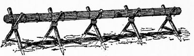
Plate 29a.—Fascine.
Fascines are made in a cradle which consists of five trestles, the outer ones being 16 feet apart. The trestle is made by driving two sticks about 6½ feet long and 3 inches in diameter in the ground and lashed at the intersection as shown in Plate 29a. In making the cradle, plant the two end trestles first. Stretch a line from one to the other over the intersection. Place the others 4 feet apart and lash them so that each intersection comes fairly to the line.
To build a fascine, straight pieces of brush, 1 or 2 inches at the butt, are laid on, the butts projecting at the end 1 foot beyond the trestle. Leaves should be stripped and unruly branches cut off, or partially cut through, so that they will lie close. The larger, straighter brush should be laid on the outside, butts alternating in direction, and smaller stuff in the center. The general object is to so dispose the brush as to make the fascine of uniform size, strength and stiffness from end to end.
When the cradle is nearly filled, the fascine is compressed or choked by the fascine choker (Plate 30), which consists of two bars, 4 feet long, joined 18 inches from the ends by a chain 4 feet long. The chain is marked at 14 inches each way from the middle by inserting a ring or special link. To use, two men standing on opposite sides pass the chain under the brush, place the short ends of the handles on top and pass the bars, short end first, across to each other. They then bear down on the long ends until the marks on the chain come together. Chokers may be improvised from sticks and rope or wire.
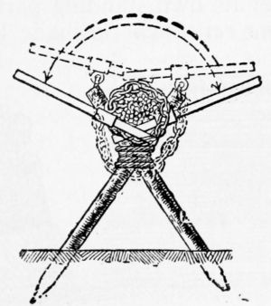
Plate 30.—Method of using the fascine choker.
Binding will be done with a double turn of wire or tarred rope. It should be done in twelve places 18 inches apart, the end binders 3 inches outside the end trestles. To bind a fascine will require 66 feet of wire.
Improvised binders may be made from rods of live brush; hickory or hazel is the best. Place the butt under the foot and twist the rod to partially separate the fibers and make it flexible. A rod so prepared is called a withe. To use a withe, make a half-turn and twist at the smaller end. Pass the withe around the brush and the large end through the eye. Draw taut and double the large end back, taking two half-hitches over its own standing part.
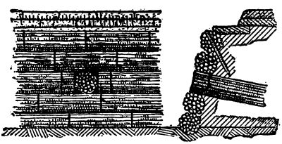
Plate 31.—Fascine revetment.
A fascine revetment is made by placing the fascines as shown in Plate 31. The use of headers and anchors is absolutely necessary in loose soils only, but they greatly strengthen the revetment in any case. A fascine revetment must always be crowned with sod or bags.
In all brush weaving the following terms have been adopted and are convenient to use:
Randing.—Weaving a single rod in and out between pickets.
Slewing.—Weaving two or more rods together in the same way.
Pairing.—Carrying two rods together, crossing each other in and out at each picket.
Wattling.—A general term applied to the woven part of brush construction.
A hurdle is a basket work made of brushwood. If made in pieces the usual size is 2 feet 9 inches by 6 feet, though the width may be varied so that it will cover the desired height of slope.
A hurdle is made by describing on the ground an arc of a circle of 8-foot radius and on the arc driving ten pickets, 8 inches apart, covering 6 feet out to out. Brush is then woven in and out and well compacted. The concave side of a hurdle should be placed next the earth. It warps less than if made flat.
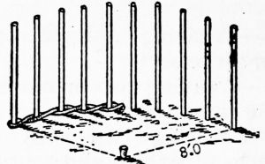
Plate 32.—Method of laying out hurdle.
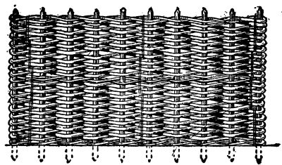
Plate 33.—Hurdle.
In weaving the hurdle, begin randing at the middle space at the bottom. Reaching the end, twist the rod as described for a withe but at one point only, bend it around the end picket and work back. Start a second rod before the first one is quite out, slewing the two for a short distance. Hammer the wattling down snug on the pickets with a block of wood and continue until the top is reached. It improves the hurdle to finish the edges with two selected rods paired. A pairing may be introduced in the middle, if desired, to give the hurdle extra endurance if it is to be used as a pavement or floor. If the hurdle is not to be used at once, or if it is to be transported, it must be sewed. The sewing is done with wire, twine or withes at each end and in the middle, with stitches about 6 inches long, as shown in Plate 33. About 40 feet of wire is required to sew one hurdle. No. 14 is about the right size, and a coil of 100 pounds will sew forty hurdles. Three men should make a hurdle in two hours, two wattling and the third preparing the rods.
Continuous Hurdle.—If conditions permit the revetment to be built in place, the hurdle is made continuous for considerable lengths. The pickets may be larger; they are driven further apart, 12 or 18 inches, and the brush may be heavier. The construction is more rapid. The pickets are driven with a little more slant than is intended and must be anchored to the parapet. A line of poles, with wire attached at intervals of two or three pickets, will answer. The wires should be made fast to the pickets after the wattling is done. They will interfere with the weaving if fastened sooner. Two men should make 4 yards of continuous hurdling of ordinary height in one hour.
Brush Revetment.—Pickets may be set as above described and the brush laid inside them without weaving, being held in place by bringing the earth up with it. In this case the anchors must be fastened before the brush laying begins. The wires are not much in the way in this operation.
Gabion Making.—A gabion is a cylindrical basket with open ends, made of brush woven on pickets or stakes as described for hurdles. The usual size is 2 feet outside diameter and 2 feet 9 inches height of wattling. On account of the sharp curvature somewhat better brush is required for gabions than will do for hurdles. The gabion form is made of wood, 21 inches diameter, with equidistant notches around the circumference, equal in number to the number of pickets to be used, usually eight to fourteen; less if the brush is large and stiff, more if small and pliable. The notches should be of such depth that the pickets will project 1 inch outside the circle. The pickets should be 1½ to 2 inches in diameter, 3 feet 6 inches long, sharpened, half at the small and half at the large end.
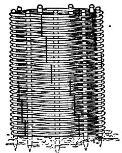
Plate 34.—Gabion.
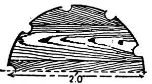
Plate 35.
To Make a Gabion.—The form is placed on the ground. The pickets are driven vertically in the ground, large and small ends down, alternately. The form is then raised a foot and held by placing a lashing around outside the pickets, tightened with a rack stick. (See Plate 36.)
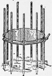
Plate 36.—Forming the gabion supports.
The wattling is randed or slewed from the form up. The form is then dropped down, the gabion inverted, and the wattling completed. If the brush is small, uniform, and pliable, pairing will make a better wattling than randing. If not for immediate use, the gabion must be sewed as described for hurdles, the same quantity of wire being required.
The gabion, when wattled and sewed, is completed by cutting off the tops of the pickets, 1 inch from the web, the bottom 3 inches. The latter are sharpened after cutting and driving a pairing picket through the middle of its length and a little to one side of the axis. Three men should make a gabion in an hour.
Gabions may be made without the forms, but the work is slower and not so good. The circle is struck on the ground and the pickets driven at the proper points. The weaving is done from the ground up. The entire time of one man is required to keep the pickets in their proper positions.
If brush is scarce, gabions may be made with 6 inches of wattling at each end, the middle being left open. In filling, the open parts may be lined with straw, grass, brush, or grain sacks to keep the earth from running out.
Gabion Revetment.—The use of gabions in revetment is illustrated in Plate 37. If more than two tiers are used, the separating fascines should be anchored back. Gabion revetment should be crowned with sod or sandbag.
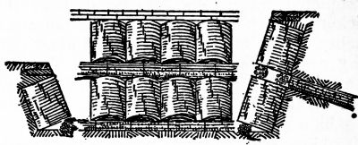
Plate 37.—Methods of use of gabion.
The advantages of gabion revetment are very great. It can be put in place without extra labor, faster and with less exposure than any other. It is self-supporting and gives cover from view and partial cover from fire quicker than any other form. Several forms of gabions made of material other than brush have been used. Some of them are sheet iron, empty barrels and hoops. The disadvantages of iron are that it splinters badly, is heavy, and has not given satisfaction. If any special materials are supplied, the methods of using them will, in view of the foregoing explanation, be obvious.
Timber or Pole Revetment.—Poles too large for use in any other way may be cut to length and stood on end to form a revetment. The lower end should be in a small trench and have a waling piece in front of them. There must also be a waling piece or cap at or near the top, anchored back. Plate 38 shows this form.
Miscellaneous Revetments.—Any receptacles for earth which will make a staple, compact pile, such as boxes, baskets, cans, etc., may be used for a revetment. Canvas or burlap stretched behind pickets is being used to a great extent on the battle fronts of Europe. If the soil will make adobe, an excellent revetment may be made of them, but it will not stand wet weather.
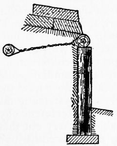
Plate 38.—Timber revetment.
Chapter VII
WORKING PARTIES
The infantryman will always be called upon to construct the trench which he is to occupy. Each company is provided with portable tools, which the men carry, and each infantry regiment is provided with tools for the purpose. The digging tools consist of picks and shovels.
When it has been decided to locate fire trenches along a certain line officers will lay out the cutting lines and mark them with tape or otherwise. A company will be assigned for the construction of a definite section of the trench.
Let us work out the procedure, assuming that the work may go on unmolested by the enemy. Such, however, is not usually the case. The enemy will do anything in his power to prevent construction work. If, however, we are familiar with the details of the work and know how to go about it in an orderly and systematic manner under conditions of noninterference by the enemy, we will be able to carry out these details of organization and procedure under more or less trying conditions when the time comes.
Officers have established the trace of the trench and marked the cutting lines. It is the ordinary traversed type, 18 feet bays with traverses 5 feet wide and 5 feet deep, as shown in Plate 14.
The company is composed of, say, twelve squads organized into three platoons of four squads each. Six bays of the trench have been assigned to the organization for construction. This gives a task to each platoon of two bays, including one complete traverse and a half traverse on each flank.
Tools have been issued to the first and third squads of each platoon, the front rank men carrying picks and the rear rank men shovels.
The company is marched in column of squads to the site of the trench, approaching it from the rear, and halted with the head of the column fifteen paces in rear of and opposite the right of the section assigned; that is, in rear of the first bay of the section. The second platoon is then conducted by the platoon commander and halted with its head opposite the third bay. The third platoon is in like manner conducted to the rear of the fifth bay. Each platoon commander then has the two rear squads of his platoon, conducted to a point behind the bay on his left, i.e., the second, fourth and sixth respectively. This allows two squads for the work in each bay, the leading squad furnishing the first relief and the rear squad the second.
The leading squad of each column is then marched to a point two paces in rear of the rear cutting line of the trench, where they take off their packs and lay their rifles on them. The corporal and his rear rank man fall out. The corporal assigns tasks, number ones to the first 2-yard section, number twos to the second and number threes the third.
The tasks are shown in Plate 39. The corporal superintends the work. Number 4 rear rank marks out the cutting lines with his shovel around the traverses and starts work on them.
Experience has shown that the best method of dividing up the work is to group the men in pairs, one man with a pick and one with a shovel and to prescribe that they relieve each other.
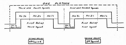
PLATE 39. ORGANIZATION OF A WORKING PARTY
The leading squads assigned to each bay work at top speed for 30 minutes. At the end of the twenty-eighth minute the corporal of the rear squad brings his men up and deploys them. At a signal from the platoon commander the men of the first and third squads drop their tools, get out of the trench, and proceed to the rear, where they rest. The men of the second and fourth squads jump into the trench and take up the task. At the end of another 30 minutes this procedure is again carried out.
This scheme of assigning tasks and procedure was given an exhaustive test in 1915 in the course of testing out various types of intrenching tools. It worked to perfection.
The bays are first completed, after which the traverses begun by No. 4 rear rank are finished up. Great care should be taken to make the dimensions of the trench as accurate as possible. The squad leader is held responsible for this. He should provide himself with two sticks. On one the following lengths are laid off: 1 foot, width of berms, and height of parapet; 1 foot 4 inches, width of firing banquet, height of firing banquet above bottom of trench, and width of bottom of trench. The other stick has the following lengths measured on it: 4 feet, depth of trench from ground surface to the top of firing banquet; 5 feet 4 inches, depth of trench from ground surface to bottom of trench. (See Plate 15 for dimensions of standing trench.)
When the circumstances are such that the work of trench construction is interfered with by the enemy, a modification of the system outlined here will have to be made, but the details should be adhered to as closely as possible.
When night work is necessary the trace should be staked out before complete darkness sets in. If the trace can only be made after dark, visible reference points needed with white paper, white tape or screened flashlights may be utilized. Stick to the details of the deployment, the laying out of tasks and the procedure as indicated for day work as closely as possible. Avoid making any more noise than is absolutely necessary; allow no smoking and require such conversation as is necessary to be made in whispers. Protect the workers by a system of patrols to the front.
Non-commissioned officers are held responsible for a systematic and orderly execution of the work being performed by their units. The captain cannot be everywhere along the line. He has to depend upon the platoon and squad leaders in the work. That is why you should study it and know about it so as to be able to make good when the time comes.
Chapter VIII
GRENADE WARFARE
The use of hand grenades as an implement of warfare dates back many centuries. History records their use as far back as 1536. Up to the close of the eighteenth century soldiers were trained in the throwing of hand grenades, and for this reason were called "grenadiers." At first there were a few in each regiment, later entire companies were formed, and finally each infantry unit that corresponds to our battalion of today had its own grenadier unit.
Then there was a period of time when more open formations were adopted, when there was less opportunity for the employment of grenades and their use was practically eliminated from the battlefield and confined to sieges, where they have been used more or less since the dawn of military history.
With the advent of the Russo-Japanese War came the extensive use of trenches on the battlefield, and with the trenches came the hand grenades which were used in large quantities by both sides. This was especially the case when the fighting lines came to close quarters and in the assaults against the forts at Port Arthur.
When the European war resolved itself into trench warfare, such as it is today, the use of hand-thrown projectiles assumed an importance heretofore never attained, and today we find ourselves employing hand grenades in every phase of the conflict.
Employment of Grenadiers
Grenadiers are employed on both the offensive and defensive. They accompany the attacking lines in the advance on the enemy's position, they clear the fire trenches and communication trenches after parts of the enemy's lines have been taken, and on the defense they assist the riflemen in repelling attack and engage the enemy whenever he has obtained a lodgment in the trenches.
Organization
While every infantryman receives a certain amount of instruction in grenade throwing, there should be a grenadier squad in each platoon specially instructed and trained in this most effective auxiliary method of trench warfare. Not all men possess the temperament and qualifications necessary to make efficient grenadiers. Hence the personnel of the grenadier squad should be carefully selected. Strong physique, personal courage and steadiness in emergencies are the qualifications that count. Men fond of outdoor sports, other things being equal, will be found the best.
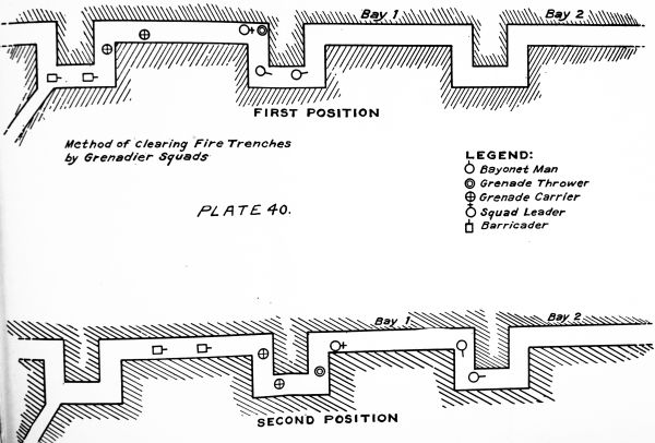
PLATE 40.
The grenadier squad is organized as follows:
Front Rank.
No. 1. First bayonet man. No. 2. Second bayonet man. No. 3. Grenade thrower. No. 4. Squad leader, observer and director.
Rear Rank.
No. 1. First carrier. No. 2. Second carrier. No. 3. Barricader. No. 4. Barricader.
Duties
The duties of the several members of the squad vary under different circumstances of their tactical employment which will be fully explained below. In general they are as follows:
Bayonet Men.—The bayonet men move in advance of the grenade throwers. When the grenade thrower has thrown his grenades into the objective trench the bayonet men must be ready to take instant advantage of the temporary demoralization of the enemy caused by the explosions and clear the way for a repetition of the operation.
Grenade Thrower.—The grenade thrower must be ready and able to throw a grenade at once whenever the bayonet men or squad leader may direct.
Squad Leader.—The squad leader directs the operations of the squad. He goes wherever his presence is necessary. He keeps a close watch to the flanks. He replaces casualties and attends to the forwarding of grenades to the thrower. He acts as a grenade thrower whenever he can assist the operations in that capacity.
Carriers.—The carriers carry as many grenades as possible, and when their supply is exhausted they go to the reserve depots and replenish. They are responsible for a continuous supply of grenades to the throwers.
Barricaders.—The barricaders are charged with the construction of barricades. They carry sandbags and tools for filling them. In addition they carry as many grenades as possible. They hold themselves in readiness to go forward and construct a barricade or cover at any point designated by the squad leader.
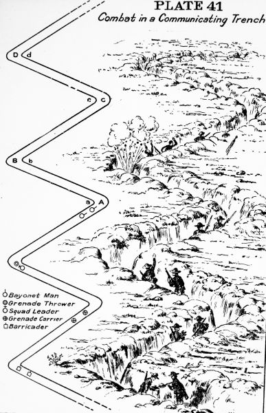
PLATE 41 Combat in a Communicating Trench
General.—All the men of the squad must be trained and prepared to take over the duties of any other member. Before undertaking any operation each man of the squad should thoroughly understand the part he is to play in it.
Formation.—The formation for the several classes of tactical employment will be explained when each is considered below.
Offensive Operations
When it has been decided to attack a certain sector of the enemy's position a detailed reconnaissance is made with a view to locating and developing every element of the position, detailed plans are made and imparted to all concerned. (See Chapter XI.)
The phases of the attack consist of: (1) The artillery preparation; (2) the infantry assault; (3) the occupation and organization of the captured position, and preparation to meet a counter attack.
During the course of the artillery preparation grenadier squads work their way across "no man's land" and establish themselves sufficiently close to throw grenades into the fire trenches. Failing in this they accompany the assaulting troops.
When they are able to work up close they cover the advance of the infantry assaulting lines by showering grenades into the enemy's fire trenches after the curtain of artillery fire has been extended back into his position to prevent the supports and reserves from coming up to the front.
All men of the squad carry as many grenades as possible and such number as the squad leader may designate act as throwers, while the others act as carriers and prepare the grenades for throwing. Accurate throwing, properly observed and distributed, will greatly assist in preparing for a successful assault.
Clearing Fire Trenches
No matter how well the infantry assault on the enemy's fire trenches may be conducted, it rarely succeeds in occupying the hostile position throughout its entire length. Casualties, loss of direction, and unexpected obstacles encountered are bound to break up the assaulting line more or less, thereby leaving gaps in the captured position. Furthermore the attack on a line of trenches takes place on a relatively small front by a large number of men. When the trenches are finally reached and a lodgment effected there will be great overcrowding. Provision must be made immediately for extending the line, otherwise the casualties at these points will be exceedingly heavy.
It is the particular duty of the grenadier squads to clear these "gaps" of the enemy as quickly as possible. For this purpose an efficient and well-organized storming party must be immediately available.
Let us say that, after careful artillery preparation, the assault has reached the enemy's fire trench. There is much overcrowding at the points where lodgments have been effected. There is a gap in the line between two adjacent elements. How is this cleared of the enemy?
The grenadier squad immediately forms for action. Two bayonet men are in the lead, followed by the grenade thrower, who is in turn followed by the two carriers. Further to the rear are the two barricaders, who carry a reserve supply of grenades in addition to their sandbags and shovels. The squad leader is where he can best direct the operations.
The grenadier squad is formed as shown in the first position, Plate 40.
1. The grenade thrower puts grenades: (1) into bay 1, at A; (2) into bay 2, at D; (3) into bay 1, at B; (4) into the traverse leg at C.
2. When the four grenades have exploded the bayonet men rush into bay 1, the leader advancing into the first leg of the traverse trench below B, while his mate remains in the bay for a moment.
3. The squad leader rushes around the traverse to A, followed by the grenade thrower.
4. When the bay and the next traverse passages are all cleared of the enemy the word "O.K." is passed back to the squad leader by the bayonet men. The bayonet men get into their proper positions and the remainder of the squad rush into the cleared bay 1 and prepare for the further clearing of succeeding bays in the same manner as described above.
Take the diagram on Plate 40. Study it out in connection with the text and you will see how this system works out.
The men work in pairs, the two bayonet men together; the two carriers behind the thrower; the two barricaders sufficiently far to the rear to be protected by a corner of solid earth. The squad leader must of necessity go where his presence is necessary. Usually he stays as near the grenade thrower as possible.
When the enemy's grenadier parties are also very active in the sector, the distances between pairs are extended so that no more than two men are exposed in any one bay or traverse leg.
The formation of the squad must be preserved as long as possible. You will appreciate that when losses occur the squad leader will have to replace men and the formation will have to be modified to meet the changed conditions. This makes it absolutely necessary that every member of the squad be competent to take over the duties of any other member.
When the squad has reached the limit of its advance the barricaders will come forward and construct a barricade in such position that it is well in view from a corner some distance behind.
No passing of bombs forward from man to man is permitted. When the first carrier's supply is exhausted he returns to the rear to secure a fresh supply from the reserve grenade carriers who are following the grenade squad, and who have by now advanced to a point where their supply is available. As soon as his supply is replenished he returns to his proper position in the formation. Should the second carrier run out of grenades the squad leader may cause one of the barricaders to take all the grenades in the possession of the two and replace him while he goes to the rear to secure a fresh supply.
In the meantime other grenadier squads are clearing out the communication and supervision trenches, blocking up the exits to dugouts and destroying machine-gun detachments that have thus far escaped. The assaulting troops have passed on towards the second line, covered by the curtain of fire of the artillery.
Clearing Communication Trenches
The clearing of communication trenches is effected much in the same manner as explained for the fire trench. The grenadier squad is organized and formed in the same manner. The squad works its way into the communication trench by bombing each leg until they arrive at a point where the formation, as illustrated in Plate 41, can be assumed. The grenade thrower throws grenades into the trench at B and then at C. As soon as these have exploded the bayonet men take advantage of the confusion to advance into the leg A-B under cover of the shoulder b, the squad leader and thrower advance to A, the carriers to the point formerly occupied by the squad leader, and the barricaders to the point formerly occupied by the carriers. The thrower then puts grenades into the trench at C and then at D, after which the whole squad advances another notch as formerly explained.
Where island traverses are encountered the thrower puts a grenade on each side of the traverse and one in the rear of it. The bayonet men, one on a side, assault around the traverse and meet on the far side, and the operation proceeds as heretofore explained.
Night Operations
The grenadier squads may be called upon at night, to perform any of the services that are theirs by day, and in addition may be called upon to make night reconnaissances. For this work the men must be able to organize and reorganize the squad quickly and noiselessly. The throwers must be particularly efficient. There must be the highest order of team work.
Grenadier Patrols
Grenadier patrols are sent out at night to make reconnaissances of the enemy's lines with a view to getting information which may include:
1. Location and organization of line.
2. The length of line occupied.
3. Numbers and disposition of occupying troops.
4. To get an accurate description of the ground.
5. To locate observation and listening posts or any other advanced positions.
6. To locate machine guns.
These patrols may consist of from two men to the entire grenadier squad. In a patrol of six or eight men two of them carry rifles and belts, bayonets fixed. The remaining members of the patrol carry no equipment except a haversack filled with grenades. The grenades are used only in case of emergency. It is a reconnoitering patrol charged with gaining information and therefore does not enter into an encounter with the enemy except as a last resort.
The men move or crawl without noise and take advantage of all cover that the ground affords. If they suspect they are observed, they should "freeze" to the ground and remain absolutely motionless. On dark nights it is easy to lose the direction and for the men to lose one another. Every device or scheme to lessen risks in this respect must be employed. The men may tie themselves lightly together so they will not proceed in a bunch and at the same time retain connection with each other.
Notes on Grenade Warfare
The first step in the training of a grenadier is to overcome his fear of the grenade itself. This is accomplished by first having him practice fuse lighting with dummy grenades having live fuses. The men will be impressed with the fact that the grenades are dangerous weapons and that familiarity in handling them must not be permitted to degenerate into carelessness.
The next step towards efficiency is the development of accuracy of throwing. For short distances it may be lobbed from the shoulder by a motion similar to "putting the shot." Stick grenades may be thrown for a short distance like throwing a dart. In the trenches the grenade should be thrown with an overhand motion like the bowler of a cricket ball, as there is danger of exploding them by knocking the hand against the back of the trench.
The men should be taught to throw from all positions—standing, sitting, kneeling and prone.
Should the grenade with a time fuse be dropped in the act of throwing, there is time to pick it up and throw it out of the trench before it explodes. Under no circumstances must it be allowed to explode in the trench.
Communication throughout the squad in action should be maintained at all times. System is required to insure the throwers having a supply of grenades on hand all the time and that casualties are promptly replaced.
Quick action is essential to success. Crawling and stalking give the enemy what he is waiting for.
Arrangements to assist a storming party by rifle and machine-gun fire are of the utmost value and should be provided whenever possible. Care must be taken to provide a signal which will mark the progress of the storming party through the trenches. A helmet held up on a bayonet will do this.
All grenadiers must be especially trained in the filling of sandbags and making sandbag barricades.
The work of the observer is difficult and requires much practice. He must give his directions to the thrower in no uncertain terms. When the thrower has missed his objective the observer will give positive directions for the next throw. Instead of saying "A yard too much to the left," he will say, "Throw a yard to the right." Positive directions, even if only half heard, are of some use; negative directions are certain to be both confused and confusing. The observer should be expert in the use of the periscope.
Hand Grenades and Petards
The hand grenade used by our allies on the western front is the bracelet grenade with automatic firing mechanism and consists of a ball of cast iron filled with an explosive and of a leather bracelet which is fastened to the wrist. To the bracelet is attached a piece of rope about 30 centimeters long, having an iron hook at its end.
Just before the grenade is thrown, the hook is engaged in the ring of the roughened wire of the friction primer placed inside the fuse plug which closes the cast iron ball. When the grenade is thrown, the ring with the primer wire, held back by the hook of the bracelet, is wrenched off by a sudden movement of withdrawal from the wrist and the fuse is fired. The explosion takes place four or five seconds later.
This grenade is supplied to the fighting zone ready for use. It is quite complicated. It can be thrown about 25 meters.
The German grenade is composite; it can be thrown by hand or fired from a rifle. As a hand missile, it is used at short distances, 15 to 20 meters. It is composed of a copper rod to the extremity of which is fixed a cast iron cylinder, grooved to facilitate its breaking into small pieces at the moment of explosion. The explosive is placed inside this cylinder. A copper tube, also containing some explosive, is placed in the interior. It is surmounted by a complicated system for closing the grenade and for automatic ignition by percussion, which results in at least 50 per cent. of misfires.
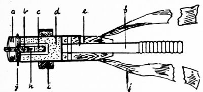
Plate 41b.—British hand grenade No. 1.
a. Removable cap. b. Detonator holder. c. Detonator. d. Explosive charge. e. Wood block. f. Handle. g. Safety pin. h. Firing pin. i. Cast iron ring. j. Streamer.
Used with the rifle, this grenade has a maximum range of 400 meters. At the extremity opposite the grenade, the copper rod ends in a copper stem about 3 centimeters in length, movable about the axis of the rod. This stem is covered with a copper sleeve of slight thickness, which is attached to it only at the extremity fastened to the rod. The diameter of the exterior of the sleeve must be such that it can be pushed into the gun barrel without pressure. To fire the grenade, a blank cartridge is placed in the chamber of the rifle; the quantity of powder left in the cartridge is regulated according to the distance at which the missile is to be thrown. At the moment of firing, the explosive gases penetrate between the sleeve and the stem and jam the sleeve against the grooves of the barrel. The sleeve and the stem, which is attached to it, take a movement of rotation in the grooves of the barrel, which insures the direction of the missile and the maximum efficiency of the explosive gases of the cartridge.
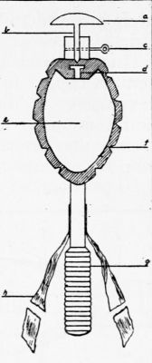
Plate 41c.—The latest type British hand grenade.
a. Percussion cap. b. Firing pin. c. Safety pin. When in place prevents firing pin from striking primer. It is removed just before throwing the grenade. d. Primer. e. Chamber filled with high explosive. f. Cast iron shell, serrated. g. Wooden handle. h. Streamers, to keep the grenade head-on.
The bracelet grenade and the German grenade just described have to be made in a factory. Attempts have been made to construct similar missiles with the explosives which are at hand at the front, cheddite and melinite. Several kinds have been made: a primed cartridge and a primed hand petard, fitted on a wooden paddle, a preserved meat tin can filled with explosive, etc.
The Germans have hand petards similar to those of the Allies but with different explosives. These missiles are primed by a detonator and a slow match and can be thrown about 30 meters. The discharge takes place either automatically or by tinder. They are made on the spot and very rapidly. The assaulting troops carry them in baskets or strung on a circle of wire carried on the shoulder.
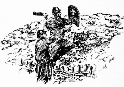
Plate 41d.—Throwing hand grenades.
Grenades and petards constitute a terrible weapon. The projectiles exert considerable moral effect owing to the violence of their explosion and the awful wounds they occasion, and they make it possible to reach the enemy at points where it is impossible to use the rifle and bayonet.
Chapter IX
GAS WARFARE
Germany first made use of poisonous and asphyxiating gases on the field of battle. It has become an accepted element in the present war. Every soldier should, therefore, have a knowledge of the various ways in which gas is employed in the attack, as well as the measures to be taken to counteract its effect in the defense.
The two methods of disseminating the gas over the battlefield are by emanation and grenades charged with it.
Emanation
This method has for its object to create a poisonous or irritant atmosphere. This is accomplished by means of the arsenic and phosphorous gas being forced through tubes in the direction of the enemy or by means of liquefied chlorine, bromide, phosgene and sulphuretted hydrogen gas stored in cylinders under high pressure. To be successful the gas attack must be attended by the following conditions:
1. The weather must be comparatively calm with a wind blowing in the direction of the enemy at about 5 miles an hour. If the wind is too strong the gas will be carried over the enemy's trenches so rapidly that it will not settle in them. If the wind be too light the gas will be carried up into the air and disseminate or may even be blown back into our own trenches, in which case chloride of lime scattered about freely will disperse them.
2. There must be no rain, for that would quickly disseminate the gas and negative the effect.
3. The attack must come as a surprise. If the elements of surprise are missing and the enemy has time to take protective measures, the effect is lost. If the surprise is complete, the enemy trenches should be emptied very quickly.
4. The gas used must be heavier than the air, so that it will sift into the enemy's trenches as it passes them. It is impracticable to decide upon any definite hour for launching the gas attack. Everything depends upon the direction and velocity of the wind. If an hour has been tentatively designated and the wind changes, the attack will have to be postponed.
When an assault follows the gas attack the men should wear the smoke helmets for at least 30 minutes after the dissemination has ceased; in fact they must not be removed until the order to do so is given by the officer commanding the attack. You will appreciate that the enemy's machine gunners may have better protection than the men in the bays of the trenches.
Shell and Grenade Method
In this method the gas dissemination is effected by means of shells or bombs being fired into the enemy's trenches containing the desired substances which are released and give off irritant fumes on explosion. The grenades used weigh about 1 pound. They are similar in appearance to the ordinary tin can grenade. Their effect in a trench will continue for 20 to 30 minutes. In the attack a large number should be concentrated in a particular area to produce a large volume of gas. They are thrown by hand, trench mortar or catapult.
Defense
Surprise must be guarded against in every possible way. The direction of the wind must be continually watched, and when its velocity and direction are specially favorable the protective measures must be kept ready for instant use and special observers posted. Previous to an attack the enemy may remain comparatively quiet for several days. Noises like the moving of sheet iron may be heard. Preparations may be observed along the position. When the attack starts a hissing noise is heard; this latter is one of the indications that may be evident at night.
Helmets
Each man on duty in the trenches is provided with two smoke helmets, specially devised and constructed so as to absorb the gas and neutralize its effect, and which if properly cared for and used will provide complete protection from any substance likely to be used by the enemy. They are fitted with a valve tube through which to breathe and with goggles to see through. There are certain rules prescribed for their care and use.
1. They must not be removed from the protective covering except for actual use against an attack.
2. When the helmet has been used once it should be replaced by a new one.
Dummy Helmets
Dummy gas helmets will be provided in each organization by which the men may be practiced in putting them on. The men must be thoroughly drilled in the methods to be employed.
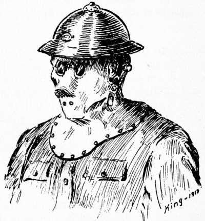
Plate 40a.—Gas helmet.
The following directions accompany the helmets issued to the British Army. When our helmets are issued it is probable that each will be accompanied by a complete set of rules for its use and full instructions for the method of getting into it and for its care and preservation.
Direction for Use and Care of Tube Helmets
Description
These helmets are the same as the smoke helmet already issued, except that stronger chemicals are added and a tube valve provided through which to breathe out. The tube valve makes the helmet cooler and saves chemicals from being affected by the breath. The wearer cannot breathe in through the tube valve; this is intended for breathing out only.
Directions for Use
Remove paper cap from mouthpiece of tube valve. Remove service cap. Pull helmet over head. Adjust so that goggles are over eyes. Tuck in skirt of helmet under coat collar and button coat so as to close in skirt of helmet. Hold the tube lightly in lips or teeth like stem of pipe, so as to be able to breathe in past it and out through it.
Breathe in through mouth and nose, using the air inside the helmet. Breathe out through tube only.
Directions for Care of Tube Helmet
1. Do not remove the helmet from its waterproof case except to use for protection against gas.
2. Never use your tube helmet for practice or drill. Special helmets are kept in each company for instruction only.
Should the goggles become misty during use they can be cleared by rubbing them gently against the forehead.
When lacrimatory gases are used goggles affording mechanical protection may be worn, as these gases are not likely to irritate the lungs, though they sometimes produce sickness.
Improvised Methods
If a soldier does not possess one of the official pattern respirators, the following measures will be found useful:
1. Wet and wring out any woolen article, such as a stocking or muffler, so as to form a thick pad large enough to cover the nose and mouth, and press firmly over both.
2. Place in a scarf, stocking or handkerchief, a pad of about three handfuls of earth, preferably damp, and tie it firmly over the mouth and nose.
3. A wet cloth pulled down over the eyes will be found useful as additional protection, especially against certain gases other than chlorine or when the gas is too strong for the ordinary respirator.
4. A stocking, wetted with water and soda solution or tea, folded into eight folds and firmly held or tied over the nose.
5. A sock folded fourfold similarly wetted and held or tied. If the sock or comforter has been soaked in soda solution it will still act efficiently when dry, though if possible, it should be moist. The spare tapes from puttees may be used for tying on the sock.
6. Any loose fabric, such as a sock, sandbag, woolen scarf or comforter, soaked in urine, then wrung out to allow of free breathing and tied tightly over the nose and mouth.
In the absence of any other cloths, the flannel waistbands issued for winter use could be used for this purpose.
Knapsack Sprayers
Knapsack sprayers are issued for use to clear gases out of the trenches after the cloud has blown over. A man with the sprayer on his back (and wearing his smoke helmet) slowly traverses the trench, working the spray. If this is not done the heavy poisonous gas may linger in the trench for days and be a source of great danger.
If supports or reinforcements enter a trench charged with gas, they should be preceded by a man using a sprayer.
Sprayers are charged with sodium thiosulphate—more commonly known as "hypo"—6 pounds being dissolved in a bucket of water and a handful of ordinary washing soda added.
Garden syringes and buckets may be used if sprayers are not available, but these are not so effective. Sprayers should be charged before they are taken up to the trenches, and should be kept ready for immediate use.
Every officer defending a trench against an enemy gas attack should endeavor to collect information whenever possible, to be sent to headquarters through the usual channels. Particularly valuable is the capture of apparatus used by the enemy either for disseminating gas or for protection against it. If a shell attack is made, unexploded shells or portions of them should be sent through to headquarters at once. The time of day, duration of attack, color, taste or smell of gas used, effect on the eyes, breathing, and all other symptoms should be noted. New gases may be used at any time, and speedy information greatly forwards the adoption of preventive measures.
Chapter X
SERVICE IN THE TRENCHES
Preparations for Entering Trenches
Preparing to enter upon a period of service in the trenches the company commander makes a complete inspection of the company which includes:
1. Inspection of rifles and ammunition.
2. Inspection of equipment, contents of packs, intrenching tools, field glasses, wire cutters, first-aid packets, emergency rations, gas helmets, identification tags, canteens, clothing, etc.
3. Canteens to be filled with water.
4. Test bayonets, fix and unfix.
5. Have company fill magazines.
Inspection of Section
The company commander precedes the company into the trenches and makes a tour and inspection of the section assigned, which includes:
1. Layout of the trenches: fire trench, supervision trench, communication trenches, machine-gun positions, snipers' positions, listening and observation trenches, dugouts, latrines, etc.
2. Locate telephones, reserve ammunition and munitions depots, water supply, gas alarms, tools and any trench accessories and utilities that may be included in the section.
3. Get any information of the enemy that may be of value from the outgoing company commander.
Tactical Disposition
The company commander will then make his tactical dispositions. In occupying the trenches a certain section of the line is assigned to each company. This section contains so many bays of the trench. The following dispositions are suggested as meeting the requirements under our organization:
1. The company is organized into four platoons of four squads each.
2. The section of the line assigned to the company contains eight bays.
3. Support No. 1 consists of the first and second platoons.
4. Support No. 2 consists of the third and fourth platoons.
5. From Support No. 1: Two squads of the first platoon occupy bays 1 and 2; two squads of the second platoon occupy bays 3 and 4.
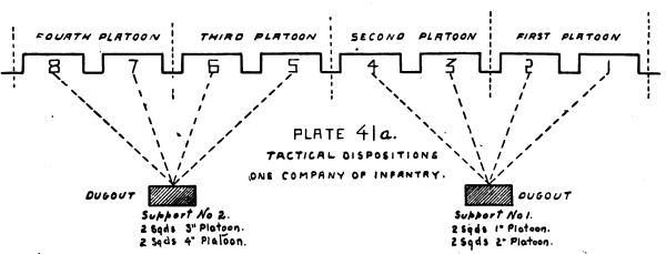
PLATE 41a. TACTICAL DISPOSITIONS ONE COMPANY OF INFANTRY.
6. From Support No. 2: Two squads of the third platoon occupy bays 5 and 6; two squads of the fourth platoon occupy bays 7 and 8.
7. Each squad establishes a double sentinel post in the bay assigned to it and the remaining members go into the squad shelters just in rear of the bays. This gives three reliefs for a double sentinel post and allows one extra man to be utilized as "runner," etc.
8. The remainder of the company is established in the company dugouts.
9. Depending upon the length of the tours of duty of the company in the first line trenches, the squads are changed according to a system that will have to be varied to suit the occasion, the squads in support taking their place in the fire trench and those in the fire trench returning to the support.
Going Into the Trenches
Platoons enter by not more than two squads at one time, thus minimizing the danger from shell fire. The platoon commander will explain to his squad leaders the extent of trench to be taken over and the action to be taken in case they are caught under shell fire or rapid fire while going up to the trenches. A second in command in each squad will be designated, so that if casualties occur among the squad leaders the relief will proceed as previously arranged.
The operation will proceed in silence. Rifles must be carried so that they do not show over the parapet. On reaching the fire trench the men of the first relief are posted to relieve the old detail and each man finds out any points that may be useful from his predecessor on that post.