Part 1 — CAR EQUIPMENT. (continued 2)
Reading edition
The greatest advantage of an electric brake using motors as generators is in the fact that the braking current instantly falls in value as soon as the wheels begin to slide, and releases the brake until the wheels again revolve. In fact, it is almost impossible to skid the wheels as they are sometimes skidded by being locked by brake shoes. This not only prevents flat wheels but insures a quick stop, because when the wheels are locked and sliding, the braking or retarding power is only about one-third what it was before the wheels began to slide. The electric brake requires extra large motors because of the heating caused by the current generated while braking.
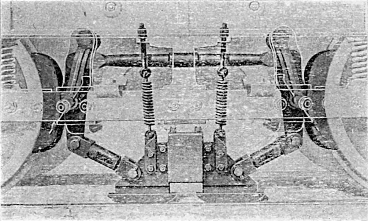
Fig. 56. Magnetic Brake Shoe.
Westinghouse Electromagnetic Brake. The Westinghouse magnetic brake is in principle similar to the General Electric brake as far as the use of motors as generators is concerned; but, instead of assisting the motors by means of a magnetic brake disc acting against the car wheel, a magnetic brake shoe is used (see Fig. 56), which acts against both car wheel and track. This not only retards through the medium of the wheels but acts directly on the track. It is not dependent upon the coefficient of friction between the wheels and track; and it should, therefore, be possible to stop much more quickly than with any form of brake depending upon the coefficient of friction between the wheels and track.
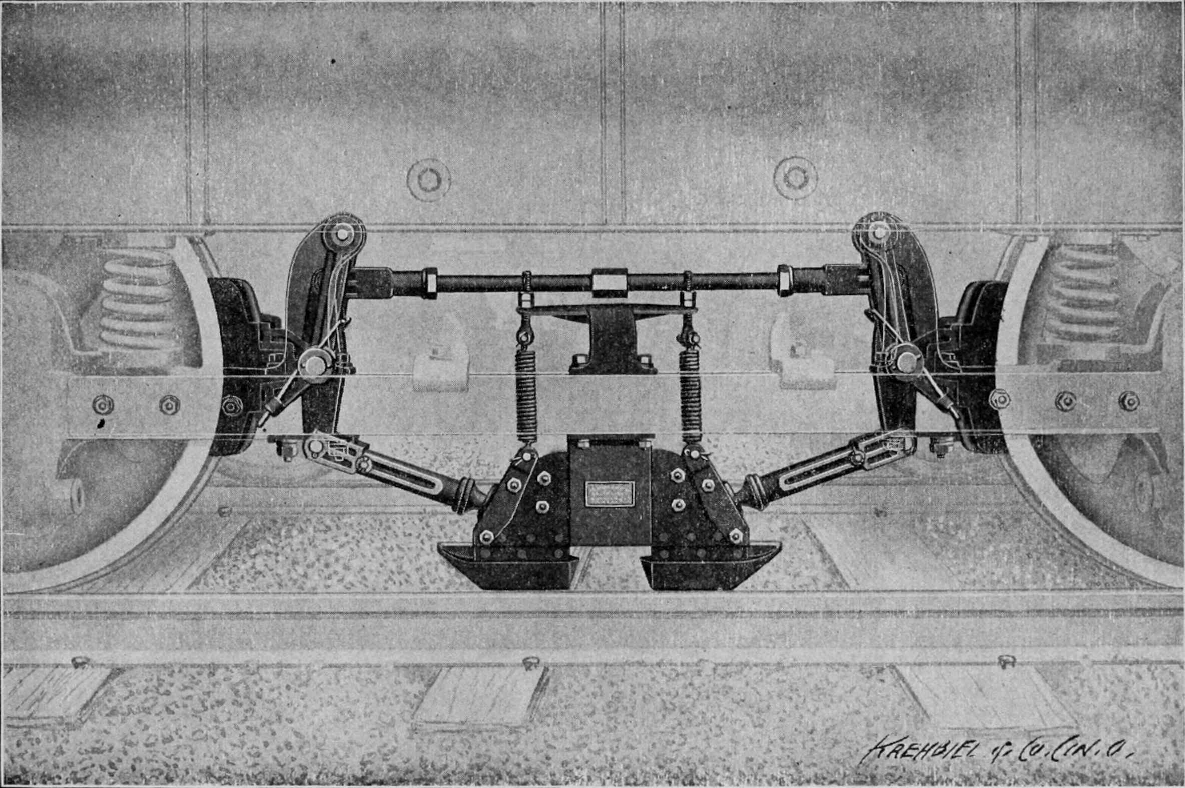
MAGNETIC BRAKE SHOWING METHOD OF ATTACHING TO CAR FRAME AND TRUCKS.
Westinghouse Air Brake Co.
Track Brakes. Track brakes have been used to some extent on very hilly electric roads. These have a shoe fastened to the truck frame, which acts directly on the track.
Motors as Emergency Brakes. The motors can of course be used to brake the car by simply reversing them if current is applied to them from the line. But in case the trolley flies off or if the circuit breaker or the fuse opens the circuit, or the supply of current is interrupted for any other reason, they may be used as brakes by throwing the reverse lever and moving the controller handle to the multiple position of a two-motor equipment or by simply throwing the reverse lever of a four-motor equipment. These movements throw the motors in multiple and connect the fields and armatures of the motor in such relation that they can generate current. One of the motors then acts similarly to a generator in a power house, deriving its power from the momentum of the moving car instead of from an engine, and sends current through the other motor of the pair which acts like any auxiliary motor trying to revolve its wheels in the opposite direction from that in which they are revolving. The motors of a four-motor equipment are permanently connected in two multiple groups as long as the reverse is not in the central position. In the two motor equipment such connections are not made until the controller handle is turned to the multiple position. As the external resistance is beyond the junction of the two motor circuits, the braking effect is not increased by cutting out the resistance.
The difference in the residual magnetism of the fields or in the magnetic qualities of the fields of the two motors is primarily the cause of the generation of the current. The motors at first act in opposition, but one of them generates the higher voltage and forces a current through the other. This current overcomes the residual magnetism of the second motor, thereby changing its polarity and both motors then act in series to send the current through the low resistance path afforded by the windings. Any current passing increases the strength of the fields and consequently the voltages, so that abnormal currents are generated and the braking action is consequently severe.
This generating action does not take place before the reverse lever is thrown because the connections of the armatures and fields are such that any current generated by reason of the residual magnetism of the fields, flows in such a direction through these that this magnetism is destroyed. The current then ceases to flow. This explains why current is not generated in No. 2 motor with a K type of controller during the change-over period when it is short-circuited, or in equipments when the trolley flies off and the controller is turned on.
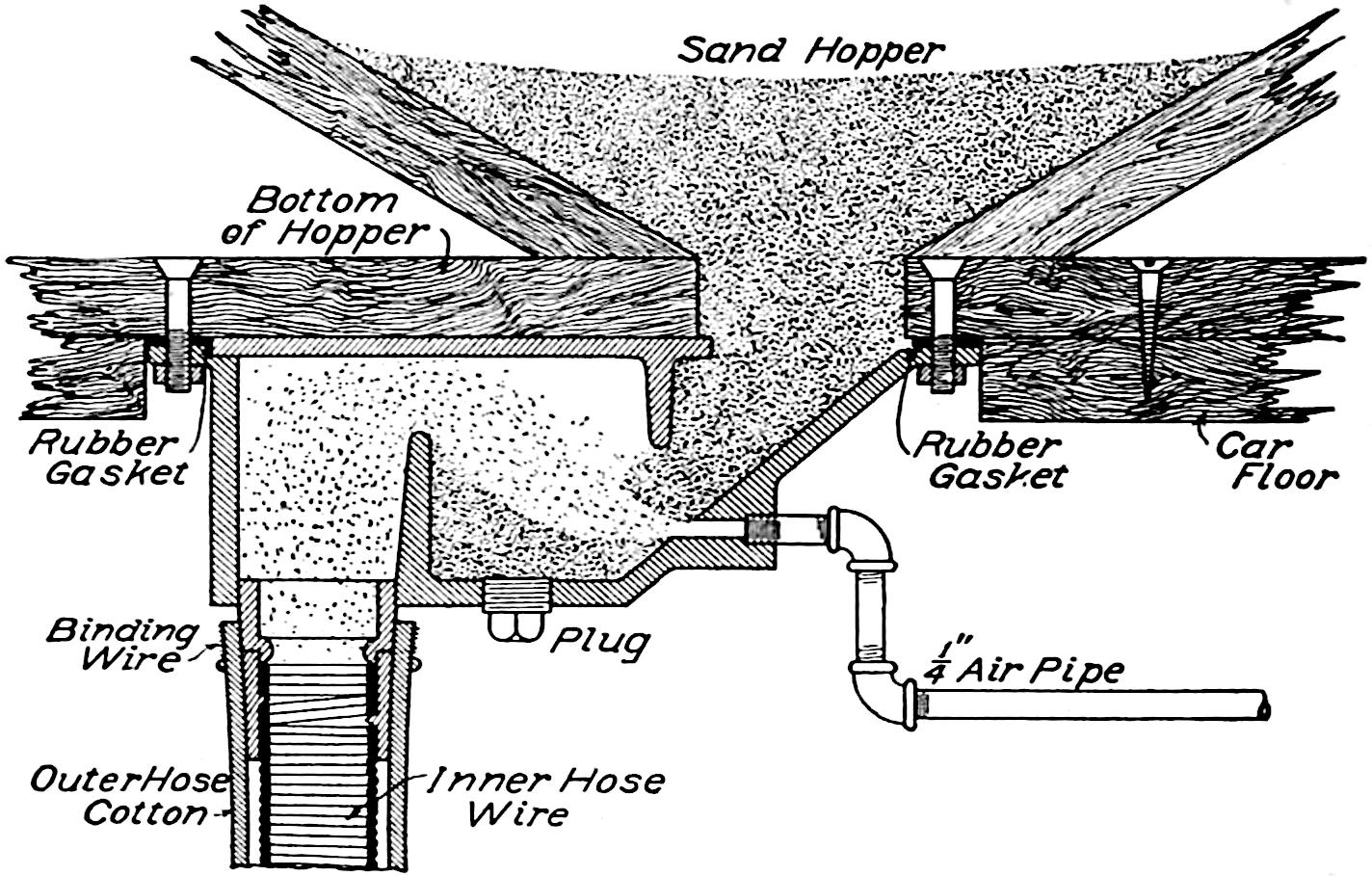
Fig. 57. Pneumatic Sander.
Brake Shoes. The subject of brake shoes is of very little importance on the smaller cars traveling at slow speeds and controlled alone by hand brakes. On the larger high speed interurban cars, the brake shoe question becomes an important item because of the rapidity with which they are worn away. On such cars shoes sometimes last but about one week. This means eight shoes per week per car or an expense of about $4.00 per car per week.
Brake shoes are usually of soft gray cast iron with inserts of steel, although some companies use very hard iron. They are usually fastened by means of a key to a brake shoe head permanently attached to the brake rigging. The brake levers are so adjusted that the shoes clear the wheels about ³⁄₁₆-inch when the brakes are released. This distance increases as the shoes wear, so that the brakes must be adjusted frequently to take up the slack and prevent waste of air.
Track Sanders. A sprinkling of sand on the rail increases wonderfully the adhesion of the rail and wheel. There is usually on cars some provision made for scattering sand on the rails immediately in front of the leading wheels. From sand boxes placed under the seats in the smaller cars, or on the truck of the larger ones, flexible hose or pipes drop within an inch or two of the rail in front of the leading wheels. A valve under the control of the motorman regulates the flow of sand to the rail. Sometimes air pressure is used to blow the sand out of the sand box into the hose. In this case air pressure is obtained from the air brake system, and an air valve leading to the sand box is placed in the motorman’s cab. A section through a pneumatic sander of this kind is shown in Fig. 57.
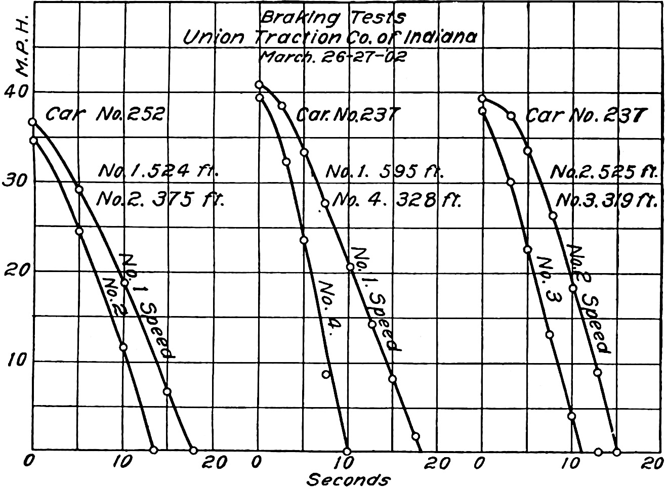
Fig. 58. Curves of Braking Tests.
Coefficient of Friction. It has been found by experiment that the coefficient of friction between the car wheel and rail is about 25 per cent of the weight on the wheel when the rails are dry; that is, a car wheel having a weight of 2,000 pounds upon it would not be able to exert either an accelerating or a retarding force exceeding 25 per cent of this, or 500 pounds. This is when the wheel is rolling. There is apparently a kind of locking or inter-meshing of the rough surfaces of wheel and rail when the wheel is rolling, because it is found that when a wheel begins to skid or slide, the coefficient of friction falls off about two-thirds. The maximum braking or retarding force that can be obtained, therefore, in a dry rail, amounts to 25 per cent of the weight of the car. If the rail is slippery this is much reduced; or if the wheels are allowed to slide it is also much reduced. If more retarding force than can be obtained through the medium of a wheel rolling on the rail is desired, it must be obtained either by the track brakes or by magnetism.
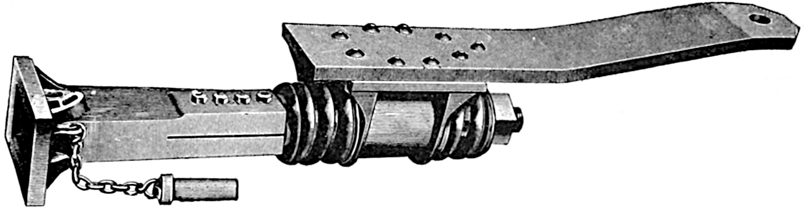
Fig. 59. Automatic Coupler.
Rate of Retardation in Braking. The rate of retardation of cars in braking is usually 1 to 2 miles per hour per second. In other words a car going at a speed of 40 miles an hour will usually be stopped in 40 to 20 seconds.
The plotted results of some braking tests (Fig. 58) show a higher rate of acceleration. These tests were made on an interurban car weighing about 63,000 pounds, equipped with straight air brakes. Of the six curves shown, that giving the highest rate of retardation is No. 4. This shows a stop from a speed of 38 miles per hour in 9½ seconds or a rate of retardation of about 4 miles per hour per second. All of the curves shown are for emergency stops. They show about the highest rate of retardation that could be made with the equipment.
Drawbars and Couplers. For small surface cars a crude drawbar is usually provided consisting simply of a straight iron bar pivoted under the car and provided with a cast-iron pocket near the end. A coupling pin passing through the pocket of one coupler and through a hole in the end of the bar of the other, holds the two cars together.
The requirements of a coupler for heavier cars such as those used on interurban and elevated roads are more exacting. The ends of the bars are usually pivoted under the car about five feet back from the bumper. A spring cushion intervenes between the pivot point and the drawbar head. The illustrations, Figs. 59 and 60, show the action of the Van Dorn Automatic coupler, which is the one used by all the elevated lines in the United States. The link is placed in one of the drawbar heads and the pin in the other. As the cars come together the wedge-shaped end of the link forces its way between the pin and a spring. When the faces of the drawbar heads meet, the spring forces the link to engage the pin. The mechanism is designed especially to prevent lost motion between coupler heads because, unlike steam railroad drawbars, electric car drawbars must swivel to round curves and a great amount of play at the point of coupling with swiveling drawbars would allow the couplers to bend under a pushing strain.
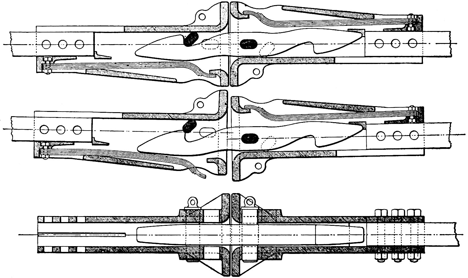
Fig. 60.