UPON THE RESISTANCE OF THE AIR TO BODIES OF DIFFERENT FORMS.
Reading edition
Difficulties of the question.
The influence of the form of a body upon the resistance offered to it by a fluid, is a problem of the greatest difficulty; and although the most celebrated mathematicians have turned their attention to the subject, still, even for slow motions, they have only been able to frame strictly empirical formula, founded upon the data derived from practice; while with regard to the resistance at very high velocities, such as we have to deal with, very little light has hitherto been thrown upon the subject.
Compressed fluid.
When a body moves in the atmosphere, the particles which are set in motion by the projectile, act upon those in proximity to them, and these again upon others; and also from the elasticity of the fluid, it would be compressed before the body in a degree dependant upon the motion and form of the body. Moreover, the atmosphere itself partakes so much of the nature of an infinitely compressed fluid, as to constantly follow the body without loss of density when the motion is slow, but not when the velocity is great, so that the same law will not hold good for both. In an infinitely compressed fluid (that is, one which would fill up the space left behind the body instantaneously) the parts of the fluid which the body presses against in its motion would instantaneously communicate the pressure received by them throughout the whole mass, so that the density of the fluid would not undergo any change, either in front of the body or behind it, consequently the resistance to the body would be much less than in a fluid partially compressed like the atmosphere; and the form of the body would not have the same effect in diminishing or increasing the amount of resistance.
When a vacuum is formed behind the ball.
When the velocity of a body moving in the atmosphere is so great that a vacuum is formed behind it, the action of the fluid approaches to that of the discontinued fluid.
RESULTS OF EXPERIMENTS WITH SLOW MOTIONS.
Resistance in proportion to surface.
1st. It appears from the various experiments that have been made upon bodies moving in the atmosphere, that the resistance is nearly as the surface, increasing a very little above that proportion in the greater surfaces.
Resistance as squares of velocity.
2nd. That the resistance to the same surface with different velocities, is in slow motions nearly as the squares of the velocity, but gradually increasing more and more in proportion as the velocities increase.
Rounded and pointed ends suffer less resistance.
3rd. The round ends, and sharp ends of solids, suffer less resistance than the flat or plane ends of the same diameter. Hence the flat end of the cylinder and of a hemisphere, or of a cone, suffer more resistance than the round or sharp ends of the same.
Sharp ends not always least resistance.
4th. The sharper ends have not always the smaller resistances; for instance, the round end of a hemisphere has less resistance than the pointed end of a cone, whose angle with the axis is 25° 42′.
Form of base affects resistance.
5th. When the hinder parts of bodies are of different forms, the resistances are different, though the fore parts are the same. Hence the resistance to the fore part of a cylinder is less than that on the equally flat surface of the cone or hemisphere, owing to the shape of the base of the cylinder. The base of the hemisphere has less resistance than the cone, and the round side of the hemisphere less than that of the whole sphere.
Only proved for slow motions.
The above refers only to slow motions, and the results given, from experiments with very small velocities; and it is to be expected, that with very rapid motions the form of the fore, as well as the hind part, of the projectile, will influence the amount of resistance in a much higher degree.
Form of hind part.
That form for the hind part will be best which has the greatest pressure upon it, when moving with a certain velocity.
Best shape for fore and hind part.
The ogivale form seems, from experiment, to fulfil the former condition. The best form for the hind part, for rapid motions, has not been determined; it may, however, be considered to be of much less importance than the shape of the fore part.
Form determined by extent of range.
Of course the best form can be determined by extent of range, but deductions from this will depend upon such a variety of circumstances, the effects of some of which must be entirely hypothetical, that the correctness of any formulæ obtained in this manner must be very uncertain.
Form suggested by Sir I. Newton.
Sir Isaac Newton, in his “Principia,” has given an indication of that form of body, which, in passing through a fluid, would experience less resistance than a solid body of equal magnitude of any other form. It is elongated.
Axis of elongated bodies must be fixed.
It is plain, however, that the minimum of resistance would not be obtained with a shot of an elongated form, unless the axis can be kept in the direction of the trajectory; as not only will the axis perpetually deviate from the true direction, but the projectile will turn over and rotate round its shorter axis, that is, if fired out of a smooth bore.
Advantages of conical bullets.
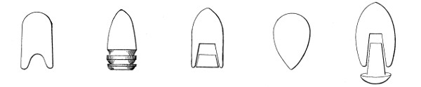
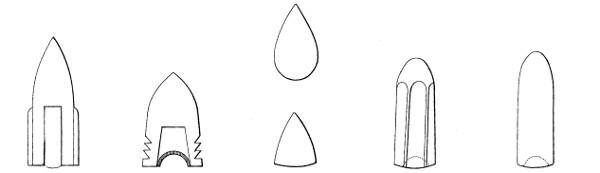
Conical bullets have an advantage, from their pointed end, which enables them to pass through the air with greater facility; and for the same reason they are better calculated to penetrate into any matter than spherical ones.
Disadvantages of conical bullets.
A solid bullet cannot be pointed without sending backward the centre of gravity. The sharper the point, the more it is liable to injury, and if the apex of the cone does not lie true, in the axis of the projectile, then such an imperfection of figure is calculated to cause greater deflections in the flight than any injury which a round surface is likely to sustain. In penetrating into solid bodies, it is also important that the centre of gravity should be near its work.
RESISTANCE OF THE AIR, AS AFFECTED BY THE WEIGHT OF PROJECTILES.
Resistance overcome by weight.
Bodies of similar volume and figure overcome the resistance of the air in proportion to their densities. The amount of the air’s resistance is in proportion to the magnitude of the surface.
Contents of circles.
The superficial contents of circles are as the squares of their diameters. Hence if the ball A. (plate 23, fig. 3) be 2in. in diameter, and the ball B. 4in., the amount of resistance experienced would be as four to sixteen.
Contents of spheres.
The cubical contents, or weights of spheres, are in proportion to the cubes of their diameters. Hence the power to overcome resistance in the balls A and B would be as eight to sixty-four. Thus the power to overcome resistance increases in much greater proportion than the resistance elicited by increasing the surface.
Advantages of elongated bullets.
Suppose an elongated body to have the diameter of its cylindrical portion equal to that of the ball A., i.e., E.F. = C.D., (plate 23, fig. 4), and elongated so that its weight should be equal to that of the spherical shot B., it is evident that it would meet equal resistance from the air, to the ball A., having, at the same time, as much power to overcome resistance as the body B.
Elongated balls, by offering a larger surface to the sides of the barrel, are less liable to be affected by any imperfections in the bore; whereas the spherical ball, pressing only on its tangential point, will give to any little hollows, or undulations, wherever they occur.
Balls cannot be expanded.
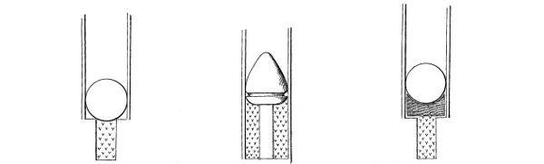
A spherical ball cannot be expanded into the grooves, unless there be very little windage, except by blows from the ramrod, the gas escaping round the circumference of the ball, and giving it an irregular motion while passing down the barrel; Elongated projectiles easily expanded.but an elongated projectile can be readily expanded, and the facility of doing so is in proportion to the difference of length between its major and minor axis.
DEVIATIONS OF PROJECTILES FROM SMOOTH-BORED GUNS.
Causes of deviation of shot.
Very great irregularities occur in the paths described by projectiles fired from smooth-bored guns. It is a fact well known to all practical artillerists, that if a number of solid shot or any other projectile be fired from the same gun, with equal charges and elevations, and with gunpowder of the same quality, the gun carriage resting on a platform, and the piece being laid with the greatest care before each round, very few of the shot will range to the same distance; and moreover, the greater part will be found to deflect considerably (unless the range be very short) to the right or left of the line in which the gun is pointed.
Four causes of deviation.
The causes of these deviations may be stated as follows:—1st, Windage; 2nd, Rotation; 3rd, Wind; 4th, from Rotation of the Earth.
1st CAUSE, WINDAGE.
Action from windage.
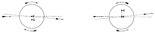
Windage causes irregularity in the flight of a projectile, from the fact of the elastic gas acting in the first instance on its upper portion, and driving it against the bottom of the bore; the shot re-acts at the same time that it is impelled forward by the charge, and strikes the upper surface of the bore some distance down, and so on by a succession of rebounds, False direction.until it leaves the bore in an accidental direction, and with a rotatory motion, depending chiefly on the position of the last impact against the bore. Thus should the last impact of a (concentric) shot when fired from a gun be upon the right hand side of the bore, as represented, (plate 23, fig. 5); the shot will have a tendency to deflect to the left in the direction. Gives rotation.While at the same time a rotation will be given to it in the direction indicated by the arrows.
2nd CAUSE, ROTATION.
Rotation without translation.
Every body may have a twofold motion, one by which it is carried forward, and the other by which it may turn round on an axis passing through its centre, called a motion of rotation.
When a body has only a motion of translation all the particles of which it is composed move with equal swiftness, and also in parallel directions; and by the first law of motion, every particle put in such motion will constantly move with the same velocity in the same direction, unless it be prevented by some external cause.
Rotation.
By a motion of rotation, a body without changing its place, turns round on an axis passing through its centre of gravity. Rotation and translation combined.A body may have at the same time both a progressive and rotatory motion, without either disturbing the other, and one may suffer a change from the action of some external force, while the other continues the same as before.
Force through centre of gravity, causes progressive motion only.
If the direction of the force be through the centre of gravity, it causes a progressive motion only, that is, if the body was at rest before, it will move forward in the direction of the impressed force.
Effect of force on a body in motion.
If a body had a progressive motion before, then impressed force will cause it to move faster or slower, or to change its direction, according as the direction of this second force conspires with or opposes its former motion, or acts obliquely on its direction.
Rotation not disturbed by second force in direction of centre of gravity.
If a body, besides its progressive motion had a motion of rotation also, this last will not be changed by the action of a new force passing through the centre of gravity.
Rotation of force does not pass through the centre of gravity.
If the direction of the force does not pass through the centre of gravity, the progressive motion will be altered, and the body will then also acquire a rotatory motion round an axis passing through the centre of gravity, and perpendicular to a plane passing through the direction of the force and this centre.
CASES BEARING UPON THE FOREGOING THEORY.
When ball is perfectly round, centre of gravity coincides with figure, and no windage.
1st Case. Suppose the ball to be perfectly round, its centre of gravity and figure to coincide, and let there be no windage. In this case the force of the powder not only passes through the centre of gravity of the shot, but proceeds in a direction parallel to the axis of the bore, and there would be but small friction due to the weight of the shot.
If windage then rotation.
2nd Case. But as there is a considerable amount of friction between the bore and the projectile in the case where there is windage, the direction of this force being opposite to that of the gunpowder, and upon the surface of the ball, it will therefore give rotation to the shot.
Eccentricity causes rotation.
3rd Case. Suppose the ball to be perfectly round, but its centre of gravity not to coincide with the centre of figure. In this case the impelling force passes through the centre of the ball, or nearly so, and acts in a direction parallel to the axis of the piece; but if the centre of gravity of the ball lie out of the line of direction of the force of the powder, the shot will be urged to turn round its centre of gravity.
Angular velocity.
The angular velocity communicated to the body will depend, firstly, upon the length of the perpendicular from the centre of gravity upon the direction of the impelling force, and secondly, upon the law of density of the material or the manner in which the metal is distributed. The direction of rotations will depend upon the position of the centre of figure with regard to that of gravity. (Plate 23, fig. 6.)
Robins’ remarks.
Robins remarks, bullets are not only depressed beneath their original direction by the action of gravity, but are also frequently driven to the right or left of that direction by the action of some other force. If it were true that bullets varied their direction by the action of gravity only, then it ought to happen that the errors in their flight to the right or left of the mark, should increase in proportion to the distance of the mark from the firer only.
Deflection not in proportion to distance.
But this is contrary to all experience, for the same piece which will carry its bullet within an inch at ten yards, cannot be relied upon to ten inches in one hundred yards, much less to thirty inches in three hundred.
Now this irregularity can only arise from the track of the bullet being incurvated sideways as well as downwards. The reality of this doubly incurvated track being demonstrated, it may be asked what can be the cause of a motion so different from what has been hitherto supposed.
1st cause of increase, deflection.
1st Cause. Is owing to the resistance of the air acting obliquely to the progressive motion of the body, and sometimes arises from inequalities in the resisted surface.
2nd cause, from whirling motion.
2nd Cause. From a whirling motion acquired by the bullet round its axis, for by this motion of rotation, combined with the progressive motion, each part of the bullet’s surface will strike the air in a direction very different from what it would do if there was no such whirl; and the obliquity of the action of the air arising from this cause will be greater, according as the rotatory motion of the bullet is greater in proportion to its progressive motion; and as this whirl will in one part of the revolution conspire in some degree with the progressive, and in another part be equally opposed to it, the resistance of the air on the fore part of the bullet will be hereby affected, and will be increased in that part where the whirling motion conspires with the progressive; and diminished where it is opposed to it. Direction of a shot influenced by position of axis round which it whirls.And by this means the whole effort of resistance, instead of being in a direction opposite to the direction of the body, will become oblique thereto, and will produce those effects we have already mentioned. For instance, if the axis of the whirl was perpendicular to the horizon, then the incurvation would be to the right or left. If that axis were horizontal to the direction of the bullet, then the incurvation would be upwards or downwards. But as the first position of the axis is uncertain, and as it may perpetually shift in the course of the bullet’s flight, the deviation of the bullet is not necessarily either in one certain direction, nor tending to the same side in one part of its flight that it does in another, but it more usually is continually changing the tendency of its deflection, as the axis round which it whirls must frequently shift its position during the progressive motion.
Doubly incurvated track.
It is constantly found in practice that a shot will deviate in a curved line, either right or left, the curve rapidly increasing towards the end of the range. This most probably occurs from the velocity of rotation decreasing but slightly, compared with the initial velocity of the shot, or, if a strong wind is blowing across the range during the whole time of flight, the curve would manifestly be increased according as the velocity of the ball decreased.
ILLUSTRATIONS OF ROBINS’ THEORY OF ROTATION.
With ball and double string.
1st Illustration. A wooden ball 41⁄2 inches in diameter suspended by a double string, nine feet long. It will be found that if this ball receive a spinning motion by the untwisting of the string it will remain stationary. If it be made to vibrate, it will continue to do so in the same vertical plane. But if it be made to spin while it vibrates it will be deflected to that side on which the whirl combines with the progressive motion.
By firing through screens.
2nd Illustration. By firing through screens of thin paper placed parallel to each other, at equal distances, the deflection or track of bullets can easily be investigated. It will be found that the amount of deflection is wholly disproportioned to the increased distance of the screens.
Bent muzzle.
3rd Illustration. To give further light upon this subject, Mr. Robins took a barrel and bent it at about three or four inches from the muzzle to the left, the bend making an angle of 3° or 4° with the axis of the piece.
By firing at screens it was found that although the ball passed through the first screens to the left, it struck the butt to the right of the vertical plane on which aim was taken in line of the axis of the unbent portion of the barrel. This was caused by the friction of the ball on the right side of the bent part of the muzzle, causing the ball to spin from left to right.
ON ECCENTRIC PROJECTILES.
How to find centre of gravity.
Sir Howard Douglas, in his “Naval Gunnery,” states:—“The position of the centre of gravity can be found by floating the projectile in mercury, and marking its vertex. Then mark a point upon the shot diametrically opposite to that point, which will give the direction of the axis in which the two centres lie. Thus the shot can be placed in the gun with its centre of gravity in any desired position.”
“On making experiments, it appeared that not one shot in a hundred, when floated in mercury, was indifferent as to the position in which it was so floated, but turned immediately, until the centre of gravity arrived at the lowest point, and consequently that not one shot in a hundred was perfect in sphericity, and homogeneity. Shells can be made eccentric by being cast with a solid segment in the interior sphere, left in the shell, or by boring two holes in each shell, diametrically opposite to one another, stopping up one with 5lbs. of lead, and the other with wood. Effect of eccentricity.When the centre of gravity was above the centre of the figure, the ranges were the longest, and when below, the shortest. When to the right or left hand, the deviations were also to the right or left. The mean range which, with the usual shot, was 1640 yards, was, with the shot whose centres of gravity and of figure were not coincident, the centre of gravity being upwards, equal to 2140 yards, being an increase of 500 yards.
Ricochet of eccentric shot.
“With respect to the ricochet of eccentric spherical projectiles, the rotation which causes deflection in the flight, must act in the same manner to impede a straight forward graze. When an ordinary well formed homogenous spherical projectile, upon which probably very little rotation is impressed, makes a graze, the bottom of the vertical diameter first touches the plane, and immediately acquires, by the reaction, a rotation upon its horizontal axis, by which the shot rolls onwards throughout the graze, probably for a straight forward second flight. But in the case of an eccentric spherical projectile, placed with its centre of gravity to the right or to the left, its rotation upon its vertical axis during the graze must occasion a fresh deflection in its second flight, and it is only when the centre of gravity is placed in a vertical plane passing through the axis of the gun, that the rotation by touching the ground will not disturb the direction of the graze, though the extent of range to the first graze will be affected more or less according as the centre of gravity may have been placed upwards or downwards. Whether the rebounds take place from water, as in the experiments made on board the “Excellent,” or on land, as those carried on at Shoeburyness, the shot, when revolving on a vertical axis, instead of making a straight forward graze, suffered deflection which were invariably towards the same side of the line of fire as the centre of gravity; and at every graze up to the fourth, a new deflection took place.
Knowledge derived from experiments with eccentric shot.
“The results of these very curious and instructive experiments fully explain the extraordinary anomalies, as they have heretofore been considered, in length of range and in the lateral deviations: these have been attributed to changes in the state of the air, or the direction of the wind, to differences in the strength of the gunpowder, and to inequalities in the degrees of windage. All these causes are, no doubt, productive of errors in practice, but it is now clear that those errors are chiefly occasioned by the eccentricity and nonhomogeneity of the shot, and the accidental positions of the centre of gravity of the projectile with respect to the axis of the bore. The whole of these experiments furnish decisive proof of the necessity of paying the most scrupulous attention to the figure and homogeneity of solid shot, and concentricity of shells, and they exhibit the remarkable fact that a very considerable increase of range may be obtained without an increase in the charge, or elevation of the gun.”
No advantage in using eccentric projectiles.
It is not to be expected that eccentric projectiles would be applicable for general purposes, on account of the degree of attention and care required in their service, nor would much advantage be gained by their use, as the momentum is not altered, and it is only necessary to give the ordinary shot a little more elevation in order to strike the same object.
Range of elongated projectiles at certain low elevations greater in air than in vacuo.
There is another point of great importance with regard to the range of elongated projectiles. It is asserted by Sir W. Armstrong and others, that at certain low elevations the range of an elongated projectile is greater in the atmosphere than in vacuo, and the following is the explanation given by the former of this apparent paradox. “In a vacuum, the trajectory would be the same, whether the projectile were elongated or spherical, so long as the angle of elevation, and the initial velocity were constant; but the presence of a resisting atmosphere makes this remarkable difference, that while it greatly shortens the range of the round shot, it actually prolongs that of the elongated projectile, provided the angle of elevation do not exceed a certain limit, which, in my experiments, I have found to be about 6°. This appears, at first, very paradoxical, but it may be easily explained. The elongated shot, if properly formed, and having a sufficient rotation, retains the same inclination to the horizontal plane throughout its flight, and consequently acquires a continually increasing obliquity to the curve of its flight. Now the effect of this obliquity is, that the projectile is in a measure sustained upon the air, just as a kite is supported by the current of air meeting the inclined surface, and the result is that its descent is retarded, so that it has time to reach to a greater distance.”
Charge.
The form and weight of the projectile being determined as well as the inclination of the grooves, the charge can be so arranged as to give the necessary initial velocity, and velocity of rotation; or if the nature of projectile and charge be fixed, the inclination of the grooves must be such as will give the required results. The most important consideration is the weight and form of projectile; the inclination of the grooves, the charge, weight of metal in the gun, &c., are regulated almost entirely by it. The charges used with rifle pieces are much less than those with which smooth-bored guns are fired, for little or none of the gas is allowed to escape by windage, there being therefore no loss of force; and it is found by experience that, with comparatively low initial velocities, the elongated projectiles maintain their velocity, and attain very long ranges.
Note.—The foregoing articles on “Theory,” are principally extracted from “New Principles of Gunnery by Robins,” “Treatise on Artillery, by Lieut.-Colonel Boxer, R.A.” “The Rifle Musket, by Captain Jervis, M.P., Royal Artillery.” “Elementary Lecturers on Artillery, by Major H. C. Owen and Captain T. Dames, Royal Artillery.”
THE END.
PLATE 1.
FIG. 1.
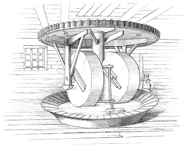
Powder Mill.
FIG. 2.
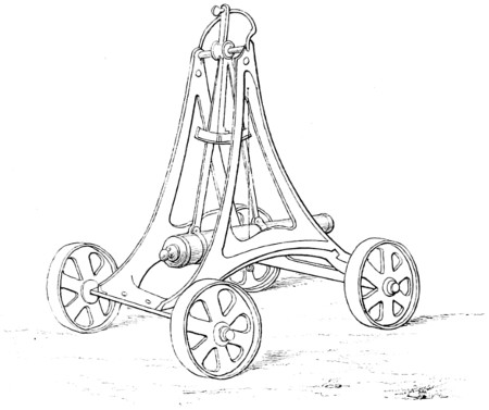
Old Eprouvette Pendulum
FIG. 3.
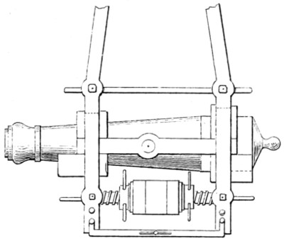
New Pattern Eprouvette
Harry Vernon delt.
Day & Son Lithrs. to the Queen.
PLATE 2.
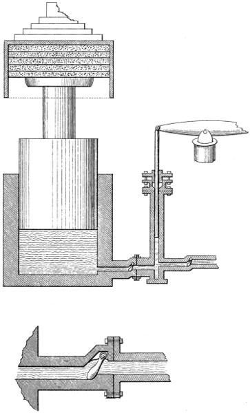
Enlarged section of Valve
Hydraulic Press
Harry Vernon delt.
Day & Son Lithrs. to the Queen.
PLATE 3.
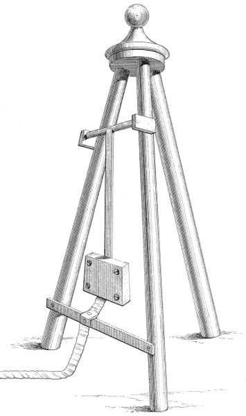
Robins’ Balistic Pendulum
Harry Vernon delt.
Day & Son Lithrs. to the Queen.
PLATE 4.
FIG. 1.
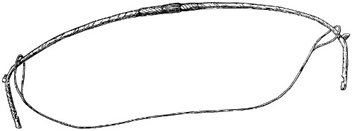
Bow unstrung
FIG. 2.
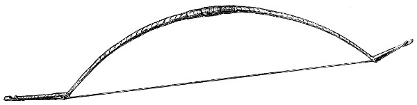
Bow strung
FIG. 3.
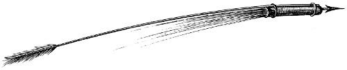
Hand or Arrow Rocket
FIG. 4.
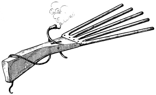
Five barrelled Matchlock
FIG. 5.
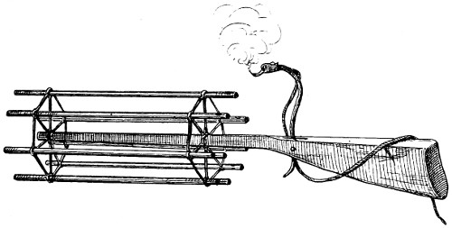
Revolving Barrelled Matchlock
CHINESE EXPLOSIVE AND OTHER WEAPONS.
FIG. 6.
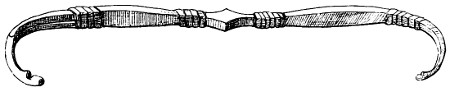
Asiatic Bow
Harry Vernon delt.
Day & Son Lithrs. to the Queen
PLATE 5.
FIG. 1.
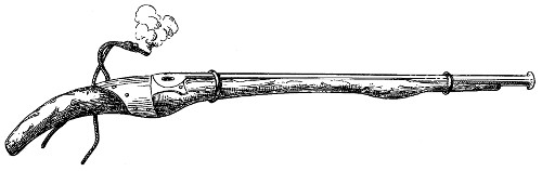
Matchlock
FIG. 2.
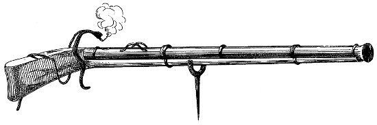
Breech loading Gingal (Chamber in)
FIG. 3.
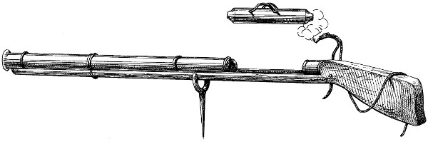
Breech loading Gingal (Chamber out)
CHINESE EXPLOSIVE ARMS.
Harry Vernon delt.
Day & Son Lithrs. to the Queen.
PLATE 6.
FIG. 1.
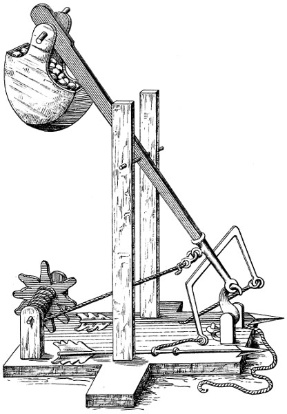
FIG. 2.
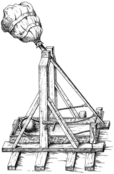
FIG. 3.
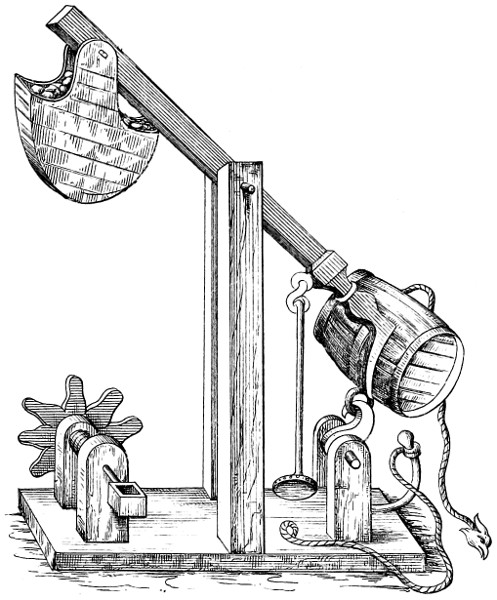
FIG. 4.
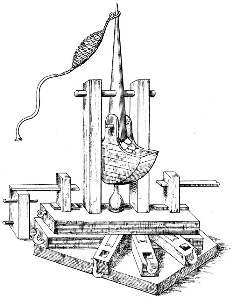
Harry Vernon dele.
MACHINES FOR THROWING DARTS AND STONES.
Day & Son Lithrs. to the Queen.
PLATE 7.
ONAGER (SLUNG).
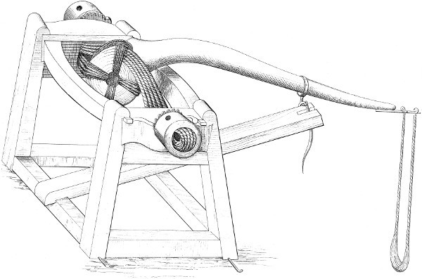
Harry Vernon delt.
Day & Son, Lithrs. to the Queen.
PLATE 8.
Onager (unslung).
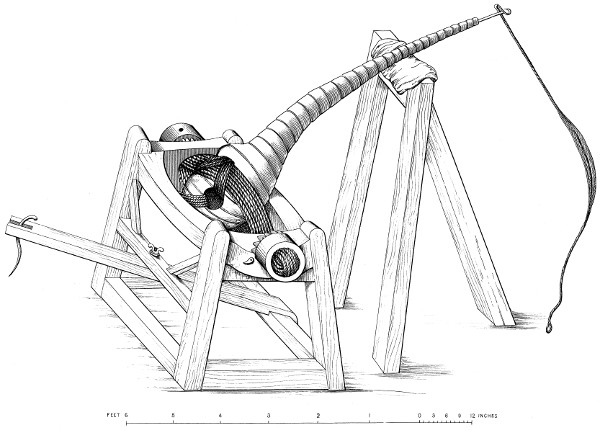
Harry Vernon delt.
Day & Son Lithrs. to the Queen.
Larger illustration
PLATE 9.
Balista
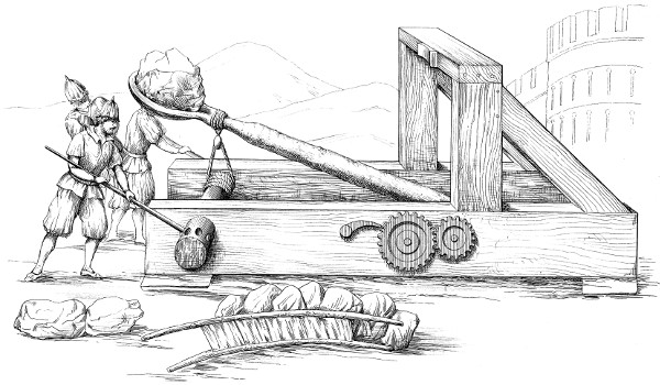
Arthur Walker C.t 79.th delt.
Day & Son Lithrs. to the Queen.
PLATE 10.
Catapulta.
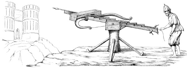
Dessiné par Arthur Walker.
Day & Son Lithrs. to the Queen.
PLATE 11.
FIG. 1.
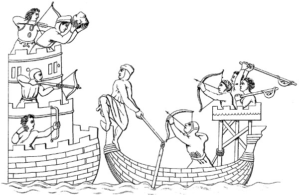
Staff slings, Longbows, Crossbows and Flail.
FIG. 2.
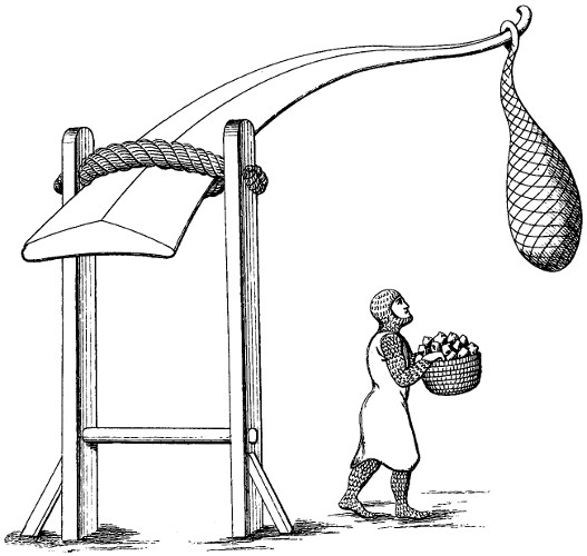
Onager.
FIG. 3.
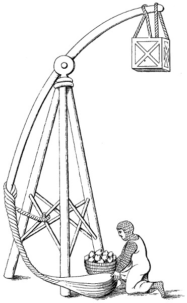
Trepied.
Harry Vernon delt.
Day & Son Lithrs. to the Queen.
PLATE 12.
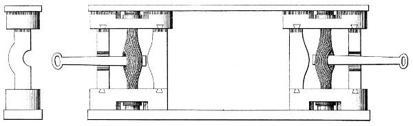
Detail of Springs.
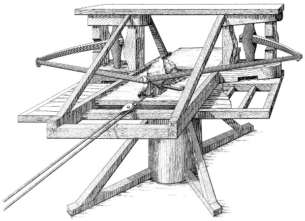
Balista.
Harry Vernon Staff Serjt. del.
Day & Son Lithrs. to the Queen.
PLATE 13.
FIG. 1. FIG. 2.
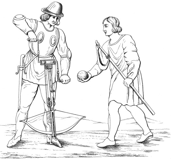
A Cross bow man and Slinger.
FIG. 3.
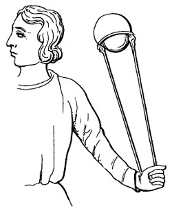
Harry Vernon delt.
Day & Son Lithrs. to the Queen.
PLATE 14.
FIG. 1.
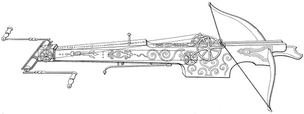
FIG. 2.
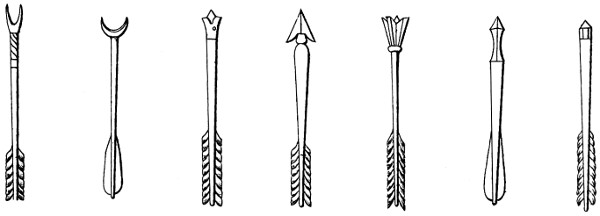
FIG. 3.
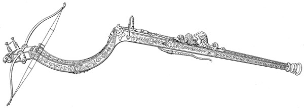
FIG. 4.

Cross-bows and Quarrels.
Harry Vernon delt.
Day & Son Lithrs. to the Queen.
Larger Fig. 1. Larger Fig. 3.
PLATE 15.
Harry Vernon delt.
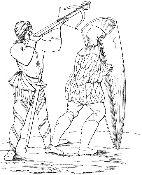
A Cross bow man and his Paviser.
Day & Son Lithrs. to the Queen.
PLATE 16.
FIG. 1.

Gun and Querrel Temp: Edward 3rd. Sloane Mss.
FIG. 2.
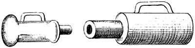
Small chambered Cannon from the Santini Mss.
FIG. 3.
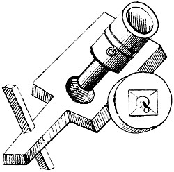
Santini Mss. Early part of 15th Centy.
FIG. 4.
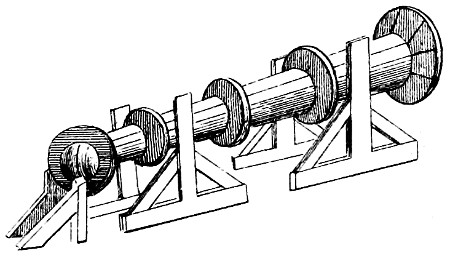
Mode of mounting from Froissart.
FIG. 5.
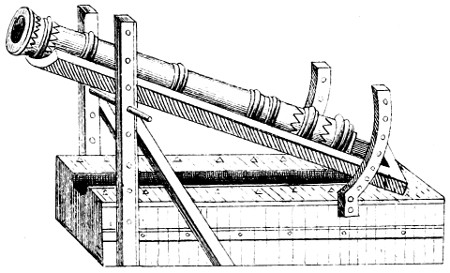
Method of obtaining elevation.
FIG. 6.
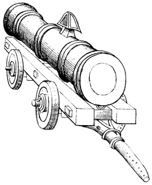
Mode of Mounting from Valturius.
FIG. 7.
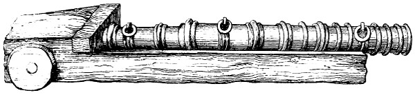
From the wreck of the “Mary Rose” Temp: Henry 8th.
FIG. 8.
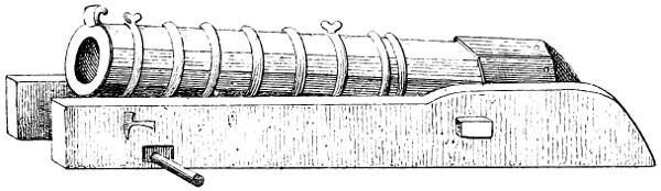
Hooped Cannon in wooden bed.
FIG. 9.
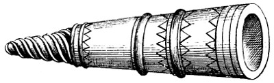
Ancient Screw piece.
FIG. 10.
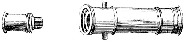
Ancient Screw Breech loader.
FIG. 11.

Chinese Field piece Peiho 1860.
FIG. 12.
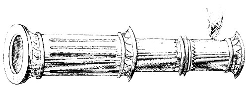
Ancient howitzer Cannon for throwing balls Filled with powder
Arthur Walker delt.
Day & Son Lithrs. to the Queen.
PLATE 17.
FIG. 1.

Giorgio Martini, 15th. Century, latter part.
FIG. 2.

Queen Elizabeth’s Pocket Pistol.
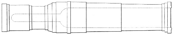
Mons Meg.

Chamber. Pierrier or Paterera__16th. Century.
H. Cautly del.
Day & Son Lithrs. to the Queen.
PLATE 18.
FIG. 1.
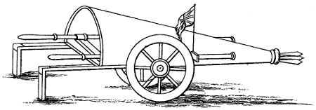
Cart of War.__Temp: Henry 8th.
FIG. 2.
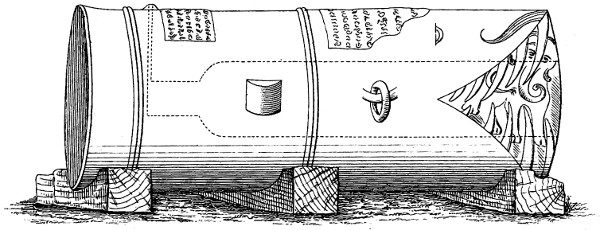
“Moolik i Meidan.”
FIG. 3.
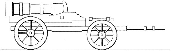
Bombard and Carriage.__15th. Centy.
FIG. 4.
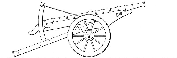
Long Serpentine of Wrought Iron.__15th. Centy.
R.G. Coles del.t
Day & Son Lithrs. to the Queen.
PLATE 19.
FIG. 1.
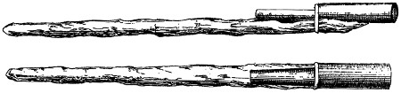
FIG. 2.

FIG. 7. FIG. 11. FIG. 12. FIG. 3. FIG. 4. FIG. 5. FIG. 8.
FIG. 6.
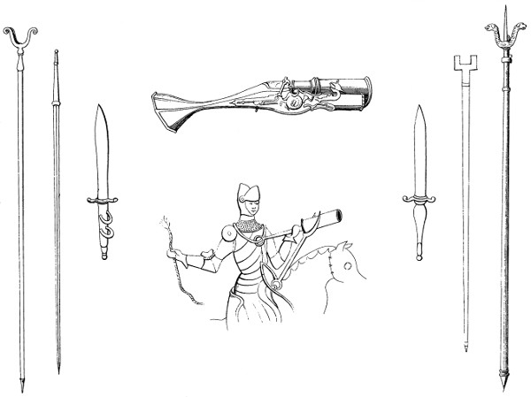
Larger Figs. 3-8, 11, 12
FIG. 9.
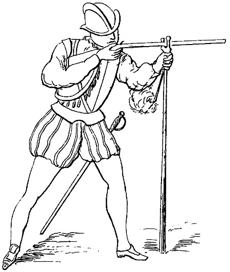
Musketeer 16th. Centy.
FIG. 10.
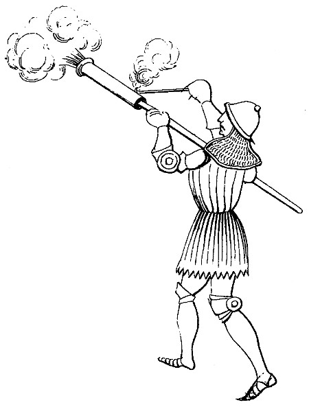
Earliest form of Hand Gun.
Arthur Walker, delt.
Day & Son Lithrs. to the Queen.
PLATE 20.
2 4 3
1 5 6 7 8

9 10 11 12 13
14 15 16 18 19
17
Day & Son Lithrs. to the Queen.
Larger Figs. 1-19
PLATE 21.
FIG. 1.
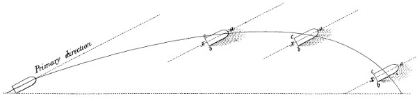
FIG. 2.

FIG. 3.
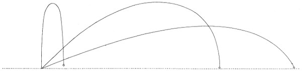
FIG. 4.

FIG. 5.

Arthur Walker del.
Day & Son Lithrs. to the Queen.
Larger Figs. 1-5
PLATE 22.
FIG. 1.

FIG. 2.

FIG. 3.
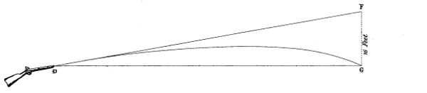
FIG. 4.
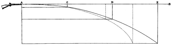
Arthur Walker Lt. 79th. del.
Day & Son Lithrs. to the Queen.
Larger Figs. 1-4
PLATE 23.
FIG. 1.
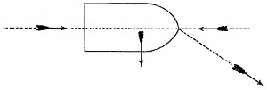
FIG. 2.
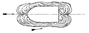
FIG. 3.
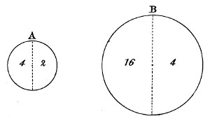
FIG. 4.
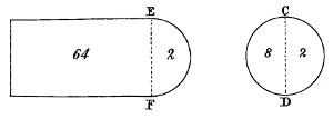
FIG. 5.

FIG. 6.
Harry Vernon Staff Serjt. del.
Day & Son Lithrs. to the Queen.
Larger Figs. 1-6