Chapter XII · (continued 2)
Reading edition
CENSORED
Maker’s Name and Model Num- ber of Cyl. Bore (In.) Stroke (In.) Piston Displace- ment (Cubic In.) H.P. R.P.M. Weight of Engine with Carburetor and Ignition Gas Consump- tion
Aeromarine 6 4 1⁄2 5 1⁄8 449 85 1400 440 ...
Aeromarine D-12 12 4 5⁄16 5 1⁄8 ... ... ... 750 ...
Curtiss OX 8 4 5 502 .6 90 1400 375 ...
Curtiss OXX-2 8 4 1⁄4 5 567 .5 100 1400 423 ...
Curtiss V-2 8 5 7 1100 200 1400 690 ...
CENSORED
General Vehicle Gnome Mono 9 4 .33 5 .9 848 100 1200 272 12 gals/hour at rated H.P.
Gyro K Rotary, Le Rhone Type 7 4 1⁄2 6 ... 90 1250 215 8 gals/hour at rated H.P.
Gyro L Rotary, Le Rhone Type 9 4 1⁄2 6 859 100 1200 285 10 gals/hour at rated H.P.
Hall-Scott A-7 4 5 7 550 90- 100 1400 410 ...
Hall-Scott A-5 6 5 7 825 125 1300 592 ...
Hispano-Suiza 8 4 5⁄8 5 672 154 1500 455 ...
Knox Motors Co. 12 4 3⁄4 7 1555 300 1800 1425 31.5 gals/hour
Maximotor A-6 6 4 1⁄2 5 477 85 1600 340 ...
Maximotor B-6 6 5 6 706 .8 115 1600 385 ...
Maximotor A-8 8 4 1⁄2 5 636 115 1600 420 ...
Packard 12 12 4 6 903 225 2100 800 ...
Sturtevant 5 8 4 5 1⁄2 552 .9 140 2000 580 ...
Sturtevant 5-A 8 4 5 1⁄2 ... 140 2000 514 13.75 gals/hour
Thomas 8 8 4 5 1⁄2 552 .9 135 2000 630 lbs. with self-starter ...
Thomas 88 8 4 1⁄8 5 1⁄2 552 .9 150 2100 525 lbs. with self-starter ...
Wisconsin 6 5 6 1⁄2 765 .7 140 1380 637 ...
Wisconsin 12 5 6 1⁄2 1531 .4 250 1200 ... ...
The carburetor used on this 150 horse-power Mercedes motor is precisely of the same type used on the Twin Six motor. It has two venturi throats, in the center of which is placed the gasoline spray nozzle of conventional type, fixed size orifices, immediately above which are placed two panel type throttles with side outlets. An idling or primary nozzle is arranged to discharge above the top of the venturi throat. The carburetor body is of cast aluminum and is water jacketed. It is bolted directly to air passage passing through the top and bottom half of the crank-case which passes down through the oil reservoir. The air before reaching the carburetor proper to some extent has cooled the oil in the crank chamber and has itself been heated to assist in the vaporization. The inlet pipes themselves are copper. All the passages between the venturi throat and the inlet valve have been carefully finished and polished. The only abnormal thing in the design of this motor is the short connecting rod which is considerably less than twice the stroke and would be considered very bad practice in motor car engines. A short connecting rod, however, possesses two very real virtues in that it cuts down height of the motor and the piston passes over the bottom dead center much more slowly than with a long rod.
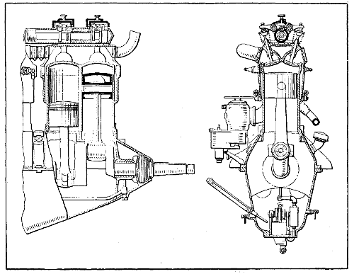
Fig. 245.—Part Sectional View of 90 Horse-Power Mercedes Engine, Which is Typical of the Design of Larger Sizes.
Other features of the design are a very stiff crank-case, both halves of which are bolted together by means of long through bolts, the crank-shaft main bearings are seated in the lower half of the case instead of in the usual caps and no provision is made for taking up the main bearings. The Mercedes company uses a plunger type of pump having mechanically operated piston valves and it is driven by means of worm gearing.
The overhead cam-shaft construction is extremely light. The cam-shaft is mounted in a nearly cylindrical cast bronze case and is driven by means of bevel gears from the crank-shaft. The vertical bevel gear shaft through which the drive is taken from the crank-shaft to the cam-shaft operates at one and one-half times the crank-shaft speeds and the reduction to the half-time cam-shaft is secured through a pair of bevels. On this vertical shaft there is mounted the water pump and a bevel gear for driving two magnetos. The water pump mounted on this shaft tends to steady the drive and avoid vibration in the gearing.
The cylinder sizes of six-cylinder aviation motors which have been built by Mercedes are
Bore Stroke Horse-power
105 mm. 140 mm. 100
120 mm. 140 mm. 135
140 mm. 150 mm. 150
140 mm. 160 mm. 160
The largest of these motors has recently had its horsepower increased to 176 at 1450 R. P. M. This general design of motor has been the foundation for a great many other aviation motor designs, some of which have proved very successful but none of which is equal to the original. Among the motors which follow more or less closely the scheme of design and arrangement are the Hall-Scott, the Wisconsin motor, the Renault water-cooled, the Packard, the Christofferson and the Rolls-Royce. Each of these motors show considerable variation in detail. The Rolls-Royce and Renault are the only ones who have used the steel cylinder with the steel jacket. The Wisconsin motor uses an aluminum cylinder with a hardened steel liner and cast-iron valve seats. The Christofferson has somewhat similar design to the Wisconsin with the exception that the valve seats are threaded into the aluminum jacket and the cylinder head has a blank end which is secured to the aluminum casting by means of the valve seat pieces. The Rolls-Royce motors show small differences in details of design in cylinder head and cam-shaft housing from the Mercedes on which it has taken out patents, not only abroad but in this country.
THE BENZ MOTOR
In the Kaiser prize contest for aviation motors a four-cylinder Benz motor of 130 by 180 mm. won first prize, developing 103 B. H. P. at 1290 R. P. M. The fuel consumption was 210 grams per horse-power hour. Total weight of the motor was 153 kilograms. The oil consumption was .02 of a kilogram per horse-power hour. This motor was afterward expanded into a six-cylinder design and three different sizes were built.
The accompanying table gives some of the details of weight, horse-power, etc.
Motor type B FD FF
Rated horse-power 85 100 150
Horse-power at 1250 r.p.m 88 108 150
Horse-power at 1350 r.p.m 95 115 160
Bore in millimeters 106 116 130
Stroke in millimeters 150 160 180
Offset of the cylinders in millimeters 18 20 20
Rate of gasoline consumption in grams 240 230 225
Oil consumption in grams per b.h.p. hour 10 10 10
Oil capacity in kilograms 36 4 4 1⁄2
Water capacity in litres 5 1⁄2 7 1⁄2 9 1⁄2
The weight with water and oil but with two magnetos, fuel feeder and air pump in kilograms 170 200 245
The weight of motors, including the water pump, two magnetos, double ignition, etc. 160 190 230
The weight of the exhaust pipe, complete in kilograms 4 4 .8 5 1⁄2
The weight of the propeller hub in kilograms. 3 1⁄2 4 4
The Benz cylinder is a simple, straightforward design and a very reliable construction and not particularly difficult to manufacture. The cylinder is cast of iron without a water jacket but including 45 degrees angle elbows to the valve ports. The cylinders are machined wherever possible and at other points have been hand filed and scraped, after which a jacket, which is pressed in two halves, is gas welded by means of short pipes welded on to the jacket. The bottom and the top of the cylinders become water galleries, and by this means separate water pipes with their attendant weight and complication are eliminated. Rubber rings held in aluminum clamps serve to connect the cylinders together. The whole construction turns out very neat and light. The cylinder walls are 4 mm. or 3⁄16′′ thick and the combustion chamber is of cylindrical pancake form and is 140 mm. or 5.60 inch in diameter. The valve seats are 68 mm. in diameter and the valve port is 62 mm. in diameter.
The passage joining the port is 57 mm. in diameter. In order to insert the valves into the cylinder the valve stem is made with two diameters and the valve has to be cocked to insert it in the guide, which has a bronze bushing at its upper end to compensate for the smaller valve stem diameter. The valve stem is 14 mm. or 9⁄16′′ in diameter and is reduced at its upper portion to 91⁄2 mm. The valves are operated through a push rod and rocker arm construction, which is 7⁄16′′ and exceedingly light. Rocker arm supports are steel studs with enlarged heads to take a double row ball bearing. A roller is mounted at one end of the rocker arm to impinge on the end of the valve stem, and the rocker arm has an adjustable globe stud at the other end. The push rods are light steel tubes with a wall thickness of 0.75 mm. and have a hardened steel cup at their upper end to engage the rocker arm globe stud and a hardened steel globe at their lower end to socket in the roller plunger.
The Benz cam-shaft has a diameter of 26 mm. and is bored straight through 18 mm. and there is a spiral gear made integrally with the shaft in about the center of its length for driving the oil pump gear. The cam faces are 10 mm. wide. There is also, in addition to the intake and exhaust cams, a set of half compression cams. The shaft is moved longitudinally in its bearings by means of an eccentric to put these cams into action. At the fore end of the shaft is a driving gear flange which is very small in diameter and very thin. The flange is 68 mm. in diameter and 4 mm. thick and is tapped to take 6 mm. bolts. The total length of cam-shaft is 1038 mm., and it becomes a regular gun boring job to drill a hole of this length.
The cam-shaft gear is 140 mm. or 51⁄2 inches outside diameter. It has fifty-four teeth and the gear face is 15 mm. or 19⁄32′′. The flange and web have an average thickness of 4 mm. or 5⁄32′′ and the web is drilled full of holes interposed between the spur gear mounted on the cam-shaft and the cam-shaft gear. There is a gear which serves to drive the magnetos and tachometer, also the air pump. The shaft is made integrally with this gear and has an eccentric portion against which the air pump roll plunger impinges.
The seven-bearing crank-shaft is finished all over in a beautiful manner, and the shaft out of the particular motor we have shows no signs of wear whatever. The crank-pins are 55 mm. in diameter and 69 mm. long. Through both the crank-pin and main bearings there is drilled a 28 mm. hole, and the crank cheeks are plugged with solder. The crank cheeks are also built to convey the lubricant to the crank-pins. At the fore end of the crank cheek there is pressed on a spur driving gear. There is screwed on to the front end of the shaft a piece which forms a bevel water pump driving gear and the starting dog. At the rear end of the shaft very close to the propeller hub mounting there is a double thrust bearing to take the propeller thrust.
Long, shouldered studs are screwed into the top half of the crank-case portion of the case and pass clean through the bottom half of the case. The case is very stiff and well ribbed. The three center bearing diaphragms have double walls. The center one serves as a duct through which water pipe passes, and those on either side of the center form the carburetor intake air passages and are enlarged in section at one side to take the carburetor barrel throttle.
The pistons are of cast iron and carry three concentric rings 1⁄4 inch wide on their upper end, which are pinned at the joint. The top of the piston forms the frustum of the cone and the pistons are 110 mm. in length. The lower portion of the skirt is machined inside and has a wall thickness of 1 mm. Riveted to the piston head is a conical diaphragm which contacts with the piston pin when in place and serves to carry the heat off the center of the piston.
The oil pump assembly comprises a pair of plunger pumps which draw oil from a separate outside pump, and constructed integrally with it is a gear pump which delivers the oil under about 60 pound pressure through a set of copper pipes in the base to the main bearings. The plunger oil pump shows great refinement of detail. A worm wheel and two eccentrics are machined up out of one piece and serve to operate the plungers.
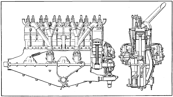
Fig. 246.—Part Sectional Side View and Sectional End View of Benz 160 Horse-Power Aviation Engine.
Some interesting details of the 160 horse-power Benz motor, which is shown at Fig. 246, are reproduced from the “Aerial Age Weekly,” and show how carefully the design has been considered.
Maximum horse-power, 167.5 B. H. P.
Speed at maximum horse-power, 1,500 R. P. M.
Piston speed at maximum horse-power, 1,770 ft. per minute.
Normal horse-power, 160 B. H. P.
Speed at normal horse-power, 1,400 R. P. M.
Piston speed at normal horse-power, 1,656 ft. per minute.
Brake mean pressure at maximum horse-power, 101.2 pound per square inch.
Brake mean pressure at normal horse-power, 103.4 pound per square inch.
Specific power cubic inch swept volume per B. H. P., 5.46 cubic inch; 160 B. H. P.
Weight of piston, complete with gudgeon pin, rings, etc., 5.0 pound.
Weight of connecting rod, complete with bearings, 4.99 pound; 1.8 pound reciprocating.
Weight of reciprocating parts per cylinder, 6.8 pound.
Weight of reciprocating parts per square inch of piston area, 0.33 pound.
Outside diameter of inlet valve, 68 mm.; 2.68 inches.
Diameter of inlet valve port (d), 61.5 mm.; 2.42 inches.
Maximum lift of inlet valve (h), 11 mm.; 0.443 inch.
Area of inlet valve opening (π d h), 21.25 square cm.; 3.29 square inches.
Inlet valve opens, degrees on crank, top dead center.
Inlet valve closes, degrees on crank, 60° late; 35 mm. late.
Outside diameter of exhaust valve, 68 mm.; 2.68 inches.
Diameter of exhaust valve port (d), 61.5 mm.; 2.42 inches.
Maximum lift of exhaust valve (h) 11 mm.; 0.433 inch.
Area of exhaust valve opening (π d h), 21.25 square cm.; 3.29 square inches.
Exhaust valve opens, degrees on crank, 60° early; 35 mm. early.
Exhaust valve closes, degrees on crank, 161⁄2° late; 5 mm. late.
Length of connecting rod between centers, 314 mm.; 12.36 inches.
Ratio connecting rod to crank throw, 3.49:1.
Diameter of crank-shaft, 55 mm. outside, 2.165 inches; 28 mm. inside, 1.102 inches.
Diameter of crank-pin, 55 mm. outside, 2.165 inches; 28 mm. inside, 1.102 inches.
Diameter of gudgeon pin, 30 mm. outside, 1.181 inches; 19 mm. inside, 0.708 inch.
Diameter of cam-shaft, 26 mm. outside, 1.023 inches; 18 mm. inside, 0.708 inch.
Number of crank-shaft bearings, 7.
Projected area of crank-pin bearings, 36.85 square cm.; 5.72 square inches.
Projected area of gudgeon pin bearings, 22.20 square cm.; 3.44 square inches.
Firing sequence, 1, 5, 3, 6, 2, 4.
Type of magnetos, ZH6 Bosch.
Direction of rotation of magneto from driving end, one clock, one anti-clock.
Magneto timing, full advance, 30° early (16 mm. early).
Type of carburetors (2) Benz design.
Fuel consumption per hour, normal horse-power, 0.57 pint.
Normal speed of propeller, engine speed, 1,400 R. P. M.
AUSTRO-DAIMLER ENGINE
One of the first very successful European flying engines which was developed in Europe is the Austro-Daimler, which is shown in end section in a preceding chapter. The first of these motors had four-cylinders, 120 by 140 millimeters, bore and stroke, with cast iron cylinders, overhead valves operated by means of a single rocker arm, controlled by two cams and the valves were closed by a single leaf spring which oscillates with the rocker arm. The cylinders are cast singly and have either copper or steel jackets applied to them. The four-cylinder design was afterwards expanded to the six-cylinder design and still later a six-cylinder motor of 130 by 175 millimeters was developed. This motor uses an offset crank-shaft, as does the Benz motor, and the effect of offset has been discussed earlier on in this treatise. The Benz motor also uses an offset cam-shaft which improves the valve operation and changes the valve lift diagram. The lubrication also is different than any other aviation motor, since individual high pressure metering pumps are used to deliver fresh oil only to the bearings and cylinders, as was the custom in automobile practice some ten years ago.
SUNBEAM AVIATION ENGINES
These very successful engines have been developed by Louis Coatalen. At the opening of the war the largest sized Coatalen motor was 225 horse-power and was of the L-head type having a single cam-shaft for operating valves and was an evolution from the twelve-cylinder racing car which the Sunbeam Company had previously built. Since 1914 the Sunbeam Company have produced engines of six-, eight-, twelve- and eighteen-cylinders from 150 to 500 horse-power with both iron and aluminum cylinders. For the last two years all the motors have had overhead cam-shafts with a separate shaft for operating the intake and exhaust valves. Cam-shafts are connected through to the crank-shaft by means of a train of spur gears, all of which are mounted on two double row ball bearings. In the twin six, 350 horse-power engine, operating at 2100 R. P. M., requires about 4 horse-power to operate the cam-shafts. This motor gives 362 horsepower at 2100 revolutions and has a fuel consumption of 51⁄100 of a pint per brake horse-power hour. The cylinders are 110 by 160 millimeters. The same design has been expanded into an eighteen-cylinder which gives 525 horsepower at 2100 turns. There has also been developed a very successful eight-cylinder motor rated at 2220 horsepower which has a bore and stroke of 120 by 130 millimeters, weight 450 pounds. This motor is an aluminum block construction with steel sleeves inserted. Three valves are operated, one for the inlet and two for the exhaust. One cam-shaft operates the three valves.
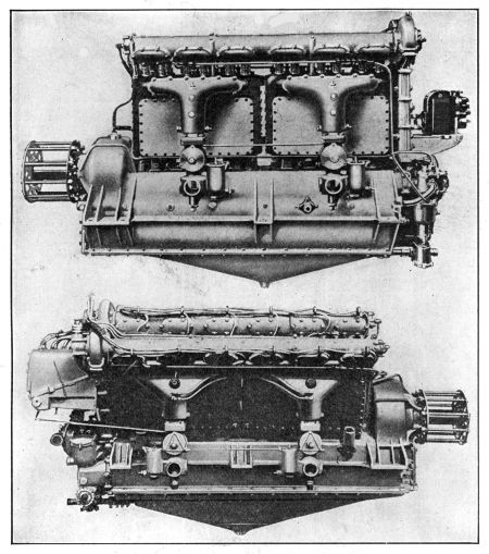
Fig. 247.—At Top, the Sunbeam Overhead Valve 170 Horse-Power Six-Cylinder Engine. Below, Side View of Sunbeam 350 Horse-Power Twelve-Cylinder Vee Engine.
The modern Sunbeam engines operate with a mean effective pressure of 135 pounds with a compression ratio of 6 to 1 sea level. The connecting rods are of the articulated type as in the Renault motor and are very short. The weight of these motors turns out at 2.6 pounds per brake horse-power, and they are able to go through a 100 hour test without any trouble of any kind. The lubricating system comprises a dry base and oil pump for drawing the oil off from the base, whence it is delivered to the filter and cooling system. It then is pumped by a separate high pressure gear pump through the entire motor. In these larger European motors, castor-oil is used largely for lubrication. It is said that without the use of castor-oil it is impossible to hold full power for five hours. Coatalen favors aluminum cylinders rather than cast iron. The series of views in Figs. 247 to 250 inclusive, illustrates the vertical, narrow type of engine; the V-form; and the broad arrow type wherein three rows, each of six-cylinders, are set on a common crank-case. In this water-cooled series the gasoline and oil consumption are notably low, as is the weight per horse-power.
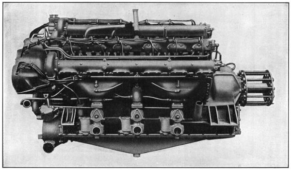
Fig. 248.—Side View of Eighteen-Cylinder Sunbeam Coatalen Aircraft Engine Rated at 475 B.H.P.
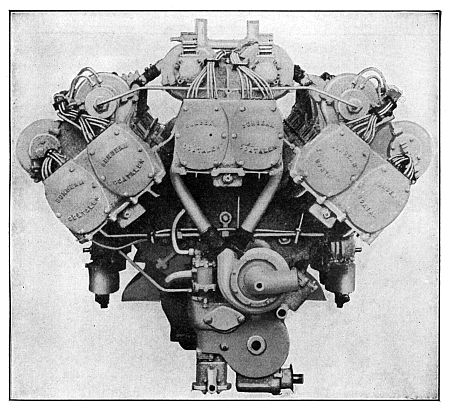
Fig. 249.—Sunbeam Eighteen-Cylinder Motor, Viewed from Pump and Magneto End.
In the eighteen-cylinder overhead valve Sunbeam-Coatalen aircraft engine of 475 brake horse-power, there are no fewer than half a dozen magnetos. Each magneto is inclosed. Two sparks are furnished to each cylinder from independent magnetos. On this engine there are also no fewer than six carburetors. Shortness of crank-shaft, and therefore of engine length, and absence of vibration are achieved by the linking of the connecting-rods. Those concerned with three-cylinders in the broad arrow formation work on one crank-pin, the outer rods being linked to the central master one. In consequence of this arrangement, the piston travel in the case of the central row of cylinders is 160 mm., while the stroke of the pistons of the cylinders set on either side is in each case 168 mm. Inasmuch as each set of six-cylinders is completely balanced in itself, this difference in stroke does not affect the balance of the engine as a whole. The duplicate ignition scheme also applies to the twelve-cylinder 350 brake horse-power Sunbeam-Coatalen overhead valve aircraft engine type. It is distinguishable, incidentally, by the passage formed through the center of each induction pipe for the sparking plug in the center cylinder of each block of three. In this, as in the eighteen-cylinder and the six-cylinder types, there are two cam-shafts for each set of cylinders. These cam-shafts are lubricated by low pressure and are operated through a train of inclosed spur wheels at the magneto end of the machine. The six-cylinder, 170 brake horse-power vertical type employs the same general principles, including the detail that each carburetor serves gas to a group of three-cylinders only. It will be observed that this engine presents notably little head resistance, being suitable for multi-engined aircraft.
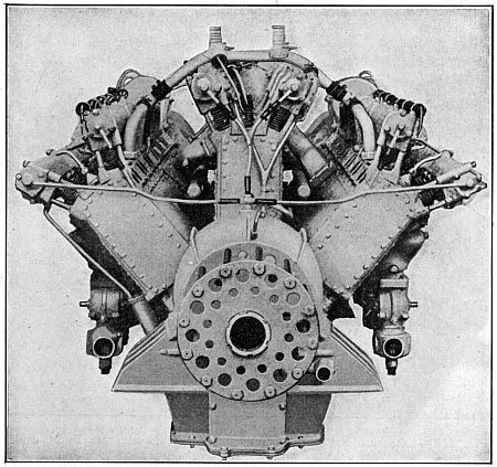
Fig. 250.—Propeller End of Sunbeam Eighteen-Cylinder 475 B.H.P. Aviation Engine.
INDICATING METERS FOR AUXILIARY SYSTEMS
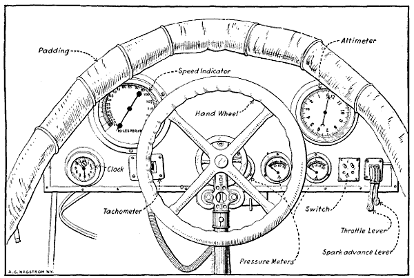
Fig. 251.—View of Airplane Cowl Board, Showing the Various Navigating and Indicating Instruments to Aid the Aviator in Flight.
The proper functioning of the power plant and the various groups comprising it may be readily ascertained at any time by the pilot because various indicating meters and pressure gauges are provided which are located on a dash or cowl board in front of the aviator, as shown at Fig. 251. The speed indicator corresponds to the speedometer of an automobile and gives an indication of the speed the airplane is making, which taken in conjunction with the clock will make it possible to determine the distance covered at a flight. The altimeter, which is an aneroid barometer, outlines with fair accuracy the height above the ground at which a plane is flying. These instruments are furnished to enable the aviator to navigate the airplane when in the air, and if the machine is to be used for cross-country flying, they may be supplemented by a compass and a drift set. It will be evident that these are purely navigating instruments and only indicate the motor condition in an indirect manner. The best way of keeping track of the motor action is to watch the tachometer or revolution counter which is driven from the engine by a flexible shaft. This indicates directly the number of revolutions the engine is making per minute and, of course, any slowing up of the engine in normal flights indicates that something is not functioning as it should. The tachometer operates on the same principle as the speed indicating device or speedometer used in automobiles except that the dial is calibrated to show revolutions per minute instead of miles per hour. At the extreme right of the dash at Fig. 251 the spark advance and throttle control levers are placed. These, of course, regulate the motor speed just as they do in an automobile. Next to the engine speed regulating levers is placed a push button cut-out switch to cut out the ignition and stop the motor. Three pressure gauges are placed in a line. The one at the extreme right indicates the pressure of air on the fuel when a pressure feed system is used. The middle one shows oil pressure, while that nearest the center of the dash board is employed to show the air pressure available in the air starting system. It will be evident that the character of the indicating instruments will vary with the design of the airplane. If it was provided with an electrical starter instead of an air system electrical indicating instruments would have to be provided.
COMPRESSED AIR-STARTING SYSTEMS
Two forms of air-starting systems are in general use, one in which the crank-shaft is turned by means of an air motor, the other class where compressed air is admitted to the cylinders proper and the motor turned over because of the air pressure acting on the engine pistons. A system known as the “Never-Miss” utilizes a small double-cylinder air pump is driven from the engine by means of suitable gearing and supplies air to a substantial container located at some convenient point in the fuselage. The air is piped from the container to a dash-control valve and from this member to a peculiar form of air motor mounted near the crank-shaft. The air motor consists of a piston to which a rack is fastened which engages a gear mounted on the crank shaft provided with some form of ratchet clutch to permit it to revolve only in one direction, and then only when the gear is turning faster than the engine crank-shaft.
The method of operation is extremely simple, the dash-control valve admitting air from the supply tank to the top of the pump cylinder. When in the position shown in cut the air pressure will force the piston and rack down and set the engine in motion. A variety of air motors are used and in some the pump and motor may be the same device, means being provided to change the pump to an air motor when the engine is to be turned over.
The “Christensen” air starting system is shown at Figs. 252 and 253. An air pump is driven by the engine, and this supplies air to an air reservoir or container attached to the fuselage. This container communicates with the top of an air distributor when a suitable control valve is open. An air pressure gauge is provided to enable one to ascertain the air pressure available. The top of each cylinder is provided with a check valve, through which air can flow only in one direction, i.e., from the tank to the interior of the cylinder. Under explosive pressure these check valves close. The function of the distributor is practically the same as that of an ignition timer, its purpose being to distribute the air to the cylinders of the engine only in the proper firing order. All the while that the engine is running and the car is in motion the air pump is functioning, unless thrown out of action by an easily manipulated automatic control. When it is desired to start the engine a starting valve is opened which permits the air to flow to the top of the distributor, and then through a pipe to the check valve on top of the cylinder about to explode. As the air is going through under considerable pressure it will move the piston down just as the explosion would, and start the engine rotating. The inside of the distributor rotates and directs a charge of air to the cylinder next to fire. In this way the engine is given a number of revolutions, and finally a charge of gas will be ignited and the engine start off on its cycle of operation. To make starting positive and easier some gasoline is injected in with the air so an inflammable mixture is present in the cylinders instead of air only. This ignites easily and the engine starts off sooner than would otherwise be the case. The air pressure required varies from 125 to 250 pounds per square inch, depending upon the size and type of the engine to be set in motion.
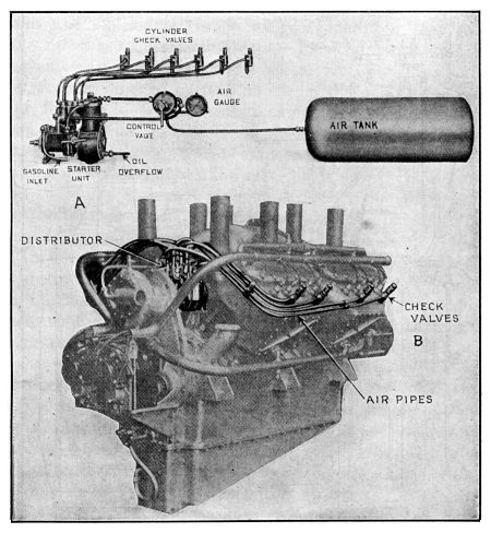
Fig. 252.—Parts of Christensen Air Starting System Shown at A, and Application of Piping and Check Valves to Cylinders of Thomas-Morse Aeromotor Outlined at B.
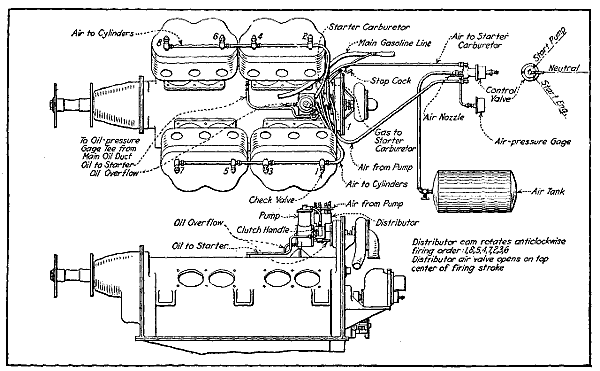
Fig. 253.—Diagrams Showing Installation of Air Starting System on Thomas-Morse Aviation Motor.
ELECTRIC STARTING SYSTEMS
Starters utilizing electric motors to turn over the engine have been recently developed, and when properly made and maintained in an efficient condition they answer all the requirements of an ideal starting device. The capacity is very high, as the motor may draw current from a storage battery and keep the engine turning over for considerable time on a charge. The objection against their use is that it requires considerable complicated and costly apparatus which is difficult to understand and which requires the services of an expert electrician to repair should it get out of order, though if battery ignition is used the generator takes the place of the usual ignition magneto.
In the Delco system the electric current is generated by a combined motor-generator permanently geared to the engine. When the motor is running it turns the armature and the motor generator is acting as a dynamo, only supplying current to a storage battery. On account of the varying speeds of the generator, which are due to the fluctuation in engine speed, some form of automatic switch which will disconnect the generator from the battery at such times that the motor speed is not sufficiently high to generate a current stronger than that delivered by the battery is needed. These automatic switches are the only delicate part of the entire apparatus, and while they require very delicate adjustment they seem to perform very satisfactorily in practice.
When it is desired to start the engine an electrical connection is established between the storage battery and the motor-generator unit, and this acts as a motor and turns the engine over by suitable gearing which engages the gear teeth cut into a special gear or disc attached to the engine crank-shaft. When the motor-generator furnishes current for ignition as well as for starting the motor, the fact that the current can be used for this work as well as starting justifies to a certain extent the rather complicated mechanism which forms a complete starting and ignition system, and which may also be used for lighting if necessary in night flying.
An electric generator and motor do not complete a self-starting system, because some reservoir or container for electric current must be provided. The current from the generator is usually stored in a storage battery from which it can be made to return to the motor or to the same armature that produced it. The fundamental units of a self-starting system, therefore, are a generator to produce the electricity, a storage battery to serve as a reservoir, and an electric motor to rotate the motor crank-shaft. Generators are usually driven by enclosed gearing, though silent chains are used where the center distance between the motor shaft and generator shaft is too great for the gears. An electric starter may be directly connected to the gasoline engine, as is the case where the combined motor-generator replaces the fly-wheel in an automobile engine. The motor may also drive the engine by means of a silent chain or by direct gear reduction.
Every electric starter must use a switch of some kind for starting purposes and most systems include an output regulator and a reverse current cut-out. The output regulator is a simple device that regulates the strength of the generator current that is supplied the storage battery. A reverse current cut-out is a form of check valve that prevents the storage battery from discharging through the generator. Brief mention is made of electric starting because such systems will undoubtedly be incorporated in some future airplane designs. Battery ignition is already being experimented with.
BATTERY IGNITION SYSTEM PARTS
A battery ignition system in its simplest form consists of a current producer, usually a set of dry cells or a storage battery, an induction coil to transform the low tension current to one having sufficient strength to jump the air gap at the spark-plug, an igniter member placed in the combustion chamber and a timer or mechanical switch operated by the engine so that the circuit will be closed only when it is desired to have a spark take place in the cylinders. Battery ignition systems may be of two forms, those in which the battery current is stepped up or intensified to enable it to jump an air gap between the points of the spark plug, these being called “high tension” systems and the low tension form (never used on airplane motors) in which the battery current is not intensified to a great degree and a spark produced in the cylinder by the action of a mechanical circuit breaker in the combustion chamber. The low tension system is the simplest electrically but the more complex mechanically. The high tension system has the fewest moving parts but numerous electrical devices. At the present time all airplane engines use high tension ignition systems, the magneto being the most popular at the present time. The current distribution and timing devices used with modern battery systems are practically the same as similar parts of a magneto.