CHAP. XXI. ON BALANCES AND PENDULUMS.
Reading edition
(335.) The preceding chapters have been confined almost wholly to the consideration of the laws of mechanics, without entering into a particular description of the machinery and instruments dependant upon those laws. Such descriptions would have interfered too much with the regular progress of the subject, and it therefore appeared preferable to devote a chapter exclusively to this portion of the work.
Perhaps there are no ideas which man receives through the medium of sense which may not be referred ultimately to matter and motion. In proportion, therefore, as he becomes acquainted with the properties of the one and the laws of the other, his knowledge is extended, his comforts are multiplied; he is enabled to bend the powers of nature to his will, and to construct machinery which effects with ease that which the united labour of thousands would in vain be exerted to accomplish.
Of the properties of matter, one of the most important is its weight, and the element which mingles inseparably with the laws of motion is time.
In the present chapter it is our intention to describe such instruments as are usually employed for determining the weight of bodies. To attempt a description of the various machines which are used for the measurement of time, would lead us into too wide a field for the present occasion, and we shall, therefore, confine ourselves to an account of the methods which have been practised to perfect, to perfect that instrument which affords the most correct means of measuring time, the pendulum.
The instrument by which we are enabled to determine, with greater accuracy than by any other means, the relative weight of a body, compared with the weight of another body assumed as a standard, is the balance.
H. Adlard, sc.
London, Pubd. by Longman & Co.
Of the Balance.
The balance may be described as consisting of an inflexible rod or lever, called the beam, furnished with three axes; one, the fulcrum or centre of motion situated in the middle, upon which the beam turns, and the other two near the extremities, and at equal distances from the middle. These last are called the points of support, and serve to sustain the pans or scales.
The points of support and the fulcrum are in the same right line, and the centre of gravity of the whole should be a little below the fulcrum when the position of the beam is horizontal.
The arms of the lever being equal, it follows that if equal weights be put into the scales no effect will be produced on the position of the balance, and the beam will remain horizontal.
If a small addition be made to the weight in one of the scales, the horizontality of the beam will be disturbed; and after oscillating for some time, it will, on attaining a state of rest, form an angle with the horizon, the extent of which is a measure of the delicacy or sensibility of the balance.
As the sensibility of a balance is of the utmost importance in nice scientific enquiries, we shall enter somewhat at large into a consideration of the circumstances by which this property is influenced.
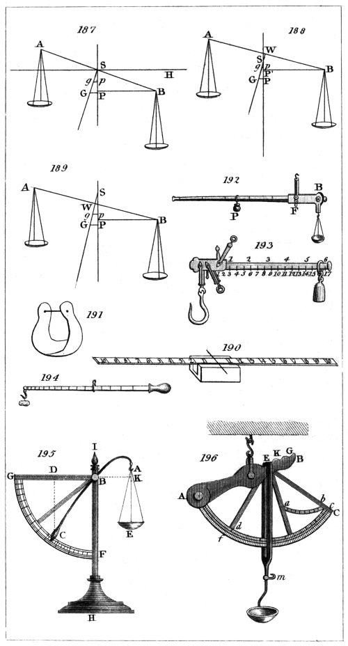
In fig. 187. let A B represent the beam drawn from the horizontal position by a very small weight placed in the scale suspended from the point of support B; then the force tending to draw the beam from the horizontal position may be expressed by P B, multiplied by such very small weight acting upon the point B.
Let the centre of gravity of the whole be at G; then the force acting against the former will be G P multiplied into the weight of the beam and scales, and when these forces are equal, the beam will rest in an inclined position. Hence we may perceive that as the centre of gravity is nearer to or further from the fulcrum S, (every thing else remaining the same) the sensibility of the balance will be increased or diminished.
For, suppose the centre of gravity were removed to g, then to produce an opposing force equal to that acting upon the extremity of the beam, the distance g p from the perpendicular line must be increased until it becomes nearly equal to G P; but for this purpose the end of the beam B must descend, which will increase the angle H S B.
As all weights placed in the scales are referred to the line joining the points of support, and as this line is above the centre of gravity of the beam when not loaded, such weights will raise the centre of gravity; but it will be seen that the sensibility of the balance, as far as it depends upon this cause, will remain unaltered.
For, calling the distance S G unity, the distance of the centre of gravity from the point S (to which the weight which has been added is referred) will be expressed by the reciprocal of the weight of the beam so increased; that is, if the weight of the beam be doubled by weights placed in the scales, S g will be one half of S G; and if the weight of the beam be in like manner trebled, S g will be one third of S G, and so on. And as G P varies as S G, g p will be inversely proportionate to the increased weight of the beam, and consequently, the product obtained by multiplying g p by the weight of the beam and its load will be a constant quantity, and the sensibility of the balance, as before stated, will suffer no alteration.
We will now suppose that the fulcrum S, fig. 188., is situated below the line joining the points of support, and that the centre of gravity of the beam when not loaded is at G. Also that when a very small weight is placed in the scale suspended from the point B, the beam is drawn from its horizontal position, the deviation being a measure of the sensibility of the balance. Then, as before stated, G P multiplied by the weight of the beam will be equal to P′ B multiplied by the very small additional weight acting on the point B.
Now if we place equal weights in both scales, such additional weights will be referred to the point W, and the resulting distance of the centre of gravity from the point W, calling W G unity, will be expressed as before by the reciprocal of the increased weight of the loaded beam. But G P will decrease in a greater proportion than W G: thus, supposing the weight of the beam to be doubled, W g would be one half of W G; but g p, as will be evident on an inspection of the figure, will be less than half of G P; and the same small weight which was before applied to the point B, if now added, would depress the point B, until the distance g p became such as that, when multiplied by the weight of the whole, the product would be as before equal to P′ B, multiplied by the before mentioned very small added weight. The sensibility of the balance, therefore, in this case would be increased.
If the beam be sufficiently loaded, the centre of gravity will at length be raised to the fulcrum S, and the beam will rest indifferently in any position. If more weight be then added, the centre of gravity will be raised above the fulcrum, and the beam will turn over.
Lastly, if the fulcrum S, fig. 189., is above the line joining the two points of support, as any additional weights placed in the scales will be referred to the point W, in the line joining A and B, if the weight of the beam be doubled by such added weights, and the centre of gravity be consequently raised to g, W g will become equal to half of W G. But g p, being greater than one half of G P, the end of the beam B will rise until g p becomes such as to be equal, when multiplied by the whole increased weight of the beam, to P B, multiplied by the small weight, which we suppose to have been placed as in the preceding examples, in the scale.
From what has been said it will be seen that there are three positions of the fulcrum which influence the sensibility of the balance: first, when the fulcrum and the points of support are in a right line, when the sensibility of the balance will remain the same, though the weight with which the beam is loaded should be varied: secondly, when the fulcrum is below the line joining the two points of support, in which case the sensibility of the balance will be increased by additional weights, until at length the centre of gravity is raised above the fulcrum, when the beam will turn over; and, thirdly, when the fulcrum is above the line joining the two points of support, in which case the sensibility of the balance will be diminished as the weight with which the beam is loaded is increased.
The sensibility of a balance, as here defined, is the angular deviation of the beam occasioned by placing an additional constant small weight in one of the scales; but it is frequently expressed by the proportion which such small additional weight bears to the weight of the beam and its load, and sometimes to the weight the value of which is to be determined.
This proportion, however, will evidently vary with different weights, except in the case where the centre of gravity of the beam is in the line joining the points supporting the scales, the fulcrum being above this line, and it is therefore necessary, in every other case, when speaking of the sensibility of the balance, to designate the weight with which it is loaded: thus, if a balance has a troy pound in each scale, and the horizontality of the beam varies a certain small quantity, just perceptible on the addition of one hundredth of a grain, we say that the balance is sensible to 1/1152000 part of its load with a pound in each scale, or that it will determine the weight of a troy pound within 1/576000 part of the whole.
The nearer the centre of gravity of a balance is to its fulcrum the slower will be the oscillations of the beam. The number of oscillations, therefore, made by the beam in a given time (a minute for example), affords the most accurate method of judging of the sensibility of the balance, which will be the greater as the oscillations are fewer.
Balances of the most perfect kind, and of such only it is our present object to treat, are usually furnished with adjustments, by means of which the length of the arms, or the distances of the fulcrum from the points of support, may be equalised, and the fulcrum and the two points of support be placed in a right line; but these adjustments, as will hereafter be seen, are not absolutely necessary.
The beam is variously constructed, according to the purposes to which the balance is to be applied. Sometimes it is made of a rod of solid steel; sometimes of two hollow cones joined at their bases; and, in some balances, the beam is a frame in the form of a rhombus: the principal object in all, however, is to combine strength and inflexibility with lightness.
A balance of the best kind, made by Troughton, is so contrived as to be contained, when not in use, in a drawer below the case; and when in use, it is protected from any disturbance from currents of air, by being enclosed in the case above the drawer, the back and front of which are of plate glass. There are doors in the sides, through which the scale-pans are loaded, and there is a door at the top through which the beam may be taken out.
A strong brass pillar, in the centre of the box, supports a square piece, on the front and back of which rise two arches, nearly semicircular, on which are fixed two horizontal planes of agate, intended to support the fulcrum. Within the pillar is a cylindrical tube, which slides up and down by means of a handle on the outside of the case. To the top of this interior tube is fixed an arch, the terminations of which pass beneath and outside of the two arches before described. These terminations are formed into Y s, destined to receive the ends of the fulcrum, which are made cylindrical for this purpose, when the interior tube is elevated in order to relieve the axis when the balance is not in use. On depressing the interior tube, the Y s quit the axis, and leave it in its proper position on the agate planes. The beam is about eighteen inches long, and is formed of two hollow cones of brass, joined at their bases. The thickness of the brass does not exceed 0·02 of an inch, but by means of circular rings driven into the cones at intervals they are rendered almost inflexible. Across the middle of the beam passes a cylinder of steel, the lower side of which is formed into an edge, having an angle of about thirty degrees, which, being hardened and well polished, constitutes the fulcrum, and rests upon the agate planes for the length of about 0·05 of an inch.
Each point of suspension is formed of an axis having two sharp concave edges, upon which rest at right angles two other sharp concave edges formed in the spur-shaped piece to which the strings carrying the scale-pan are attached. The two points are adjustable, the one horizontally, for the purpose of equalising the arms of the beam, and the other vertically, for bringing the points of suspension and the fulcrum into a right line.
Such is the form of Troughton’s balance: we shall now give the description of a balance as constructed by Mr. Robinson of Devonshire Street, Portland Place:—
The beam of this balance is only ten inches long. It is a frame of bell-metal in the form of a rhombus. The fulcrum is an equilateral triangular prism of steel one inch in length; but the edge on which the beam vibrates is formed to an angle of 120°, in order to prevent any injury from the weight with which it may be loaded. The chief peculiarity in this balance consists in the knife-edge which forms the fulcrum bearing upon an agate plane throughout its whole length, whereas we have seen in the balance before described that the whole weight is supported by portions only of the knife-edge, amounting together to one tenth of an inch. The supports for the scales are knife-edges each six tenths of an inch long. These are each furnished with two pressing screws, by means of which they may be made parallel to the central knife-edge.
Each end of the beam is sprung obliquely upwards and towards the middle, so as to form a spring through which a pushing screw passes, which serves to vary the distance of the point of support from the fulcrum, and, at the same time, by its oblique action to raise or depress it, so as to furnish a means of bringing the points of support and the fulcrum into a right line.
A piece of wire, four inches long, on which a screw is cut, proceeds from the middle of the beam downwards. This is pointed to serve as an index, and a small brass ball moves on the screw, by changing the situation of which the place of the centre of gravity may be varied at pleasure.
The fulcrum, as before remarked, rests upon an agate plane throughout its whole length, and the scale-pans are attached to planes of agate which rest upon the knife-edges forming the points of support. This method of supporting the scale-pans, we have reason to believe, is due to Mr. Cavendish. Upon the lower half of the pillar to which the agate plane is fixed, a tube slides up and down by means of a lever which passes to the outside of the case. From the top of this tube arms proceed obliquely towards the ends of the balance, serving to support a horizontal piece, carrying at each extremity two sets of Y s, one a little above the other. The upper Y s are destined to receive the agate planes to which the scale-pans are attached, and thus to relieve the knife-edges from their pressure; the lower to receive the knife-edges which, form the points of support, consequently these latter Y s, when in action, sustain the whole beam.
When the lever is freed from a notch in which it is lodged, a spring is allowed to act upon the tube we have mentioned, and to elevate it. The upper Y s first meet the agate planes carrying the scale-pans and free them from the knife-edges. The lower Y s then come into action and raise the whole beam, elevating the central knife-edge above the agate plane. This is the usual state of the balance when not in use: when it is to be brought into action, the reverse of what we have described takes place. On pressing down the lever, the central knife-edge first meets the agate plane, and afterwards the two agate planes carrying the scale-pans are deposited upon their supporting knife-edges.
A balance of this construction was employed by the writer of this article in adjusting the national standard pound. With a pound troy in each scale, the addition of one hundredth of a grain caused the index to vary one division, equal to one tenth of an inch, and Mr. Robinson adjusts these balances so that with one thousand grains in each scale, the index varies perceptibly on the addition of one thousandth of a grain, or of one-millionth part of the weight to be determined.
It may not be uninteresting to subjoin, from the Philosophical Transactions for 1826, the description of a balance perhaps the most sensible that has yet been made, constructed for verifying the national standard bushel. The author says,—
“The weight of the bushel measure, together with the 80 lbs. of water it should contain, was about 250 lbs.; and as I could find no balance capable of determining so large a weight with sufficient accuracy, I was under the necessity of constructing one for this express purpose.
“I first tried cast iron; but though the beam was made as light as was consistent with the requisite degree of strength, the inertia of such a mass appeared to be so considerable, that much time must have been lost before the balance would have answered to the small differences I wished to ascertain. Lightness was a property essentially necessary, and bulk was very desirable, in order to preclude such errors as might arise from the beam being partially affected by sudden alterations of temperature. I therefore determined to employ wood, a material in which the requisites I sought were combined. The beam was made of a plank of mahogany, about 7O inches long, 22 inches wide, and 21/4 thick, tapering from the middle to the extremities. An opening was cut in the centre, and strong blocks screwed to each side of the plank, to form a bearing for the back of a knife-edge which passed through the centre. Blocks were also screwed to each side at the extremities of the beam on which rested the backs of the knife-edges for supporting the pans. The opening in the centre was made sufficiently large to admit the support hereafter to be described, upon which the knife-edge rested.
“In all beams which I have seen, with the exception of those made by Mr. Robinson, the whole weight is sustained by short portions at the extremities of the knife-edge; and the weight being thus thrown upon a few points, the knife-edge becomes more liable to change its figure and to suffer injury.
“To remedy this defect, the central knife-edge of the beam I am describing was made 6 inches, and the two others 5 inches long. They were triangular prisms with equal sides of three fourths of an inch, very carefully finished, and the edges ultimately formed to an angle of 120°.
“Each knife-edge was screwed to a thick plate of brass, the surfaces in contact having been previously ground together; and these plates were screwed to the beam, the knife-edges being placed in the same plane, and as nearly equidistant and parallel to each other as could be done by construction.
“The support upon which the central knife-edge rested throughout its whole length was formed of a plate of polished hard steel, screwed to a block of cast iron. This block was passed through the opening before mentioned in the centre of the beam, and properly attached to a frame of cast iron.
“The stirrups to which the scales were hooked rested upon plates of polished steel to which they were attached, and the under surfaces of which were formed by careful grinding into cylindrical segments. These were in contact with the knife-edges their whole length, and were known to be in their proper position by the correspondence of their extremities with those of the knife-edges. A well imagined contrivance was applied by Mr. Bate for raising the beam when loaded, in order to prevent unnecessary wear of the knife-edge, and for the purpose of adjusting the place of the centre of gravity, when the beam was loaded with the weight required to be determined, a screw carrying a movable ball projected vertically from the middle of die beam.
“The performance of this balance fully equalled my expectations. With two hundred and fifty pounds in each scale, the addition of a single grain occasioned an immediate variation in the index of one twentieth of an inch, the radius being fifty inches.”
From the preceding account it appears that this balance is sensible to 1/1750000 part of the weight which was to be determined.
We shall now describe the method to be pursued in adjusting a balance.
1. To bring the points of suspension and the fulcrum into a right line.
Make the vibrations of the balance very slow by moving the weight which influences the centre of gravity, and bring the beam into a horizontal position, by means of small bits of paper thrown into the scales. Then load the scales with nearly the greatest weight the beam is fitted to carry. If the vibrations are performed in the same time as before, no further adjustment is necessary; but if the beam vibrates quicker, or if it oversets, cause it to vibrate in the same time as at first, by moving the adjusting weight, and note the distance through which the weight has passed. Move the weight then in the contrary direction through double this distance, and then produce the former slow motion by means of the screw acting vertically on the point of support. Repeat this operation until the adjustment is perfect.
2. To make the arms of the beam of an equal length.
Put weights in the scales as before; bring the beam as nearly as possible to a horizontal position, and note the division at which the index stands; unhook the scales, and transfer them with their weights to the other ends of the beam, when, if the index points to the same division, the arms are of an equal length; but if not, bring the index to the division which had been noted, by placing small weights in one or the other scale. Take away half these weights, and bring the index again to the observed division by the adjusting screw, which acts horizontally on the point of support. If the scale-pans are known to be of the same weight, it will not be necessary to change the scales, but merely to transfer the weights from one scale-pan to the other.
Of the Use of the Balance.
Though we have described the method of adjusting the balance, these adjustments, as we have before remarked, may be dispensed with. Indeed, in all delicate scientific operations, it is advisable never to rely upon adjustments, which, after every care has been employed in effecting them, can only be considered as approximations to the truth. We shall, therefore, now describe the best method of ascertaining the weight of a body, and which does not depend on the accuracy of these adjustments.
Having levelled the case which contains the balance, and thrown the beam out of action, place a weight in each scale-pan nearly equal to the weight which is to be determined. Lower the beam very gently till it is in action, and by means of the adjustment for raising or lowering the centre of gravity, cause the beam to vibrate very slowly. Remove these weights, and place the substance, the weight of which is to be determined in one of the scale-pans; carefully counterpoise it by means of any convenient substances put into the other scale-pan, and observe the division at which the index stands; remove the body, the weight of which is to be ascertained, and substitute standard weights for it so as to bring the index to the same division as before. These weights will be equal to the weight of the body.
If it be required to compare two weights together which are intended to be equal, and to ascertain their difference, if any, the method of proceeding will be nearly the same. The standard weight is to be carefully counterpoised, and the division at which the index stands, noted. And now it will be convenient to add in either of the scales some small weight, such as one or two hundredths of a grain, and mark the number of divisions passed over in consequence by the index, by which the value of one division of the scale will be known. This should be repeated a few times, and the mean taken for greater certainty.
Having noted the division at which the index rests, the standard weight is to be removed, and the weight which is to be compared with it substituted for it. The index is then again to be noted, and the difference between this and the former indication will give the difference between the weights in parts of a grain.
If the balance is adjusted so as to be very sensible, it will be long before it comes to a state of rest. It may, therefore, sometimes be advisable to take the mean of the extent of the vibrations of the index as the point where it would rest, and this may be repeated several times for greater accuracy. It must, however, be remembered, that it is not safe to do this when the extent of the vibrations is beyond one or two divisions of the scale; but with this limitation it is, perhaps, as good a method as can be pursued.
Many precautions are necessary to ensure a satisfactory result. The weights should never be touched by the hand; for not only would this oxydate the weight, but by raising its temperature it would appear lighter, when placed in the scale-pan, than it should do, in consequence of the ascent of the heated air. For the larger weights a wooden fork or tongs, according to the form of the weight, should be employed; and for the smaller, a pair of forceps made of copper will be found the most convenient. This metal possessing sufficient elasticity to open the forceps on their being released from pressure, and yet not opposing a resistance sufficient to interfere with that delicacy of touch which is desirable in such operations.
Of Weights.
It must be obvious, that the excellence of the balance would be of little use, unless the weights employed were equally to be depended upon. The weights may either be accurately adjusted, or the difference between each weight and the standard may be determined, and, consequently, its true value ascertained. It has been already shown how the latter may be effected, in the instructions which have been given for comparing two weights together; and we shall now show the readiest mode of adjusting weights to an exact equality with a given standard.
The material of the weight may be either brass or platina, and its form may be cylindrical: the diameter being nearly twice the height. A small spherical knob is screwed into the centre, a space being left under the screw to receive the portions of fine wire used in the adjustment. It will be convenient to form a cavity in the bottom of each weight to receive the knob of the weight upon which it may be placed.
Each weight is now to be compared with the standard, and should it be too heavy, it is to be reduced till it becomes in a very small degree too light, when the amount of the deficiency is to be carefully determined.
Some very fine silver wire is now to be taken, and the weight of three or four feet of it ascertained. From this it will be known what length of the wire is equal to the error of the weight to be adjusted; and this length being cut off is to be enclosed under the screw. To guard against any possible error, it will be advisable before the screw is firmly fixed in its place, again to compare the weight with the standard.
The most approved method of making weights expressing the decimal parts of a grain, is to determine, as before, with great care, the weight of a certain length of fine wire, and then to cut off such portions as are equal to the weights required.
Before we conclude this article we shall give a description, from the Annals of Philosophy for 1825, of “a very sensible balance,” used by the late Dr. Black:—
“A thin piece of fir wood, not thicker than a shilling, and a foot long, three tenths of an inch broad in the middle, and one tenth and a half at each end, is divided by transverse lines into twenty parts; that is, ten parts on each side of the middle. These are the principal divisions, and each of them is subdivided into halves and quarters. Across the middle is fixed one of the smallest needles I could procure, to serve as an axis, and it is fixed in its place by means of a little sealing wax. The numeration of the divisions is from the middle to each end of the beam. The fulcrum is a bit of plate brass, the middle of which lies flat on my table when I use the balance, and the two ends are bent up to a right angle so as to stand upright. These two ends are ground at the same time on a flat hone, that the extreme surfaces of them may be in the same plane; and their distance is such that the needle, when laid across them, rests on them at a small distance from the sides of the beam. They rise above the surface of the table only one tenth and a half or two tenths of an inch, so that the beam is very limited in its play. See fig. 190.
“The weights I use are one globule of gold, which weighs one grain, and two or three others which weigh one tenth of a grain each; and also a number of small rings of fine brass wire, made in the manner first mentioned by Mr. Lewis, by appending a weight to the wire, and coiling it with the tension of that weight round a thicker brass wire in a close spiral, after which, the extremity of the spiral being tied hard with waxed thread, I put the covered wire into a vice, and applying a sharp knife, which is struck with a hammer, I cut through a great number of the coils at one stroke, and find them as exactly equal to one another as can be desired. Those I use happen to be the 1/30 part of a grain each, or 300 of them weigh ten grains; but I have others much lighter.
“You will perceive that by means of these weights placed on different parts of the beam, I can learn the weight of any little mass from one grain, or a little more, to the 1/1200 of a grain. For if the thing to be weighed weighs one grain, it will, when placed on one extremity of the beam, counterpoise the large gold weight at the other extremity. If it weighs half a grain it will counterpoise the heavy gold weight placed at 5. If it weigh 6/10 of a grain, you must place the heavy gold weight at 5, and one of the lighter ones at the extremity to counterpoise it, and if it weighs only one or two, or three or four hundredths of a grain, it will be counterpoised by one of the small gold weights placed at the first or second, or third or fourth division. If, on the contrary, it weighs one grain and a fraction, it will be counterpoised by the heavy gold weight at the extremity, and one or more of the lighter ones placed in some other part of the beam.
“This beam has served me hitherto for every purpose; but had I occasion for a more delicate one, I could make it easily by taking a much thinner and lighter slip of wood, and grinding the needle to give it an edge. It would also be easy to make it carry small scales of paper for particular purposes.”
The writer of this article has used a balance of this kind, and finds that it is sensible to 1/1000 of a grain when loaded with ten grains. It is necessary, however, where accuracy is required, to employ a scale-pan. This may be made of thin card paper, shaped as in fig. 191.
A thread is to be passed through the two ends, by tightening which they may be brought near each other.
The most convenient weights for this beam appear to be two of one grain each, and one of one tenth of a grain. They should be made of straight wire; and if the beam be notched at the divisions, they may be lodged in these notches very conveniently. Ten divisions on each side of the middle will be sufficient. The weight of the scale-pan must first be carefully ascertained, in order that it may be deducted from the weight, afterwards determined, of the scale-pan and the substance it may contain.
If the scale-pan be placed at the tenth division of the beam, it is evident that by means of the two grain weights, a greater weight cannot be determined than one grain and nine tenths; but if the scale-pan be placed at any other division of the beam, the resulting apparent weight must be increased by multiplying it by ten, and dividing by the number of the division at which the scale-pan is placed; and in this manner it is evident that if the scale-pan be placed at the division numbered 1, a weight amounting to nineteen grains may be determined.
We have been tempted to describe this little apparatus, because it is extremely simple in its construction, may be easily made, and may be very usefully employed on many occasions where extreme accuracy is not necessary.
Description of the Steelyard.
The steelyard is a lever, having unequal arms; and in its most simple form it is so arranged, that one weight alone serves to determine a great variety of others, by sliding it along the longer arm of the lever, and thus varying its distance from the fulcrum.
It has been demonstrated, chapter xiii., that in the lever the proportion of the power to the weight will be always the same as that of their distances from the fulcrum, taken in a reverse order; consequently, when a constant weight is used, and an equilibrium established by sliding this weight on the longer arm of the lever, the relative weight of the substance weighed, to the constant weight, will be in the same proportion as the distance of the constant weight from the fulcrum is to the length of the shorter arm.
Thus, suppose the length of the shorter arm, or the distance of the fulcrum from the point from which the weight to be determined is suspended, to be one inch; let the longer arm of the lever be divided into parts of one inch each, beginning at the fulcrum. Now let the constant weight be equal to one pound, and let the steelyard be so constructed that the shorter arm shall be sufficiently heavy to counterpoise the longer when the bar is unloaded. Then suppose a substance, the weight of which is five pounds, to be suspended from the shorter arm. It will be found that when the constant weight is placed at the distance of five inches from the fulcrum, the weights will be in equilibrium, and the bar consequently horizontal. In this steelyard, therefore, the distance of each inch from the fulcrum indicates a weight of one pound. An instrument of this form was used by the Romans, and it is usually described as the Roman statera or steelyard. A representation of it is given at fig. 192.
The steelyard is in very general use for the coarser purposes of commerce, but constructed differently from that which we have described. The beam with the scales or hooks is seldom in equilibrium upon the point F, when the weight P is removed; but the longer arm usually preponderates, and the commencement of the graduations, therefore, is not at F, but at some point between B and F. The common steelyard, which we have represented at fig. 193., is usually furnished with two points, from either of which the substance, the weight of which is to be determined, may be suspended. The value of the divisions is in this case increased in proportion as the length of the shorter arm is decreased. Thus, in the steelyard which we have described, if there be a second point of suspension at the distance of half an inch from the fulcrum, each division of the longer arm will indicate two pounds instead of one, and these divisions are usually marked upon the opposite edge of the steelyard, which is made to turn over.
This instrument is very convenient, because it requires but one weight; and the pressure on the fulcrum is less than in the balance, when the substance to be weighed is heavier than the constant weight. But, on the contrary, when the constant weight exceeds the substance to be weighed, the pressure on the fulcrum is greater in the steelyard than in the balance, and the balance is, therefore, preferable in determining small weights. There is also an advantage in the balance, because the subdivision of weights can be effected with a greater degree of precision than the subdivision of the arm of the steelyard.
C. Paul’s Steelyard.
A steelyard has been constructed by Mr. C. Paul, inspector of weights and measures at Geneva, which is much to be preferred to that in common use. Mr. C. Paul states, that steelyards have two advantages over balances: 1. That their axis of suspension is not loaded with any other weight than that of the merchandise, the constant weight of the apparatus itself excepted; while the axis of the balance, besides the weight of the instrument, sustains a weight double to that of the merchandise. 2. The use of the balance requires a considerable assortment of weights, which causes a proportional increase in the price of the apparatus, independently of the chances of error which it multiplies, and of the time employed in producing an equilibrium.
1. In C. Paul’s steelyard the centres of the movement of suspension, or the two constant centres, are placed on the exact line of the divisions of the beam; an elevation almost imperceptible in the axis of the beam, destined to compensate for the very slight flexion of the bar, alone excepted.
2. The apparatus, by the construction of the beam, is balanced below its centre of motion, so that when no weight is suspended the beam naturally remains horizontal, and resumes that position when removed from it, as also when the steelyard is loaded, and the weight is at the division which ought to show how much the merchandise weighs. The horizontal situation in this steelyard, as well as in the others, is known by means of the tongue which rises vertically above the axis of suspension.
3. It may be discovered, that the steelyard is deranged if, when not loaded, the beam does not remain horizontal.
4. The advantage of a great and a small side (which in the other augments the extent of their power of weighing) is supplied by a very simple process, which accomplishes the same end with some additional advantages. This process is to employ on the same division different weights. The numbers of the divisions on the bar, point out the degree of heaviness expressed by the corresponding weights. For example, when the large weight of the large steelyard weighs 16 lbs., each division it passes over on the bar is equivalent to a pound; the small weight, weighing sixteen times less than the large one, will represent on each of these divisions the sixteenth part of a pound, or one ounce; and the opposite face of the bar is marked by pounds at each sixteenth division. In this construction, therefore, we have the advantage of being able, by employing both weights at once, to ascertain, for example, almost within an ounce, the weight of 500 pounds of merchandise. It will be sufficient to add what is indicated by the small weight in ounces, to that of the large one in pounds, after an equilibrium has been obtained by the position of the two weights, viz. the large one placed at the next pound below its real weight, and the small one at the division which determines the number of ounces to be added.
5. As the beam is graduated only on one edge, it may have the form of a thin bar, which renders it much less susceptible of being bent by the action of the weight, and affords room for making the figures more visible on both the faces.
6. In these steelyards the disposition of the axes is not only such that the beam represents a mathematical lever without weight, but in the principle of its division, the interval between every two divisions is a determined and aliquot part of the distance between the two fixed points of suspension; and each of the two weights employed has for its absolute weight the unity of the weight it represents, multiplied by the number of the divisions contained in the interval between the two centres of motion.
Thus, supposing the arms of the steelyard divided in such a manner that ten divisions are exactly contained in the distance between the two constant centres of motion, a weight to express the pounds on each division of the beam must really weigh ten pounds; that to point out the ounces on the same divisions must weigh ten ounces, &c. So that the same steelyard may be adapted to any system of measures whatever, and in particular to the decimal system, by varying the absolute heaviness of the weights, and their relation with each other.
But to trace out, in a few words, the advantages of the steelyards constructed by C. Paul for commercial purposes, we shall only observe,—
1. That the buyer and seller are certain of the correctness of the instrument, if the beam remains horizontal when it is unloaded and in its usual position. 2. That these steelyards have one suspension less than the old ones, and are so much more simple. 3. That by these means we obtain, with the greatest facility, by employing two weights, the exact weight of merchandise, with all the approximation that can be desired, and even with a greater precision than that given by common balances. There are few of these which, when loaded with 500 pounds at each end, give decided indication of an ounce variation; and the steelyards of C. Paul possess that advantage, and cost one half less than balances of equal dominion. 4. In the last place, we may verify at pleasure the justness of the weights, by the transposition which their ratio to each other will permit; for example, by observing whether, when the weight of one pound is brought back one division, and the weight of one ounce carried forward sixteen divisions, the equilibrium still remains.
It is on this simple and advantageous principle that C. Paul has constructed his universal steelyard. It serves for weighing in the usual manner, and according to any system of weights, all ponderable bodies to the precision of half a grain in the weight of a hundred ounces; that is to say, of a ten-thousandth part. It is employed, besides, for ascertaining the specific gravity of solids, of liquids, and of air, by processes extremely simple, and which do not require many subdivisions in the weights.
We think the description above given will be sufficiently intelligible without a representation of this instrument. An account of its application to the determination of specific gravities will be found in vol. iii. of the Philosophical Magazine.
The Chinese Steelyard.
This instrument is used in China and the East Indies for weighing gems, precious metals, &c. The beam is a small rod of ivory, about a foot in length. Upon this are three lines of divisions, marked by fine silver studs, all beginning from the end of the beam, whence the first is extended 8 inches, the second 61/2, and the third 81/2. The first is European weight, and the other two Chinese. At the other end of the beam hangs a round scale, and at three several distances from this end are holes, through which pass so many fine strings, serving as different points of suspension. The first distance makes 13/5 inches, the second 31/5, or double the former, and the third 44/5, or triple the same. The instrument, when used, is held by one of the strings, and a sealed weight of about 11/4 oz. troy, is slid upon the beam until an equilibrium is produced; the weight of the body is then indicated by the graduated scale above mentioned.
The Danish Balance.
The Danish balance is a straight bar or lever, having a heavy weight fixed to one end, and a hook or scale-pan to receive the substance, the weight of which is to be determined, suspended from the other end. The fulcrum is moveable, and is made to slide upon the bar, till the beam rests in a horizontal position, when the place of the fulcrum indicates the weight required. In order to construct a balance of this kind, let the distance of the centre of gravity from that point to which the substance to be weighed is suspended be found by experiment, when the beam is unloaded. Multiply this distance by the weight of the whole apparatus, and divide the product by the weight of the apparatus increased by the weight of the body. This will give the distance from the point of suspension, at which the fulcrum being placed, the whole will be in equilibrio: for example, supposing the distance of the centre of gravity from the point of suspension to be 10 inches, and the weight of the whole apparatus to be ten pounds; suppose, also, it were required to mark the divisions which should indicate weights of one, two, or three pounds, &c. First, for the place of the division indicating one pound we have 10 × 10/10 + 1 = 100/10 + 1 = 91/11 inches, the place of the division marking one pound. For two pounds we have 100/10 + 2 = 81/3 inches, the place of the division indicating two pounds; and for three pounds 100/10 + 3 = 79/13 inches for the place of the division indicating three pounds, and so on.
This balance is subject to the inconvenience of the divisions becoming much shorter as the weight increases. The distance between the divisions indicating one and two pounds being, in the example we have given, about seven tenths of an inch, whilst that between 20 and 21 pounds is only one tenth of an inch; consequently a very small error in the place of the divisions indicating the larger weights would occasion very inaccurate results. The Danish balance is represented at fig. 194.
The Bent Lever Balance.
This instrument is represented at fig. 195. The weight at C, is fixed at the end of the bent lever A B C, which is supported by its axis B on the pillar I H. A scale-pan E, is suspended from the other end of the lever at A. Through the centre of motion B draw the horizontal line K B G, upon which, from A and C let fall the perpendiculars A K and C D. Then if B K and B D are reciprocally proportional to the weights at A and C, they will be in equilibrio, but if not, the weight C will move upwards or downwards along the arc F G till that ratio is obtained. If the lever be so bent that when A coincides with the line G K, C coincides with the vertical B H, then as C moves from F to G, its momentum will increase while that of the weight in the scale-pan E will decrease. Hence the weight in E, corresponding to different positions of the balance, may be expressed on the graduated arc F G.
Brady’s Balance, or Weighing Apparatus.
This partakes of the properties both of the bent lever balance and of the steelyard. It is represented, at fig. 196. A B C is a frame of cast iron having a great part of its weight towards A. F is a fulcrum, and E a moveable suspender, having a scale and hook at its lower extremity. E K G are three distinct places, to which the suspender E may be applied, and to which belong respectively the three graduated scales of division expressing weights, f C, c d, and a b. When the scale and suspender are applied at G, the apparatus is in equilibrio, with the edge A B horizontal, and the suspender cuts the zero on the scale a b. Now, any substance, the weight of which is to be ascertained, being put into the scale, the whole apparatus turns about F, and the part towards B descends till the equilibrium is again established, when the weight of the body is read off from the scale a b, which registers to ounces and extends to two pounds. If the weight of the body exceed two pounds, and be less than eleven pounds, the suspender is placed at K; and when the scale is empty, the number 2 is found to the right of the index of the suspender. If now weights exceeding two pounds be placed in the scale, the whole again turns about F, and the weight of the body is shown on the graduated arc c d, which extends to eleven pounds, and registers to every two ounces.
If the weight of the body exceed eleven pounds, the suspender is hung on at E, and the weights are ascertained in the same manner on the scale f C to thirty pounds, the subdivisions being on this scale quarters of pounds. The same principles would obviously apply to weights greater or less than the above. To prevent mistake, the three points of support G, K, E, are numbered 1, 2, 3; and the corresponding arcs are respectively numbered in the same manner. When the hook is used instead of the scale, the latter is turned upwards, there being a joint at m for that purpose.
The Weighing Machine for Turnpike Roads.
This machine is for the purpose of ascertaining the weight of heavy bodies, such as wheel carriages. It consists of a wooden platform placed over a pit made in the line of the road, and which contains the machinery. The pit is walled withinside, and the platform is fitted to the walls of the pit, but without touching them, and it is therefore at liberty to move freely up and down. The platform is supported by levers placed beneath it, and is exactly level with the surface of the road, so that a carriage is easily drawn on it, the wheels being upon the platform whilst the horses are upon the solid ground beyond it. The construction of this machine will be readily understood by reference to fig. 197., in which the platform is supposed to be transparent so as to allow of the levers being seen below it.
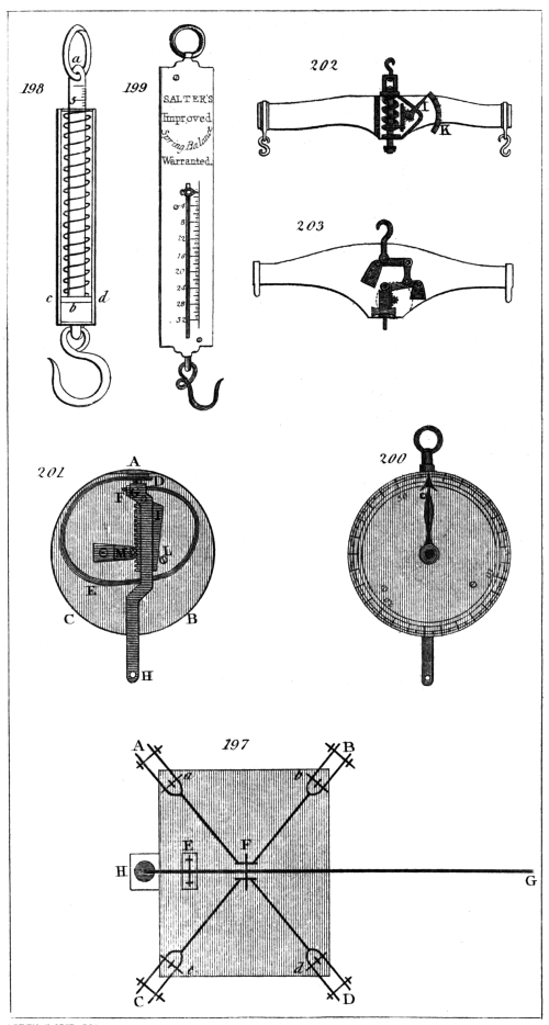
A, B, C, D, represent four levers tending towards the centre of the platform, and each moveable on its fulcrum at A, B, C, D; the fulcrum of each rests upon a piece securely fixed in the corner of the pit. The platform is supported upon the cross pins a, b, c, d, by means of pieces of iron which project from it near its corners, and which are represented in the plate by the short dark lines crossing the pins a, b, c, d. The four levers are connected under the centre of the platform, but not so as to prevent their free motion, and are supported by a long lever at the point F, the fulcrum of which rests upon a piece of masonry at E: the end of this last lever passes below the surface of the road into the turnpike house, and is there attached to one arm of a balance, or, as in Salmon’s patent weighing machine, to a strap passing round a cylinder which winds up a small weight round a spiral, and indicates, by means of an index, the weight placed upon the platform.
Captn. Kater, del. H. Adlard, sc.
London, Pubd. by Longman & Co.
Suppose the distance from A to F to be ten times as great as that from A to a, then a force of one pound applied beneath F would balance ten pounds applied at a, or upon the platform. Again: let the distance from E to G be also ten times greater than the distance from the fulcrum E to F; then a force of one pound applied to raise up the end of the lever G would counterpoise a weight of ten pounds placed upon F. Now, as we gain ten times the power by the first levers, and ten times more by the lever E G, it follows, that a force of one pound tending to elevate G, would balance 100 lbs. placed on the platform; so that if the end of the lever G be attached to one arm of a balance, a weight of 10 lbs. placed in a scale suspended from the other arm, will express the value of 1000 lbs. placed upon the platform. The levers are counterpoised, when the platform is not loaded, by a weight H applied to the end of the last lever, continued beyond the fulcrum for that purpose.
Of Instruments for weighing by means of a Spring.
The spring is well adapted to the construction of a weighing machine, from the property it possesses of yielding in proportion to the force impressed, and consequently giving a scale of equal parts for equal additions of weight. It is liable, however, to suffer injury, unless the steel of which it is composed be very well tempered, from a want of perfect elasticity, and, consequently, from not returning to its original place after it has been forcibly compressed. This, however, must be considered to arise, in a great measure, from imperfection of workmanship, or of the material employed, or from its having been subjected to too great a force.
The Spring Steelyard.
The little instrument known by this name is in very general use, and is particularly convenient where great accuracy is not necessary, as a spring which will ascertain weights from one pound to fifty, is contained in a cylinder only 4 inches long and 3/4 inch diameter.
This instrument is represented at fig. 198. It consists of a tube of iron, of the dimensions just stated, closed at the bottom, to which is attached an iron hook for supporting the substance to be weighed; a rod of iron a b, four tenths of an inch wide and one tenth thick, is firmly fixed in the circular plate c d, which slides smoothly in the iron tube.
A strong steel spring is also fastened to this plate, and passed round the rod a b without touching it, and without coming in contact with the interior of the cylindrical tube. The tube is closed at the top by a circular piece of iron through which the piece a b passes.
Upon the face of a b the weight is expressed by divisions, each of which indicates one pound, and five of such divisions in the instrument now before us occupy two tenths of an inch. The divisions, notwithstanding, are of sufficient size to enable them to be subdivided by the eye.
To use this instrument, the substance to be weighed is suspended by the hook, the instrument being held by a ring passing through the rod at the other end. The spring then suffers a compression proportionate to the weight, and the number of pounds is indicated by the division on the rod which is cut by the top of the cylindrical tube.
Salter’s improved Spring Balance.
A very neat form of the instrument last described has been recently brought before the public by Mr. Salter, under the name of the Improved Spring Balance. It is represented at fig. 199. The spring is contained in the upper half of a cylinder behind the brass plate forming the face of the instrument; and the rod is fixed to the lower extremity of the spring, which is consequently extended, instead of being compressed, by the application of the weight. The divisions, each indicating half a pound, are engraved upon the face of the brass plate, and are pointed out by an index attached to the rod.
Marriott’s Patent Dial Weighing Machine.
The exterior of this instrument is represented at fig. 200., and the interior at fig. 201. A B C is a shallow brass box, having a solid piece as represented at A, to which the spring D E F is firmly fixed by a nut at D. The other end of the spring at F is pinned to the brass piece G H, to the part of which at G is also fixed the iron racked plate I. A screw L serves as a stop to keep this rack in its place. The teeth of the rack fit into those of the pinion M, the axis of which passes through the centre of the dial-plate, and carries an index which points out the weight. The brass piece G H is merely a plate where it passes over the spring, and the tail piece H, to which the weight is suspended, passes through an opening in the side of the box.
Of the Dynamometer.
This is an important instrument in mechanics, calculated to measure the muscular strength exerted by men and animals. It consists essentially of a spring steelyard, such as that we first described. This is sometimes employed alone, and sometimes in combination with various levers, which allow of the spring being made more delicate, and consequently increase the extent of the divisions indicating the weight.
The first instrument of this kind appears to have been invented by Mr. Graham, but it was too bulky and inconvenient for use. M. le Roy made one of a more simple construction. It consisted of a metal tube, about a foot long, placed vertically upon a stand, and containing in the inside a spiral spring, having above it a graduated rod terminating in a globe. This rod entered the tube more or less in proportion to the force applied to the globe, and the divisions indicated the quantity of this force. Therefore, when a man pressed upon the globe with all his strength, the divisions upon the rod showed the number of pounds weight to which it was equal.
An instrument of this kind for determining the force of a blow struck by a man with his fist was lately exhibited at the National Repository. It was fixed to a wall, from which it projected horizontally. In place of the globe there was a cushion to receive the blow, and as the suddenness with which the spring returned rendered it impossible to read the division upon the rod, another rod similarly divided was forced in by the plate forming the basis of the cushion, and remained stationary when the spring returned. The common spring steelyard, however, which we first described, is in principle the same as M. le Roy’s dynamometer, and is much more conveniently constructed for the purpose we are considering. The ring at one end may be fixed to an immovable object, and the hook at the other attached to a man, or to an animal, and the extent to which the graduated rod is drawn out of the cylinder shows at once the force which is applied. Though this is perhaps the best, and certainly the most simple dynamometer, others have been contrived, which are, however, but modifications of the spring steelyard. One of these is represented at fig. 202. The spiral spring acts in the manner before described, but its divisions are increased in size, and therefore rendered more perceptible by means of a rack fixed to the plate, acting against the spiral spring, the teeth of which move a pinion upon which the arm I is fixed, pointing to the graduated arc K.
Another dynamometer has been invented by Mr. Salmon; it is represented at fig. 203. and is a combination of levers with the spring. By means of these levers a much more delicate spring, and which is therefore more sensible, may be employed than in the dynamometer last described.
The manner in which these levers and spring act will be readily understood by an inspection of the figure. Like the weighing machine for carriages, the fulcrum of each lever is at one end, and the force is diminished in passing to the spring, in the ratio of the length of its arms. The spring moves a pinion by means of a rack, upon which pinion a hand is placed, indicating by divisions upon a circular dial-plate, the amount of the force employed.
The spring used in this machine is calculated to weigh only about 50 lbs. instead of about 5 cwt., as in the last described; but by means of the levers which intervene between it and the force applied, it will serve to estimate a force equal to 6 cwt., and might obviously be made to go to a much greater extent, by varying the ratio of the length of the arms of the levers.
ON COMPENSATION PENDULUMS.
(336.) It is said of Galileo that, when very young, he observed a lamp suspended from the roof of a church at Pisa, swinging backwards and forwards with a pendulous motion. This, if it had been remarked at all by an uneducated mind, would, most probably, have been passed by as a common occurrence, unworthy of the slightest notice; but to the mind imbued with science no incident is insignificant; and a circumstance apparently the most trivial, when subjected to the giant force of expanded intellect, may become of immense importance to the improvement and to the well-being of man. The fall of an apple, it is said, suggested to Newton the theory of gravitation, and his powerful mind speedily extended to all creation that great law which brings an apple to the ground. The swinging of a lamp in a church at Pisa, viewed by the piercing intellect of Galileo, gave rise to an instrument which affords the most perfect measure of time, which serves to determine the figure of the earth, and which is inseparably connected with all the refinements of modern astronomy.
The properties of the pendulum, and the manner in which it serves to measure time, have been fully explained in chapter xi.; and if a substance could be found not susceptible of any change in its dimensions from a change of temperature, nothing more would be necessary, as the centre of oscillation would always remain at the same distance from the point of suspension. As every known substance, however, expands with heat, and contracts with cold, the length of the pendulum will vary with every alteration of temperature, and thus the time of its vibration will suffer a corresponding change. The effect of a difference of temperature of 25°, or that which usually occurs between winter and summer, would occasion a clock furnished with a pendulum having an iron rod to gain or lose six seconds in twenty-four hours.
It became, then, highly important to discover some means of counteracting this variation to which the length of the pendulum was liable, or, in other words, to devise a method by which the centre of oscillation should, under every change of temperature, remain at the same distance from the point of suspension: happily, the difference in the rate of expansion of different metals presented a ready means of effecting this.
Graham, in the year 1715, made several experiments to ascertain the relative expansions of various metals, with a view of availing himself of the difference of the expansions of two or more of them when opposed to each other, to construct a compensating pendulum. But the difference he found was so small, that he gave up all hope of being able to accomplish his object in that way. Knowing, however, that mercury was much more affected by a given change of temperature than any other substance, he saw that if the mercury could be made to ascend while the rod of the pendulum became longer, and vice versâ, the centre of oscillation might always be kept at the same distance from the point of suspension. This idea happily gave birth to the mercurial pendulum, which is now in very general use.
Captn. Kater, del. H. Adlard, sc.
London, Pubd. by Longman & Co.
In the mean time, Graham’s suggestion excited the ingenuity of Harrison, originally a carpenter at Barton in Lincolnshire, who, in 1726, produced a pendulum formed of parallel brass and steel rods, known by the name of the gridiron pendulum.
In the mercurial pendulum, the bob or weight is the material affording the compensation; but in the gridiron pendulum the object is attained by the greater expansion of the brass rods, which raise the bob upwards towards the point of suspension as much as the steel rods elongate downwards.
In the present article, we shall describe such compensation pendulums as appear to us likely to answer best in practice; and we trust we shall be able to simplify the subject so as to render a knowledge of mathematics in the construction of this important instrument unnecessary.
The following table contains the linear expansion of various substances in parts of their length, occasioned by a change of temperature amounting to one degree. We have taken the liberty of extracting it from a very valuable paper by F. Bailey, Esq., on the mercurial compensation pendulum, published in the Memoirs of the Astronomical Society of London for 1824.
TABLE I.
Linear Expansion of various Substances for One Degree of Fahrenheit’s Thermometer.
Substances. Expansions. Authors.
White Deal, ·0000022685 Captain Kater.

·0000028444 Dr. Struve.
English Flint Glass, ·0000047887 Dulong and Petit.
Iron (cast), ·0000061700 General Roy.
·0000065668 Dulong and Petit.
Iron (wire), ·0000068613 Lavoisier and L.
Iron (bar), ·0000069844 Hasslar.
Steel (rod), ·0000063596 General Roy.
Brass, ·0000104400 Commissioners of Weights and Measures —mean of several experiments.

Lead, ·0000159259 Smeaton.
Zinc, ·0000163426 Ditto.
Zinc (hammered), ·0000172685 Ditto.
Mercury in bulk, ·00010010 Dulong and Petit.
From this table it is easy to determine the length of a rod of any substance the expansion of which shall be equal to that of a rod of given length of any other substance.
The lengths of such rods will be inversely proportionate to their expansions. If, therefore, we divide the lesser expansion by the greater (supposing the rod the length of which is given to be made of the lesser expansible material), and multiply the given length by this quotient, we shall have the required length of a rod, the expansion of which will be equal to that of the rod given. For example:—The expansion of a rod of steel being, from the above table, ·0000063596, and that of brass, ·0000104400; if it were required to determine the length of a rod of brass which should expand as much as a rod of steel of 39 inches in length, we have ·0000063596/·0000104400 = ·6091, which, multiplied by 39, gives 23·75 inches for the length of brass required.
We shall here, in order to facilitate calculation, give the ratio of the lengths of such substances as may be employed in the construction of compensation pendulums.
TABLE II.
Steel rod and brass compensation, as 1: ·6091
Iron wire rod and lead compensation, ·4308
Steel rod and lead compensation, ·3993
Iron wire rod and zinc compensation, ·3973
Steel rod and zinc compensation, ·3682
Glass rod and lead compensation, ·3007
Glass rod and zinc compensation, ·2773
Deal rod and lead compensation, ·1427
Deal rod and zinc compensation, ·1313
Steel rod and mercury in a steel cylinder, ·0728
Steel rod and mercury in a glass cylinder, ·0703
Glass rod and mercury in a glass cylinder, ·0529
It is evident that in this table the decimals express the length of a rod of the compensating material, the expansion of which is equal to that of a pendulum rod whose length is unity.
As we are not aware of the existence of any work which contains instructions that might enable an artist or an amateur to make a compensation pendulum, we shall endeavour to give such detailed information as may free the subject from every difficulty.
The pendulum of a clock is generally suspended by a spring, fixed to its upper extremity, and passing through a slit made in a piece which is called the cock of the pendulum. The point of suspension is, therefore, that part of the spring which meets the lower surface of the cock. Now the distance of the centre of oscillation of the pendulum from this point may be varied in two ways; the one by drawing up the spring through this slit, and the other by raising the bob of the pendulum. Either of these methods may be practised in the compensation pendulum, but the former is subject to objections from which the latter is exempt.
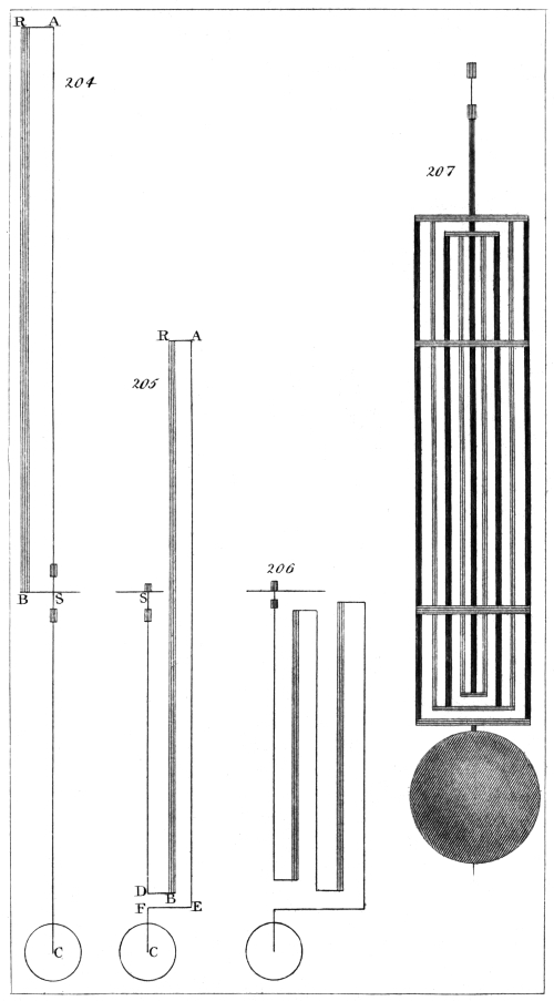
Suppose it were required to compensate a pendulum of 39 inches in length, of steel, by means of the expansion of a brass rod. Here, referring to fig. 204., we have S C 39 inches (which is to remain constant) of steel; the pendulum spring, passing through the cock at S, is attached to another rod of steel, which is fixed to the cross piece R A at A. The other end of the cross piece at R is fastened to a brass rod, the lower extremity of which is fixed to the cock of the pendulum at B. Now the brass rod B R must expand upwards, as much as the steel rod A C expands downwards; and the length of the brass must be such as to effect this, leaving 39 inches of the steel rod below the cock of the pendulum.
Let us first try 80 inches of steel. Multiplying this by ·6091, we have 48·73 inches for the length of brass, which compensates 80 inches of steel. But as 48·73 inches of the steel, equal in length to the brass, would in this case be above the cock of the pendulum, it would leave only 31·27 inches below it, instead of 39 inches.
Let us now try 100 inches of steel. This, multiplied as before by ·6091, gives 60·91 inches, according to the expansions which we have used, for the length of the brass rod, and leaves 39·09 inches below the cock of the pendulum, which is sufficiently near for our present purpose.
From what has been said we may perceive that the total length of the material of which the pendulum rod is composed must be always equal to the length of the pendulum added to the length of the compensation.
In this instance we have effected our object, by drawing the pendulum-spring through the slit; but we will now show how the same thing may be done by moving the bob of the pendulum. At fig. 205., let S C, as before, be equal to 39 inches. Let the steel rod S D turn off at right angles at D, and let a rod of brass B R, of 61 inches in length, ascend perpendicularly from this cross piece to R. To the upper part of the brass rod fix another cross piece R A, and from the extremity A let a steel rod descend to E, bending it as in the figure till it reaches C. Now the total length of the pieces of steel expanding downwards is equal to S D, D F, and F C (amounting together to 39 inches), to which must be added a length of steel equal to that of the brass rod B R, (61 inches), making together 100 inches of steel as before, the expansion of which downwards is compensated by that of the brass rod, of 61 inches in length, expanding upwards.
This form, however, is evidently inconvenient, from the great length of brass and steel which is carried above the cock of the pendulum; but it is the same thing whether the brass and steel be each in one piece, or divided into several, provided the pieces of steel be all so arranged as to expand downwards, and those of brass upwards. Thus, at fig. 206., the portions of steel expanding downwards are together equal, as before, to 100 inches, and the two brass pieces expanding upwards are together equal to 61 inches. So that, in fact, the two last forms of compensation which we have described differ in no respect from each other in principle, but only in the arrangement of the materials. The last is the half of the gridiron pendulum, the remaining bars being merely duplicates of those we have described, and serving no other purpose but to form a secure frame-work.
Harrison’s Gridiron Pendulum.
After what has been said, little more is necessary than to give a representation of this pendulum. This is done at fig. 207., in which the darker lines represent the steel rods, and the lighter those of brass. The central rod is fixed at its lower extremity to the middle of the third cross piece from the bottom, and passes freely through holes in the cross pieces which are above, whilst the other rods are secured near their extremities to the cross pieces by pins passing through them. In order to render the whole more secure, the bars pass freely through holes made in two other cross pieces, the extremities of which are fixed to the exterior steel wires. As different kinds of the same metal vary in their rate of expansion, the pendulum when finished may be found upon trial to be not duly compensated. In this case one or more of the cross pieces is shifted higher or lower upon the bars, and secured by pins passed through fresh holes.
Troughton’s Tubular Pendulum.
This is an admirable modification of Harrison’s gridiron pendulum. It is represented at fig. 208., where it may be seen that it has the appearance of a simple pendulum, as the whole compensation is concealed within a tube six tenths of an inch in diameter.
A steel wire, about one tenth of an inch in diameter, is fixed in the usual manner to the spring by which the pendulum is suspended. This wire passes to the bottom of an interior brass tube, in the centre of which it is firmly screwed. The top of this tube is closed, the steel rod passing freely through a hole in the centre. Into the top of this interior tube two steel wires, of one tenth of an inch in diameter, are screwed into holes made in that diameter, which is at right angles to the motion of the pendulum. These wires pass down the tube without touching either it or the central rod, through holes made in the piece which closes the bottom of the interior tube. The lower extremities of these wires, which project a little beyond the inner tube, are securely fixed in a piece which closes the bottom of an exterior brass tube, which is of such a diameter as just to allow the interior tube to pass freely through it, and of a sufficient length to extend a little above it. The top of the exterior tube is closed like that of the interior, having also a hole in its centre, to allow the first steel rod to pass freely through it. Into the top of the exterior tube, in that diameter which coincides with the motion of the pendulum, a second pair of steel wires of the same diameter as the former are screwed, their distance from the central rod being equal to the distance of each from the first pair. They consequently pass down within the interior tube, and through holes made in the pieces closing the lower ends of both the interior and exterior tubes. The lower ends of these wires are fastened to a short cylindrical piece of brass of the same diameter as the exterior tube, to which the bob is suspended by its centre.
Captn. Kater, del. H. Adlard, sc.
London, Pubd. by Longman & Co.
Fig. 209. is a full sized section of the rod; the three concentric circles represent the two tubes, and the rectangular position of the two pair of wires round the middle one is shown by the five small circles.
Fig. 210. is the part which closes the upper end of the interior tube. The two small circles are the two wires which proceed from it, and the three large circles show the holes through which the middle wire and the other pair of wires pass.
Fig. 211. is the bottom of the interior tube. The small circle in the centre is where the central rod is fastened to it, the others the holes for the other four wires to pass through.
Fig. 212. is the part which closes the top of the external tube. In the large circle in the centre a small brass tube is fixed, which serves as a covering for the upper part of the middle wire, and the two small circles are to receive the wires of the last expansion.
Fig. 213. represents the bottom of the exterior tube, in which the small circles show the places where the wires of the second expansion are fastened, and the larger ones the holes for the other pair of wires to pass through.
Fig. 214. is a cylindrical piece of brass, showing the manner in which the lower ends of the wires of the last expansion are fastened to it, and the hole in the middle is that by which it is pinned to the centre of the bob. The upper ends of the two pair of wires are, as we have observed, fastened by screwing them into the pieces which stop up the ends of the tubes, but at the lower ends they are all fixed as represented in fig. 214. The pieces represented by figs. 213. and 214. have each a jointed motion, by means of which the fellow wires of each pair would be equally stretched, although they were not exactly of the same length.
The action of this pendulum is evidently the same as that of the gridiron pendulum, as we have three lengths of steel expanding downwards, and two of brass expanding upwards. The weight of the pendulum has a tendency to straighten the steel rods, and the tubular form of the brass compensation effectually precludes the fear of its bending; an advantage not possessed by the gridiron pendulum, in which brass rods are employed.
Mr. Troughton, to the account he has given of this pendulum in Nicholson’s Journal, for December, 1804, has added the lengths of the different parts of which it was composed, and the expansions of brass and steel from which these lengths were computed. The length of the interior tube was 31·9 inches, and that of the exterior one 32·8 inches, to which must be added 0·4, the quantity by which in this pendulum the centre of oscillation is higher than the centre of the bob. These are all of brass. The parts which are of steel are,—the middle wire, which, including 0·6, the length of the suspension spring, is 39·3 inches. The first pair of wires 32·5 inches; and the second pair, 33·2 inches. The expansions used were, for brass ·00001666, and for steel ·00000661, in parts of their length for one degree of temperature.
Benzenberg’s Pendulum.
This pendulum is mentioned in Nicholson’s Journal for April, 1804, and is taken from Voigt’s Magazin für den Neuesten Zustande der Naturkunde, vol. iv. p. 787. The compensation appears to have been effected by a single rod of lead in the centre, of about half an inch thick; the descending rods were made of the best thick iron wire.
As this pendulum deserves attention from the ease with which it may be made, and as others which have since been produced resemble it in principle, we have given a representation of it at fig. 215., where A B C D are two rods of iron wire riveted into the cross pieces A C B D. E F is a rod of lead pinned to the middle of the piece B D, and also at its upper extremity to the cross piece G H, into which the second pair of iron wires are fixed, which pass downwards freely through holes made in the cross piece B D. The lower extremities of these last iron wires are fastened into the piece K L, which carries the bob of the pendulum.
To determine the length of lead necessary for the compensation, we must recollect, as before, that the distance from the point of suspension to the centre of the bob (speaking always of a pendulum intended to vibrate seconds) must be 39 inches. Let us suppose the total length of the iron wire to be 60 inches; then, from the table which we have given, we have ·4308 for the length of a rod of lead, the expansion of which is equivalent to that of an iron rod whose length is unity. Multiplying 60 inches by ·4308, we have 25·84 inches of lead, which would compensate 60 inches of iron; but this, taken from 60 inches, leaves only 34·16 instead of 39 inches. Trying again, in like manner, 68·5 inches of iron, we find 29·5 inches of lead for the length, affording an equivalent compensation, and which, taken from 68·5 inches, leaves 39 inches.
The length of the rod of lead then required as a compensation in this pendulum is about 291/2 inches.
The writer of this article would suggest another form for this pendulum, which has the advantage of greater simplicity of construction.
S A, fig. 216., is a rod of iron wire, to which the pendulum spring is attached. Upon this passes a cylindrical tube of lead, 291/2 inches long, which is either pinned at its lower extremity to the end of the iron rod S A, or rests upon a nut firmly screwed upon the extremity of this rod.
A tube of sheet iron passes over the tube of lead, and is furnished at top with a flanche, by which it is supported upon the leaden tube; or it may be fastened to the top of this tube in any manner that may be thought convenient.
The bob of the pendulum may be either passed upon the iron tube (continued to a sufficient length) and secured by a pin passing through the centre of the bob, or the iron tube may be terminated by an iron wire serving the same purpose.
Here we have evidently the same expansions upwards and downwards as in the gridiron form, given to this pendulum by Mr. Benzenberg, joined to the compactness of Troughton’s tubular pendulum.
Ward’s Compensation Pendulum.
In the year 1806, Mr. Henry Ward, of Blandford in Dorsetshire, received the silver medal of the Society of Arts for the compensation pendulum which we are about to describe.
Fig. 217. is a side view of the pendulum rod when together. H H and I I are two flat rods of iron about an eighth of an inch thick. K K is a bar of zinc placed between them, and is nearly a quarter of an inch thick. The corners of the iron bars are bevelled off, which gives them a much lighter appearance. These bars are kept together by means of three screws, O O O, which pass through oblong holes in the bars H H and K K, and screw into the rod I I. The bar H H is fastened to the bar of zinc K K, by the screw m, which is called the adjusting screw. This screw is tapped into H H, and passes just through K K; but that part of the screw which passes K K has its threads turned off. The iron bar I I has a shoulder at its upper end, and rests on the top of the zinc bar K K and is wholly supported by it. There are several holes for the screw m, in order to adjust the compensation.
The action of this pendulum is similar to that last described, the zinc expanding upwards as much as the iron rods expand downwards, and consequently the instance from the point of suspension to the centre of oscillation remains the same.
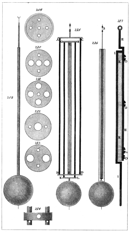
Captn. Kater, del. H. Adlard, sc.
London, Pubd. by Longman & Co.
Mr. Ward states that the expansion of the zinc he used (hammered zinc) was greater than that given in the tables. He found that the true length of the zinc bar should be about 23 inches; our computation would make it nearly 26.
The Compensation Tube of Julien le Roy.
We mention this merely to state that it is similar in principal to the apparatus represented at fig. 204., with merely this difference, that, instead of the steel rod being fixed to a cross piece proceeding from the brass bar B R, it is attached to a cap fixed upon a brass tube (through which it passes) of the same length as that of the brass rod B R. Cassini spoke well of this pendulum, and it was used in the observatory of Cluny about the year 1748.
Deparcieux’s Compensation.
This was contrived in the same year as that invented by Julien le Roy. It is represented at fig. 218., where A B D F is a steel bar, the ends of which are to be fixed to the lower sides of pieces forming a part of the cock of the pendulum. G E I H is of brass, and stands with its extremities resting on the horizontal part B D of the steel frame. The upper part E I of the brass frame passes above the cock of the pendulum, and admits the tapped wire K, to which the pendulum spring is fixed through a squared hole in the middle. A nut upon this tapped wire gives the adjustment for time. The spring passes through the slit in the cock in the usual manner.
It may be easily perceived that this pendulum is in principle the same as that of Le Roy; the expansion of the total length of steel A B S C downwards being compensated by the equivalent expansion of the brass bar G E upwards. It is, however, preferable to Le Roy’s, because the compensation is contained in the clock case.
Deparcieux had previously published, in the year 1739, an improvement of an imperfectly compensating pendulum, proposed in the year 1733 by Regnauld, a clockmaker of Chalons. In this pendulum Deparcieux employed a lever with unequal arms to increase the effect of the expansion of the brass rod, which was too short.
We may here remark, that all fixed compensations are liable to the same objection, namely, that of not moving with the pendulum, and therefore not taking precisely the same temperature.
Captain Kater’s Compensation Pendulum.
In Nicholson’s Journal, for July, 1808, is the description of a compensation pendulum by the writer of this article. In this pendulum the rod is of white deal, three quarters of an inch wide, and a quarter of an inch thick. It was placed in an oven, and suffered to remain there for a long time until it became a little charred. The ends were then soaked in melted sealing-wax; and the rod, being cleaned, was coated several times with copal varnish. To the lower extremity of the rod a cap of brass was firmly fixed, from which a strong steel screw proceeded for the purpose of regulating the pendulum for time in the usual manner.
A square tube of zinc was cast, seven inches long and three quarters of an inch square; the internal dimensions being four tenths of an inch. The lower part of the pendulum rod was cut away on the two sides, so as to slide with perfect freedom within the tube of zinc. To the bottom of this zinc tube a piece of brass a quarter of an inch thick was soldered, in which a circular hole was made nearly four tenths of an inch in diameter, having a screw on the inside. A cylinder of zinc, furnished with a corresponding screw on its surface, fitted into this aperture, and a thin plate of brass screwed upon the cylinder, served as a clamp to prevent any shake after the length of zinc necessary for compensation should have been determined. A hole was made through the axis of the cylinder, through which passed the steel screw terminating the pendulum rod.
An opening was made through the bob of the pendulum, extending to its centre, to admit the square tube of zinc which was fixed at its upper extremity to the centre of the bob. The pendulum rod passed through the bob in the usual manner, and the whole was supported by a nut on the steel screw at the extremity.
In this form the compensation acts immediately upon the centre of the bob, elevating it along the rod as much as the rod elongates downwards: the method of calculating the length of the required compensation is precisely the same as that we have before given.
Assuming the length of the deal rod to be 43 inches, and multiplying this by ·1313 from Table II., we have 5·64 inches for the length of the zinc necessary to counteract the expansion of the deal. The length of the steel screw between the termination of the pendulum rod and the nut was two inches, and that of the suspension spring one inch. Now, 3 inches of steel multiplied by ·3682 would give 1·10 inches for the length of zinc which would compensate the steel, and, adding this to 5·64 inches, we have 6·74 inches for the whole length of zinc required.
In this pendulum, the length of the compensating part may be varied by means of the zinc cylinder furnished with a screw for that purpose. The bob of this pendulum and its compensation are represented at fig. 219.
It has been objected to the use of wooden pendulum rods, that it is difficult, if not impossible, to secure them from the action of moisture, which would at once be fatal to their correct performance. The pendulum now before us has, however, been going with but little intermission since it was first constructed: it is attached to a sidereal clock, not of a superior description, and exposed to very considerable variations of moisture and dryness; yet the change in its rate has been so very trifling as to authorize the belief that moisture has little or no effect upon a wooden rod prepared in the manner we have described. Its rate, under different temperatures, shows that it is over-compensated; the length of the zinc remaining, as stated in Nicholson’s Journal 7·42 inches, instead of which it appears, by our present compensation, that it should be 6·78 inches.
Reid’s Compensation Pendulum.
Mr. Adam Reid of Woolwich presented to the Society of Arts, in 1809, a compensation pendulum, for which he was rewarded with fifteen guineas. This pendulum is the same in principle with that last described; the rod, however, is of steel instead of wood, and the compensation possesses no means of adjustment. This pendulum is represented at fig. 220., where S B is the steel rod, a little thicker where it enters the bob C, and of a lozenge shape to prevent the bob turning, but above and below it is cylindrical.
A tube of zinc D passes to the centre of the bob from below, and the bob is supported upon it by a piece which crosses its centre, and which meets the upper end of the tube.
The rod being passed through the bob and zinc tube, a nut is applied upon a screw at the lower extremity of the rod in the usual manner. If the compensation should be too much, the zinc tube is to be shortened until it is correct.
The length of the zinc tube will be the same in this pendulum as in that of Mr. Ward—about 23 inches, if his experiments are to be relied upon.
The objection to this pendulum appears to be its great length, which amounts to 62 inches. We conceive it would be preferable to place the zinc above the bob, as in the modification which we have suggested of Benzenberg’s pendulum.
Ellicott’s Pendulum.
It appears that the idea of combining the expansions of different metals with a lever, so as to form a compensation pendulum, originated with Mr. Graham; for Mr. Short, in the Philosophical Transactions for 1752, states that he was informed by Mr. Shelton, that Mr. Graham, in the year 1737, made a pendulum, consisting of three bars, one of steel between two of brass; and that the steel bar acted upon a lever so as to raise the pendulum when lengthened by heat, and to let it down when shortened by cold.
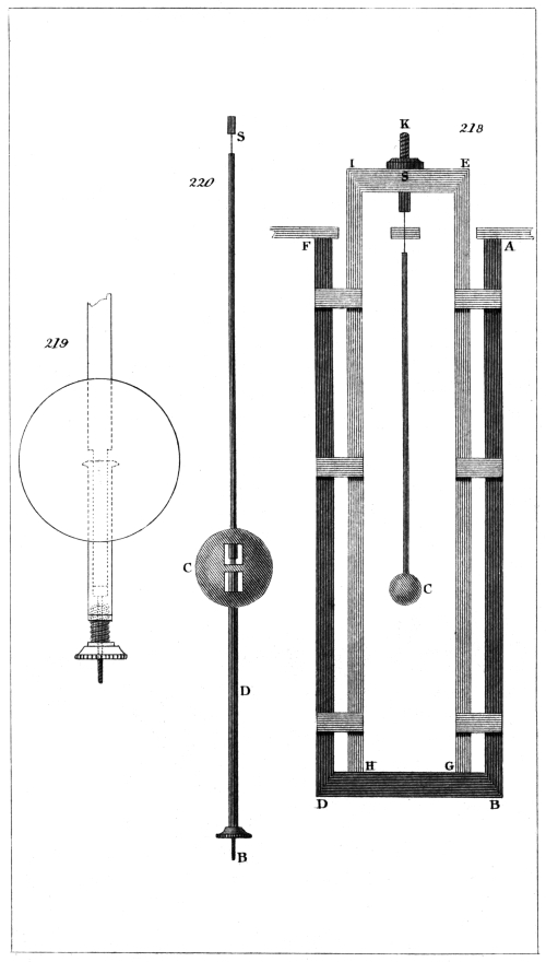
Captn. Kater, del. H. Adlard, sc.
London, Pubd. by Longman & Co.
This pendulum, however, was found upon trial to move by jerks, and was therefore laid aside by the inventor to make way for the mercurial pendulum.