Note D — G.
Reading edition
GAS-LIGHT. (Eclairage par gas, Fr.; Gaslicht, Germ.) Dr. Clayton demonstrated, by numerous experiments in 1737 and 1738, that bituminous pit-coal, subjected to a red heat in close vessels, afforded a great deal of an air similar to the fire-damp of mines, but which burned with a brighter flame. It does not appear that this species of factitious air was ever produced from pit-coal for the purpose of artificial illumination till 1792, when Mr. William Murdoch, engineer to Messrs. Bolton and Watt, employed coal gas for lighting his house and offices, at Redruth in Cornwall. The gas was generated in an iron retort, whence it was received in a gasometer, distributed in different situations by pipes, and finally burned at small apertures which could be opened and stopped at pleasure. He moreover made this light movable, by confining the gas in portable tin-plate vessels, and burning it wherever he pleased. Between this period and 1802, Mr. Murdoch continued at intervals to make similar experiments; and upon occasion of the national illumination in the spring of the latter year, at the peace of Amiens, he lighted up part of the Soho manufactory with a public display of gas lights.
The earliest application of this artificial light, on a large systematic scale, was made at Manchester; where an apparatus for lighting the great cotton mills of Messrs. Philips and Lee, was fitted up in 1804 and 1805, under the direction of Mr. Murdoch. A quantity of light, nearly equal to 3000 candles, was produced and distributed in this building. This splendid pattern has been since followed very generally in Great Britain, and more or less in many parts of the continents of Europe and America. By the year 1822, gas-lighting in London had become the business of many public companies. At the Peter-street station, for example, 300 retorts had been erected, supplying 15 gasometers, having each an average capacity of 20·626 cubic feet, but, being never quite filled, their total contents in gas might be estimated at 309,385 cubic feet. The extent of main pipes of distribution belonging to this station was then about 57 miles, with two separate mains in some of the streets. The product of gas was from 10,000 to 12,000 cubic feet from a chaldron of coals. The annual consumption of coals was therefore altogether 9282 chaldrons, affording 11,384,000 cubic feet of gas, allowing 153 retorts to be in constant daily action, upon an average of the year; and illuminating 10,660 private lamps, 2248 street lamps, and 3894 theatre lamps.
At the Brick-lane works, 371 retorts were fixed in 1822, 133 being worked on an average of summer and winter. There were 12 gasometers, charged with an average quantity of gas amounting to 197,214 cubic feet. Of coals, 8060 chaldrons were annually consumed; 96,720,000 cubic feet of gas were generated; for the supply of 1978 public lamps, and 7366 private ones, connected with main pipes 40 miles long.
At the Curtain-road gas establishment, there were 240 retorts; but the greatest number worked in 1821 was only 80, and the lowest 21. The six gasometers had an average contents of 90,467 cubic feet. Of coals, 3336 chaldrons were annually consumed, yielding 40,040,000 cubic feet of gas, that supplied 3860 private lamps, and 629 public ones, by means of mains 25 miles long. The above three stations belonged to the London Gas Light and Coke Company.
The City of London Gas Light Company, Dorset-street, had built up 230 retorts, and 6 gasometers, while two were preparing; having a total capacity of 181,282 cubic feet. Of private lamps 5423 were lighted, and 2413 public ones, from mains extending 50 miles. The quantity of coals carbonized amounted to 8840 chaldrons; producing 106,080,000 cubic feet of gas.
The South London Gas Light and Coke Company had mounted at Bankside 143 retorts, with 3 gasometers; the contents of the whole being 41,110 cubic feet, connected with mains from 30 to 40 miles long. At their other station, in Wellington-street, 3 large gasometers were then erecting, with a capacity of 73,565 cubic feet, which were to be supplied with gas from Bankside, till retorts were mounted for them.
The Imperial Gas Light and Coke Company had at that time 6 gasometers in progress at their Hackney station.
In 1822 there were thus four great companies, having in all 47 gasometers at work, capable of containing 917,940 cubic feet of gas, supplied by 1315 retorts, which generated per annum upwards of 397,000,000 cubic feet of gas, by which 61,203 private lamps, and 7268 public or street lamps, were lighted in the metropolis. Besides these public companies, there were likewise several private ones.
1. Of the generation of illuminating gases.—Pure hydrogen gas burns with too feeble a flame to be employed for illumination. But carburetted hydrogen having the property of precipitating its carbon in the act of burning, its solid particles become incandescent, and diffuse a vivid light. The more carbon it contains, the more brightly does it burn. This gas exists in two distinct states of combination. In the first, two measures of hydrogen gas are combined with one measure of the vapour of carbon, forming together one measure whose specific gravity is of course the sum of the weights of the constituents, or 0·559; atmospherical air being 1·000. This is the gas which is found in mines, and is also evolved in ditches from decomposing vegetable matter. In the second, two measures of hydrogen gas are combined with two of gaseous carbon, forming also one volume or measure whose weight or specific gravity is 0·985. This was at one time called the olefiant gas, because when mixed with chlorine an oily looking compound was produced. It may be called as well oil gas, because it is generated in considerable quantities by the igneous decomposition of oil. Thus the olefiant gas contains in the same volume double the quantity of carbon of common carburetted hydrogen, and it burns with a proportionably brighter flame. The gaseous oxide of carbon, as well as sulphuretted hydrogen gas, burns with a feeble blue light, but the latter produces in combustion sulphurous acid, an offensive and noxious gas.
By dry distillation or carbonization in close vessels, all bodies of vegetable and animal origin disengage carburetted hydrogen gas; even charcoal when placed in ignition in contact with steam, by decomposing the water, produces abundance of carbonic acid, carburetted hydrogen, hydrogen, and carbonic oxide. After separating the carbonic acid with lime water, that mixed gas contains in 100 measures, 20 of carburetted hydrogen; the rest being hydrogen and carbonic oxide, so that the gaseous mixture cannot be used for illumination. The best substances for furnishing a gas rich in luminifereous materials are, pitcoal, especially the cannel coal, resin, oil, fats of all kinds, tar, wax, &c. In some cases the gases evolved during the igneous decomposition of bones and other animal matters for the production of ammonia, may be employed for procuring light, but they are apt to emit a fetid odour.
When coals are heated in a cast-iron retort to ignition, the progress of decomposition is as follows. First, and before the retort becomes red hot, steam issues along with the atmospheric air. When the retort begins to redden, tar distils in considerable quantity with some combustible gas, of which hydrogen mixed with ammoniacal gas forms a part. The evolution of gas increases as the retort becomes hotter, with a continual production of tar and ammoniacal liquor as well as sulphurous acid from the pyrites of the coal, which unites with the ammonia. When the retort has come to a bright cherry red heat, the disengagement of gas is most active. By and bye the gaseous production diminishes, and eventually ceases entirely, although the heat be increased. In the retort a quantity of carbonized coal or coke remains, while tar is found at the bottom of the receiver, covered with the ammoniacal liquor, and combined with carbonic and sulphurous acids, and sulphuretted hydrogen.
If during this distillation, the combustible gas be collected and examined at the several stages of the process, it is found to differ extremely in its luminiferous powers. That which comes off before the retort has acquired its proper temperature, gives a feeble light, and resembles the gas obtained by the ignition of moist charcoal, consisting chiefly of hydrogen. That evolved when the retort has just acquired throughout a vivid red heat, is the best of all, consisting chiefly of bicarburetted hydrogen or olefiant gas. From good coal, it consists, for example in 100 measures, of 13 of olefiant gas, 82·5 of carburetted hydrogen, 3·2 carbonic oxide, 1·3 azote; the mixture having a specific gravity of 0·650. At a later period, as after 5 hours, it contains 7 measures of olefiant gas, 56 of carburetted hydrogen, 11 of carbonic oxide, 21·3 of hydrogen, 4·7 of azote; the specific gravity of the whole being 0·500. Towards the end of the operation, as after 10 hours, it contains twenty measures of carburetted hydrogen, 10 of carbonic oxide, 60 of hydrogen, 10 of azote, with a specific gravity of only 0·345. The hydrogen becomes sulphuretted hydrogen, if there be much pyritous matter in the coal. The larger proportion of the gas is disengaged during the first hour, amounting to about one fifth of the whole; in the three following hours the disengagement is tolerably uniform, constituting in all fifty-four hundredths; in the sixth hour, it is one tenth; in the seventh and eighth hours, sixteen hundredths.
From these observations are derived the rules for the production of a good light gas from coals. They show that the distillation should commence with a retort previously heated to a cherry red, since thereby good gas is immediately produced, and a portion of the tar is also converted into gas, instead of being simply distilled over into the condenser pit; that this heat should be steadily continued during the whole operation, from 5 to 8 hours; that it should not be increased, especially towards the end, for fear of generating carbonic oxide and hydrogen gases, as well as of injuring the retort when the cooling agency of gasefication has become feeble; and that the operation should be stopped some time before gas ceases to come over, lest gases with feeble illuminating power should impoverish the contents of the gasometer. Upon the average, a pound of good coal affords four cubic feet of gas, or a chaldron = 26 cwt. London measure, affords from 12,000 to 15,000 cubic feet, according to the form of the retort, and the manner of firing it.
When oil, fats, rosin, tar, &c. are employed for the production of a light gas, it is not sufficient to introduce these substances into the retorts, and to heat them, as is done with coals. In this case, the greater part of them would distil over in the state of volatile oils, and very little gas be generated, only as much as corresponded to the quantity of fat, &c. in immediate contact with the retort. It becomes therefore necessary to fill the retorts with pieces of brick or coke; and to keep them in ignition, while the oil, &c. is slowly introduced into their interior. The fats instantly assume the vaporous state, and thus coming into contact upon an extensive surface with the ignited bricks, are decomposed into combustible gases. A small portion of carbonaceous matter remains in the retort, while much olefiant gas is formed, possessing a superior illuminating power to common coal gas, and entirely free from sulphureous impregnation. The best oil gas is generated at a dull red, a heat much below what is requisite for the decomposition of coal. A more intense heat would indeed produce a greater volume of gas, but of a poorer quality, because the olefiant gas thereby deposits one half of its carbon, and is converted into common carburetted hydrogen. Oil affords at a lively red heat, gases which contain in 100 measures, 19 of olefiant gas, 32·4 of carburetted hydrogen, 12·2 of carbonic oxide gas, 32·4 of hydrogen, and 4 of azote; the mean specific gravity being only 0·590. At a more moderate temperature it yields 22·5 of the olefiant, 50·3 carburetted hydrogen, 15·5 carbonic oxide, 7·7 hydrogen, and 4 azote, with a specific gravity of 0·758. It contains when generated by dull ignition, as is usual in works on the manufacturing scale, in 100 parts, from 38 to 40 of olefiant gas, and besides the carburetted hydrogen, a few per cents. of carbonic oxide and azote, with a specific gravity of 0·900, and even upwards. One pound of oil or fluid fat affords 15 cubic feet of gas; of tar affords about 12 cubic feet; of rosin or pitch, 10 cubic feet.
When the oil gas is compressed by a force of from 15 to 20 atmospheres, as was the practice of the Portable Gas Company, about one fifth of the volume of the gas becomes liquefied into an oily, very volatile fluid, having the specific gravity 0·821. It is a mixture of three fluids (consisting of carburetted hydrogen), of different degrees of volatility. The most volatile of these boils even under 32° F. Some of the vapour of this gas-oil is mixed with the olefiant gas in the general products of decomposition; in consequence of which they are sometimes richer in carbon than even olefiant gas, and have a higher illuminating power. Oil gas contains about 22 per cent. and coal gas about 31⁄4 per cent. of this oily vapour. In the estimations of the composition of the gases given above, this vapour is included under olefiant gas. This vapour combines readily with sulphuric acid, and is thus precipitated from the gaseous mixture. The amount of olefiant gas is shown, by adding to the gas, contained over water, one half of its volume of chlorine, which, in the course of an hour or two, condenses the olefiant gas into an oily looking liquid (chloride of hydrocarbon.) After the mixture, the gases must be screened from the light, otherwise the common carburetted hydrogen would also combine with the chlorine, while water and carbonic acid would make their appearance.
The oil employed for affording gas is the crudest and cheapest that can be bought; even the blubber and sediment of whale oil are employed with advantage. After all, however, coal is so much cheaper, and the gas produced from it is now so well purified, that oil and rosin are very little used in gas apparatus.
Apparatus for Coal Gas.—Coal gas, as it issues from the retort, cannot be directly employed for illumination; for it contains vapours of tar and coal oil, as also steam impregnated with the carbonate, sulphite, and hydrosulphuret of ammonia. These vapours would readily condense in the pipes through which the gas must be distributed, and would produce obstructions; they must therefore be so far removed by previous cooling, as to be liable to occasion no troublesome condensation at ordinary temperatures. The crude coal gas contains moreover sulphuretted hydrogen, whose combustion for light would exhale an offensive sulphureous odour, that ought to be got rid of as much as possible. Carbonic acid and carbonic oxide gases, generated at first from the decomposition of the steam by the ignited coal, enfeeble the illuminating power of the gas, and should be removed. The disengagement of gas in the retorts is never uniform, but varies with the degree of heat to which they are exposed; for which reason the gas must be received in a gasometer, where it may experience uniform pressure, and be discharged uniformly into the pipes of distribution, in order to ensure a steady discharge of gas, and uniform intensity of light in the burners. A coal gas apparatus ought therefore to be so constructed as not only to generate the gas itself, but to fulfil the above conditions.
In fig. 482., such an apparatus is represented, where the various parts are shown connected with each other, in section.
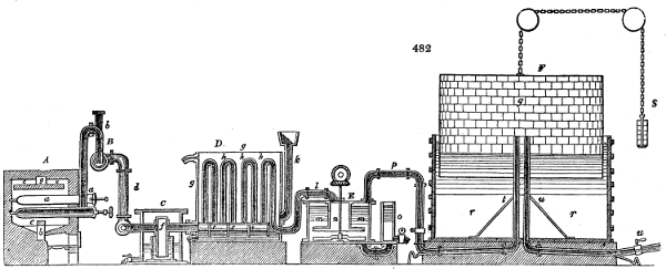
Fig. 482 enlarged (201 kB)
A is the furnace with its set of cylindrical or elliptical retorts, five in number. From each of these retorts, a tube b proceeds perpendicularly upwards, and then by a curve or saddle-tube, it turns downwards, where it enters a long horizontal cylinder under B, shut at each end with a screw cap, and descends to beneath its middle, so as to dip about an inch into the water contained in it. From one end of this cylinder the tube d passes downwards, to connect itself with a horizontal tube which enters into the tar pit or cistern C, by means of the vertical branch f. This branch reaches to near the bottom of the cylindrical vessel, which sits on the sole of the tar cistern. From the other side of the vertical branch f, the main pipe proceeds to the condenser D, and thence by the pipe l, into the purifier E; from which the gas is immediately transmitted by the pipe p into the gasometer F.
The operation proceeds in the following way:—As soon as gas begins to be disengaged from the ignited retort, tar and ammoniacal liquor are deposited in the cylindrical receiver B, and fill it up till the superfluity runs over by the pipe d, the level being constantly preserved at the line shown in the figure. By the same tarry liquid, the orifices of the several pipes b, issuing from the retorts, are closed; whereby the gas in the pipe d has its communication cut off with the gas in the retorts. Hence if one of the retorts be opened and emptied, it remains shut off from the rest of the apparatus. This insulation of the several retorts is the function of the pipe under B, and therefore the recurved tube b must be dipped as far under the surface of the tarry liquid, as to be in equilibrio with the pressure of the gas upon the water in the purifier. The tube b is closed at top with a screw cap, which can be taken off at pleasure, to permit the interior to be cleansed.
Both by the overflow from the receiver-pipe B, and by subsequent condensation in the tube d, tar and ammoniacal liquor collect progressively in the cistern or pit under C, by which mingled liquids the lower orifice of the vertical tube f is closed, so that the gas cannot escape into the empty space of this cistern. These liquids flow over the edges of the inner vessel when it is full, and may, from time to time, be drawn off by the stopcock at the bottom of the cistern.
Though the gas has, in its progress hitherto, deposited a good deal of its tarry and ammoniacal vapours, yet, in consequence of its high temperature, it still retains a considerable portion of them, which must be immediately abstracted, otherwise the tar would pollute the lime in the vessel E, and interfere with its purification. On this account the gas should, at this period of the process, be cooled as much as possible, in order to condense these vapours, and to favour the action of the lime in the purifier E, upon the sulphuretted hydrogen, which is more energetic the lower the temperature of the gas. The coal gas passes, therefore, from the tube f into the tube h of the condenser D, which is placed in an iron chest g filled with water, and it deposits more tar and ammoniacal liquor in the under part of the cistern at t, t. When these liquids have risen to a certain level, they overflow into the tar-pit, as shown in the figure, to be drawn off by the stopcock as occasion may require.
The refrigerated gas is now conducted into the purifier E, which is filled with milk of lime, made by mixing one part of slaked lime with 25 parts of water. The gas, as it enters by the pipe l, depresses the water in the wide cylinder n, thence passes under the perforated disc in the under part of that cylinder, and rising up through innumerable small holes is distributed throughout the lime liquid in the vessel m. By contact with the lime on this extended surface, the gas is stripped of its sulphuretted hydrogen and carbonic acid, which are condensed into the hydro-sulphuret and carbonate of lime; it now enters the gasometer F in a purified state, through the pipe p t, and occupies the space q. The gasometer, pressing with a small unbalanced force over the counterweight s, expels it through the main u u, in communication with the pipes of distribution through the buildings or streets to be illuminated.
The parts A B C D E and F, of which this apparatus consists, are essential constituents of every good coal-gas work. Their construction rests upon peculiar principles, is susceptible of certain modifications, and therefore deserves to be considered in detail.
The Retorts.—These are generally made of cast iron, though they have occasionally been made of baked clay, like common earthenware retorts. The original form was a cylinder, which was changed to an ellipse, with the long axis in a horizontal direction, then into the shape of the letter D with the straight line undermost, and lastly into a semi-cylinder, with its horizontal diameter 22 inches, and its vertical varying from 9 to 12. The kidney form was at one time preferred, but it has been little used of late.
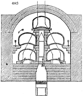
The form of retort represented in fig. 483. has been found to yield the largest quantity of good gas in the shortest time, and with the least quantity of firing. The length is 71⁄2, and the transverse area, from one foot to a foot and a half square. The arrows show the direction of the flame and draught in this excellent bench of retorts, as mounted by Messrs. Barlow.
The charge of coals is most conveniently introduced in a tray of sheet iron, made somewhat like a grocer’s scoop, adapted to the size of the retort, which is pushed home to its further end, inverted so as to turn out the contents, and then immediately withdrawn.
The duration of the process, or the time of completing a distillation, depends upon the nature of the coal and the form of the retort. With cylindrical retorts it cannot be finished in less than 6 hours, but with elliptical and semi-cylindrical retorts, it may be completed in 4 or 5 hours. If the distillation be continued in the former for 8 hours, and in the latter for 6, gas will continue to be obtained, but during the latter period of the operation, of indifferent quality.
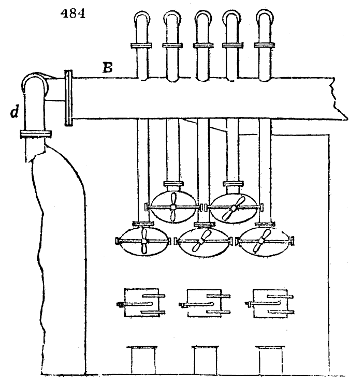
The Receiver.—If the furnace contains only 2 or 3 retorts, a simple cylindrical vessel standing on the ground half filled with water, may serve as a receiver; into which the tube from the retort may be plunged. It should be provided with an overflow pipe for the tar and ammoniacal liquor. For a range of several retorts, a long horizontal cylinder is preferable, like that represented at B in fig. 484. Its diameter is from 10 to 15 inches. This cylinder may be so constructed as to separate the tar from the ammoniacal liquor, by means of a syphon attached to one of its ends.
The Condenser.—The condenser, represented in fig. 482., consists of a square chest, g, made of wrought iron plates open at top, but having its bottom pierced with a row of holes, to receive a series of tubes. To these holes the upright four-inch tubes h h are secured by flanges and screws, and they are connected in pairs at top by the curved or saddle tubes. The said bottom forms the cover of the chest t, t, which is divided by vertical iron partitions, into half as many compartments as there are tubes.
These partition plates are left open at bottom, so as to place the liquids of each compartment in communication. Thereby the gas passes up and down the series of tubes, in proceeding from one compartment to another. The condensed liquids descend into the box t, t, and flow over into the tar cistern, when they rise above the level t, t. The tar may be drawn off from time to time by the stopcock. Through the tube k, cold water flows into the condenser chest, and the warm water passes away by a pipe at its upper edge.
The extent of surface which the gas requires for its refrigeration before it is admitted into the washing-lime apparatus, depends upon the temperature of the milk of lime, and the quantity of gas generated in a certain time.
It may be assumed as a determination sufficiently exact, that 10 square feet of surface of the condenser can cool a cubic foot of gas per minute to the temperature of the cooling water. For example, suppose a furnace or arch with 5 retorts of 150 pounds of coal each, to produce in 5 hours 3000 cubic feet of gas, or 10 cubic feet per minute, there would be required, for the cooling surface of the condenser, 100 square feet = 10 × 10. Suppose 100,000 cubic feet of gas to be produced in 24 hours, for which 8 or 9 such arches must be employed, the condensing surface must contain from 800 to 900 square feet.
The Purifier.—The apparatus represented in the preceding figure is composed of a cylindrical iron vessel, with an air-tight cover screwed upon it, through which the cylinder n is also fixed air-tight. The bottom of this cylinder spreads out like the brim of a hat, forming a horizontal circular partition, which is pierced with holes. Through a stuffing box, in the cover of this interior cylinder, the vertical axis of the agitator passes, which is turned by wheel and pinion work, in order to stir up the lime from the bottom of the water in the purifier. The vessel o serves for introducing fresh milk of lime, as also for letting it off by a stopcock when it has become too foul for further use.
The quantity of lime should be proportioned to the quantity of sulphuretted hydrogen and carbonic acid contained in the gas. Supposing that in good coal gas there is 5 per cent. of these gases, about one pound and a half of lime will be requisite for every hundred cubic feet of coal gas generated, which amounts to nearly one-sixteenth of the weight of coal subjected to decomposition. This quantity of lime mixed with the proper quantity of water will form about a cubic foot of milk of lime. Consequently, the capacity of the purifier, that is, of the interior space filled with liquid, may be taken at four-sevenths of a cubic foot for every hundred cubic feet of gas passing through it in one operation; or for 175 cubic feet of gas, one cubic foot of liquor. After every operation, that is, after every five or six hours, the purifier must be filled afresh. Suppose that in the course of one operation 20,000 cubic feet of gas pass through the machine, this should be able to contain 20,000175 = 114 cubic feet of milk of lime; whence its diameter should be seven feet, and the height of the liquid three feet. If the capacity of the vessel be less, the lime milk must be more frequently changed.
In some of the large gas works of London the purifier has the following construction, whereby an uninterrupted influx and efflux of milk of lime takes place. Three single purifiers are so connected together, that the second vessel stands higher than the first, and the third than the second; so that the discharge tube of the superior vessel, placed somewhat below its cover, enters into the upper part of the next lower vessel; consequently, should the milk of lime in the third and uppermost vessel rise above its ordinary level, it will flow over into the second, and thence in the same way into the first; from which it is let off by the eduction pipe. A tube introduces the gas from the condenser into the first vessel, another tube does the same thing for the second vessel, &c., and the tube of the third vessel conducts the gas into the gasometer. Into the third vessel, milk of lime is constantly made to flow from a cistern upon a higher level. By this arrangement, the gas passing through the several vessels in proportion as it is purified, comes progressively into contact with purer milk of lime, whereby its purification becomes more complete. The agitator c, provided with two stirring paddles, is kept in continual rotation. The pressure which the gas has here to overcome is naturally three times as great as with a single purifier of like depth.
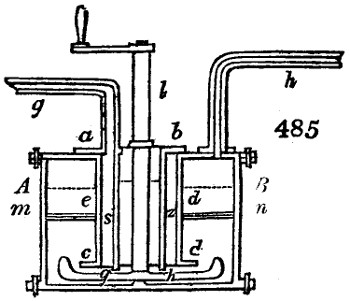
Fig. 485. is a simple form of purifier, which has been found to answer well in practice. Through the cover of the vessel A B, the wide cylinder e d is inserted, having its lower end pierced with numerous holes. Concentric with that cylinder is the narrower one s z, bound above with the flange a b, but open at top and bottom. The under edge g h of this cylinder descends a few inches below the end c d of the outer one. About the middle of the vessel the perforated shelf m n is placed. The shaft of the agitator l, passes through a stuffing box upon the top of the vessel. The gas-pipe g, proceeding from the condenser, enters through the flange a b in the outer cylinder, while the gas-pipe h goes from the cover to the gasometer. A stopcock upon the side, whose orifice of discharge is somewhat higher than the under edge of the outer cylinder, serves to draw off the milk of lime. As the gas enters through the pipe g into the space between the two cylinders, it displaces the liquor till it arrives at the holes in the under edge of the outer cylinder, through which, as well as under the edge, it flows, and then passes up through the apertures of the shelf m n into the milk of lime chamber; the level of which is shown by the dotted line. The stirrer, l, should be turned by wheel work, though it is here shown as put in motion by a winch handle.
In order to judge of the degree of purity of the gas after its transmission through the lime machine, a slender syphon tube provided with a stopcock may have the one end inserted in its cover, and the other dipped into a vessel containing a solution of acetate of lead. Whenever the solution has been rendered turbid by the precipitation of sulphuret of lead, it should be renewed. The saturated and fetid milk of lime is evaporated in oblong cast-iron troughs placed in the ash-pit of the furnaces, and the dried lime is partly employed for luting the apparatus, and partly disposed of for a mortar or manure.
By this purifier, and others of similar construction, the gas in the preceding parts of the apparatus, as in the retorts and the condenser, suffers a pressure equal to a column of water about two feet high; and in the last described purifier even a greater pressure. This pressure is not disadvantageous, but is of use in two respects; 1. it shows by a brisk jet of gas when the apparatus is not air-tight, and it prevents common air from entering into the retorts; 2. this compression of the gas favours the condensation of the tar and ammoniacal liquor. The effect of such a degree of pressure in expanding the metal of the ignited retorts is quite inconsiderable, and may be neglected. Two contrivances have, however, been proposed for taking off this pressure in the purifier.
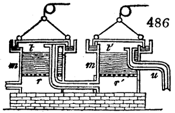
In fig. 486., m m are two similar vessels of a round or rectangular form, furnished at their upper border with a groove filled with water, into which the under edge of the cover fits, so as to make the vessel air-tight. The cover is suspended by a cord or chain, which goes over a pulley, and may be raised or lowered at pleasure. The vessels themselves have perforated bottoms, r r′, covered with wetted moss or hay sprinkled over with slaked and sifted quicklime. The gas passes through the loosely compacted matter of the first vessel, by entering between its two bottoms, rises into the upper space t, thence it proceeds to the second vessel, and, lastly, through the pipe u into the gasometer. This method, however, requires twice as much lime as the former, without increasing the purity of the gas.
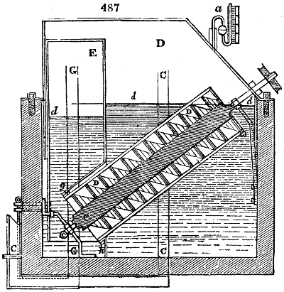
The second method consists in compressing the gas by the action of an Archimedes screw, to such a degree, before it is admitted into the purifier, as that it may overcome the pressure of the column of water in that vessel. Fig. 487. exhibits this apparatus in section. D D is the Archimedes worm, the axis of which revolves at bottom upon the gudgeon e; it possesses a three-fold spiral, and is turned in the opposite direction to that in which it scoops the water. The cistern which contains it has an air-tight cover. The gas to be purified passes through the pipe C into the space D, over the water level d; the upper cells of the worm, scoop in the gas at this point, and carry it downwards, where it enters at g into the cavity E of a second cistern. In order that the gas, after it escapes from the bottom of the worm, may not partially return through g into the cavity D, an annular plate g h is attached to its under edge, so as to turn over it. The compressed gas is conducted from the cavity E through the pipe G into the purifying machine; a is a manometer, to indicate the elastic tension of the gas in D. On the top of the worm a mechanism is fitted for keeping it in constant rotation.
A perfect purification of light-gas from sulphuretted hydrogen, either by milk of lime or a solution of the green sulphate of iron, is attended with some difficulty, when carried so far as to cause no precipitation of sulphuret in acetate of lead, because such a degree of washing is required as is apt to diminish its illuminating power, by abstracting the vapour of the rich oily hydrocarburet which it contains. Moreover, the coal gas obtained towards the end of the distillation contains some sulphuret of carbon, which affords sulphurous acid on being burned, and can be removed by no easy method hitherto known. The lime in the purifier disengages from the carbonate and hydrosulphuret of ammonia carried over with the gas, especially when it has been imperfectly cooled in the condenser, a portion of ammoniacal gas, which, however, is not injurious to its illuminating power. The best agent for purifying gas would be the pyrolignite of lead, were it not rather expensive, because it would save the trouble of stirring, and require a smaller and simpler apparatus.
The Gasometer.—The gasometer serves not merely as a magazine for receiving the gas when it is purified, and keeping it in store for use, but also for communicating to the gas in the act of burning such an uniform pressure as may secure a steady unflickering flame. It consists of two essential parts; 1. of an under cistern, open at top and filled with water; and 2. of the upper floating cylinder or chest, which is a similar cistern inverted, and of somewhat smaller dimensions, called the gas-holder: see F, fig. 482. The best form of this vessel is the round or cylindrical; both because under equal capacity it requires least surface of metal, and it is least liable to be warped by its own weight or accidents. Since a cylindrical body has the greatest capacity with a given surface when its height is equal to its semi-diameter, its dimensions ought to be such that when elevated to the highest point in the water, the height may be equal to the radius of the base. For example, let the capacity of the gas-holder in cubic feet be k, the semi-diameter of its base be x, the height out of the water be h; h is = x = ∛k3·14. This height may be increased by one or two feet, according to its magnitude, to prevent the chance of any gas escaping beneath its under edge, when it is raised to its highest elevation in the water.
The size of the gasometer should be proportional to the quantity of gas to be consumed in a certain time. If 120,000 cubic feet be required, for instance, in 10 hours for street illumination, and if the gas retorts be charged four times in 24 hours, 30,000 cubic feet of gas will be generated in 6 hours. Hence the gasometer should have a capacity of at least 70,000 cubic feet, supposing the remaining 50,000 cubic feet to be produced during the period of consumption. If the gasometer has a smaller capacity, it must be supplied from a greater number of retorts during the lighting period, which is not advantageous, as the first heating of the supernumerary retorts is wasteful of fuel. Some engineers consider that a capacity of 30,000 cubic feet is the largest which can with propriety be given to a gasometer; in which case, they make its diameter 42 feet, and its height 23. When the dimensions are greater, the sheet iron must be thicker and more expensive; and the hollow cylinder must be fortified by strong internal cross braces.
The water cistern is usually constructed in this country with cast-iron plates bolted together, and made tight with rust-cement.
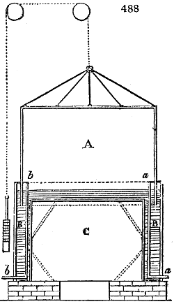
In cases where the weight of water required to fill such a cistern might be inconvenient to sustain, it may be made in the form represented in fig. 488.; which, however, will cost nearly twice as much. Parallel with the side of the cistern, a second cylinder C, of the same shape but somewhat smaller, is fixed in an inverted position to the bottom of the first, so as to leave an annular space B B between them, which is filled with water, and in which the floating gasometer A plays up and down. The water must stand above the cover of the inverted cylinder. a and b are the pipes for leading the gas in and out. Through an opening in the masonry upon which the gasometer apparatus rests, the space C may be entered, in order to make any requisite repairs.
The water cistern may also be sunk in the ground, and the sides made tight with hydraulic mortar, as is shown in fig. 489., and to make it answer with less water, a concentric cylindrical mass of masonry may be built at a distance of 2 or 3 inches within it.
Every large gasometer must be strengthened interiorly with cross iron rods, to stiffen both its top and bottom. The top is supported by rods stretching obliquely down to the sides, and to the under edge an iron ring is attached, consisting of curved cast-iron bars bolted together; with which the oblique rods are connected by perpendicular ones. Other vertical rods stretch directly from the top to the bottom edge. Upon the periphery of the top, at the end of the rods, several rings are made fast, to which the gas-holder is suspended, by means of a common chain which runs over a pulley at the centre. Upon the other end of the chain there is a counterpoise, which takes off the greater part of the weight of the gas-holder, leaving only so much as is requisite for the expulsion of the gas. The inner and outer surfaces of the gas-holder should be a few times rubbed over with hot tar, at a few days’ interval between each application. The pulley must be made fast to a strong frame.
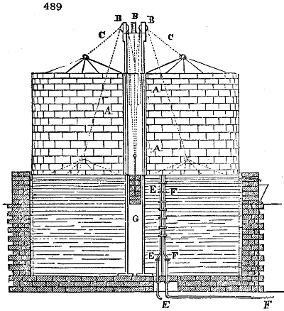
If the water cistern be formed with masonry, the suspension of the gas-holder may be made in the following way. A A, fig. 489., is a hollow cylinder of cast iron, standing up through the middle of the gasometer, and which is provided at either end with another small hollow cylinder G, open at both ends and passing through the top, with its axis placed in the axis of the gas-holder. In the hollow cylinder G, the counterweight moves up and down, with its chain passing over the three pulleys B, B, B, as shown in fig. 489. E F are the gas pipes made fast to a vertical iron rod. Should the gasometer be made to work without a counterweight, as we shall presently see, the central cylinder A A, serves as a vertical guide.
In proportion as the gas-holder sinks in the water of the cistern, it loses so much of its weight, as is equal to the weight of the water displaced by the sides of the sinking vessel; so that the gas-holder when entirely immersed, exercises the least pressure upon the gas, and when entirely out of the water, it exercises the greatest pressure. In order to counteract this inequality of pressure, which would occasion an unequal velocity in the efflux of the gas, and of course an unequal intensity of light in its flame, the weight of the chain upon which the gas-holder hangs is so adjusted as to be equal, throughout the length of its motion, to one half of the weight which the gas-holder loses by immersion. In this case, the weight which it loses by sinking into the water, is replaced by the portion of the chain which passing the pulley, and hanging over, balances so much of the chain upon the side of the counterweight; and the weight which it gains by rising out of the water, is counterpoised by the links of the chain which passing over the pulley, add to the amount of the counterweight. The pressure which the gas-holder exercises upon the gas, or that with which it forces it through the first main pipe, is usually so regulated as to sustain a column of from one to two inches of water; so that the water will stand in the cistern from one to two inches higher within, than without the gas-holder. The following computation will place these particulars in a clear light.
Let the semi-diameter of the gas-holder, equal to the vertical extent of its motion into and out of the water, = x; let the weight of a foot square of the side of the gas-holder, including that of the strengthening bars and ring, which remain plunged under the water, be = p; then
1. the weight of the gas-holder in its highest position = 3 p π x2;
2. the weight of the sides of the gas-holder which play in the water = 2 p π x2;
3. the cubic contents of the immersed portion of the gas-holder = 2 p π x2400;
4. its loss of weight in water = 112400 p π x2;
5. the weight of the gas-holder in its lowest position = p π x2 (3 - 112400) = 2·72 p π x2;
6. the weight of n inches, height of water = 5612 n π x2;
7. the amount of the counterweight = π x2 (3 p - 56 n12);
8. the weight of the chain for the length x = 112800 p π x.
If we reduce the weight of the gas-holder in its highest and lowest positions to the height of a stratum of water equal to the surface of its top, this height is that of the column of water which would press the gas within the gasometer, were no counterweight employed; it consists as follows;—
9. for the highest position = 3 p56;
10. for the lowest = 2·72 p50;
For the case, when the height of the gas-holder is different from its semi-diameter, let this height = m x; then the height of the water level is
11. for the highest position = p (1 + 2 m56);
12. for the lowest = p (1 + 1·72 m6);
13. the counterweight = π x2 (p (1 + 2m) - 56 n12);
14. the weight of the equalizing chain = 112800 p π m x2.
For example, let the diameter of the gas-holder be 30 feet, the height 15 (the contents in cubic feet will be 10,597), p = 4 pounds; then the counterweight for a height of an inch and a half of water pressure = 3532 pounds; the weight of the chain for a length of 15 feet = 395 pounds. Were no counterweight employed, so that the gas-holder pressed with its whole weight upon the gas, then the height of the equivalent column of water in its highest position = 2·56 inches; and in its lowest, 2·33. The counterweight may hence be lessened at pleasure, if the height of the pressing water-column n be increased. The weight of the equalising or compensating portion of the chain remains the same. When n = 2 inches, for instance, the counterweight = 1886 pounds.
The velocity with which the gas passes along the mains for supplying the various jets of light, may be further regulated by opening the main-cock or slide-valve in a greater or less degree.
Gasometers whose height is greater than their semi-diameter, are not only more costly in the construction, but require heavier counterweights and equilibration chains.
The above estimate is made on the supposition of the gas in the gas-holder being of the same specific gravity as the atmospherical air, which would be nearly true with regard to oil gas under the ordinary pressure. But coal gas, whose specific gravity may be taken on an average at about 0·5, exercises a buoyancy upon the top of the gas-holder, which of course diminishes its absolute weight. Supposing the cubic foot of gas to be = 0·0364 pounds, the buoyancy will be = 0·0364 π x3 pounds; a quantity which deserves to be taken into account for large gasometers. Hence,
15. the weight of the gas-holder in its highest position = 3 p π x2 - 0·1143 x3;
16. the counterweight = π x2 (3 p - 56 n12) - 0·1143 x2;
17. The weight of the chain for the length x, = 112800 p π x2 0·1143 x32;
18. The height of the water pressure for the highest position, without the counterweight = 3 p π - 0·1143 x56 π;
19. the same for the lowest position = 2·72 p56 in feet.
The preceding values of p and x, are,
(16) = 3147; (17) = 203; (18) = 2·44 inches; (19) = 2·33 inches.
The water columns in the highest and lowest situations of the gas-holder here differ about 0·1 of an inch, and this difference becomes still less when p has a smaller value, for example, 3 pounds, or when the diameter of the gas-holder is still greater.
It would thus appear that for coal-gas gasometers, in which the height of the gas-holder does not exceed its semi-diameter, and especially when it has a considerable size, neither a compensation chain nor a counterweight is necessary. The only thing requisite, is to preserve the vertical motion of the gas-holder by a sufficient number of guide rods or pillars, placed either within the water cistern, or round about it. Should the pressure of the gas in the pipe proceeding from the gasometer, be less than in the gasometer itself, this may be regulated by the main valve, or by water valves of various kinds. Or a small intermediate regulating gasometer may be introduced between the great gas-holder, and the main pipe of distribution. With a diameter of 61 feet in the gas-holder, the pressure in the highest and lowest positions is the same.
The gasometers employed in storing up gas until required for use, occupy, upon the old plan, much space, and are attended with considerable expense in erecting. The water tank, whether sunk in the ground, or raised, must be of equal dimensions with the gasometer, both in breadth and depth. The improved construction which we are about to describe, affords a means of reducing the depth of the tank, dispensing with the bridge of suspension, and of increasing at pleasure the capacity of the gasometer, upon a given base; thus rendering a small apparatus capable, if required, of holding a large quantity of gas, the first cost of which will be considerably less than even a small gasometer constructed upon the ordinary plan.
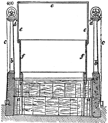
Mr. Tait, of Mile-End Road, the inventor, has, we believe, been for some years connected with gas establishments, and is therefore fully aware of the practical defects or advantages of the different constructions of gasometers now in use. Fig. 490. is a section of Mr. Tait’s improved contrivance; a a is the tank, occupied with water, b b two iron columns, with pulley-wheels on the top, c c, chains attached to a ring of iron, d d, extending round the gasometer, which chains pass over the pulley-wheels, and are loaded at their extremities, for the purpose of balancing the weight of the materials of which the gasometer is composed.
The gasometer is formed by 2 or 3 cylinders, sliding one within the other, like the tubes of a telescope; e, e, e, is the first or outer cylinder, closed at the top, and having the ring of iron d, passing round it, by which the whole is suspended; f f, is the second cylinder, sliding freely within the first, and there may be a third and fourth within these if necessary.
When there is no gas in the apparatus, all the cylinders are slidden down, and remain one within the other immersed in the tank of water; but when the gas rises through the water pressing against the top of the gasometer, its buoyancy causes the cylinder e to ascend. Round the lower edge of this cylinder a groove is formed by the turning in of the plate of iron, and as it rises, the edge takes hold of the top rim of the cylinder f, which is overlapped for that purpose. The groove at the bottom of the cylinder fills itself with water as it ascends, and by the rim of the second cylinder falling into it, an air-tight hydraulic joint is produced.
Thus, several cylinders may be adapted to act in a small tank of water, by sliding one within the other, with lapped edges forming hydraulic joints, and by supporting the apparatus in the way shown, the centre of gravity will always be below the points of suspension. A gasometer may be made upon this plan of any diameter, as there will be no need of frame work, or a bridge to support it; and the increasing weight of the apparatus, as the cylinders are raised one after the other, may be counterpoised by loading the ends of the chains c c.
The water in the gasometer need not be renewed; but merely so much of it as evaporates or leaks out, is to be replaced. Indeed the surface of the water in the cistern gets covered with a stratum of coal oil, a few inches deep, which prevents its evaporation, and allows the gas to be saturated with this volatile substance, so as to increase its illuminating powers.
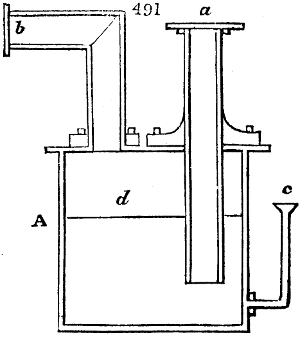
The gasometer may be separated from the purifier by an intermediate vessel, such as is represented fig. 491., with which the two gas pipes are connected. A is the cylindrical vessel of cast iron, a, the end of the gas pipe which comes from the purifier, immersed a few inches deep into the liquid with which the vessel is about two-thirds filled; b is the gas-pipe which leads into the gasometer, c is a perpendicular tube, placed over the bottom of the vessel, and reaching to within one-third of the top, through which the liquid is introduced into the vessel, and through which it escapes when it overflows the level d. In this tube the liquid stands towards the inner level higher, in proportion to the pressure of the gas in the gasometer. The fluid which is condensed in the gas pipe, b, and in its prolongation from the gasometer, runs off into the vessel A; and therefore the latter must be laid so low that the said tube may have the requisite declivity. A straight stop-cock may also be attached to the side over the bottom, to draw off any sediment.
II. Application of Light-Gas.
1. Distribution of the pipes.—The pressure by which the motion of the gas is maintained in the pipes, corresponds to a certain height of water in the cistern of the gasometer. From the magnitude of this pressure, and the quantity of gas which in a given time, as an hour, must be transmitted through a certain length of pipes, depends the width or the diameter that they should have, in order that the motion may not be retarded by the friction which the gas, like all other fluids, experiences in tubes, and thereby the gas might be prevented from issuing with the velocity required for the jets of flame. The velocity of the gas in the main pipe increases in the ratio of the square root of the pressing column of water upon the gasometer, and therefore by increasing this pressure, the gas may be forced more rapidly along the remoter and smaller ramifications of the pipes. Thus it happens, however, that the gas will be discharged from the orifices near the gasometer, with superfluous velocity. It is therefore advisable to lay the pipes in such a manner, that in every point of their length, the velocity of discharge may be nearly equal. This may be nearly effected as follows;—
From experiment it appears that the magnitude of the friction, or the resistance which the air suffers in moving along the pipes, under a like primary pressure, that is for equal initial velocity, varies with the square root of the length. The volume of gas discharged from the end of a pipe, is directly proportional to the square of its diameter, and inversely as the square root of its length; or, calling the length L, the diameter D, the cubic feet of gas discharged in an hour k; then k = D2√L. Experience likewise shows, that for a pipe 250 feet long, which transmits in an hour 200 cubic feet of gas, one inch is a sufficient diameter.
Consequently, 200 : k ∷ 1144 √250 : D2√L; and D = √k √L455,000
From this formula the following table of proportions is calculated.
Number of cubic feet per hour. Length of pipe, in feet. Diameter, in inches.
50 100 0 ·40
250 200 1 ·00
500 600 1 ·97
700 1000 2 ·65
1000 1000 3 ·16
1500 1000 3 ·87
2000 1000 4 ·47
2000 2000 5 ·32
2000 4000 6 ·33
2000 6000 7 ·00
6000 1000 7 ·75
6000 2000 9 ·21
8000 1000 8 ·95
8000 2000 16 ·65
These dimensions are applicable to the case where the body of gas is transmitted through pipes without being let off in its way by burners, that is, to the mains which conduct the gas to the places where it is to be used. If the main sends off branches for burners, then for the same length the diameter may be reduced, or for like diameter the length may be greater. For example, if a pipe of 5·32 inches, which transmits 2000 cubic feet through a length of 2000 feet, gives off, in this space, 1000 cubic feet of gas; then the remainder of the pipe, having the same diameter, can continue to transmit the gas through a length of 2450 feet = (450,000k)2, with undiminished pressure for the purposes of lighting. Inversely, the diameter should be progressively reduced in proportion to the number of jets sent off in the length of the pipe.
Suppose for instance, the gasometer to discharge 2000 cubic feet per hour, and the last point of the jets to be at a distance of 4000 feet. Suppose also that from the gasometer to the first point of lighting, the gas proceeds through 1000 feet of close pipe, the diameter of the pipe will be here 4·47 inches; in the second 1000 feet of length, suppose the pipe to give off, at equal distances, 1000 cubic feet of gas, the diameter in this length (calculated at 1500 cubic feet for 1000 feet long) = 3·87 inches; in the third extent of 1000 feet, 600 cubic feet of gas will be given off, and the diameter (reckoning 700 cubic feet for 1000 feet long) will be 2·65 inches; in the fourth and last space (for 200 cubic feet in 1000 feet long) the pipe has a diameter of only an inch and a half, for which, in practice, a two-inch cast iron pipe is substituted; this being the smallest used in mains, into which branch pipes can be conveniently inserted.
The same relations hold with regard to branch pipes through which the gas is transmitted into buildings and other places to be illuminated. If such pipes make frequent angular turnings, whereby they retard the motion of the gas, they must be a third or a half larger in diameter. The smallest tubes of distribution are never less than one fourth of an inch in the bore.
Where, from one central gas work, a very great quantity of light is required in particular localities, there ought to be placed near these spots gasometers of distribution, which, being filled during the slack hours of the day, are ready to supply the burners at night, without making any considerable demand upon the original main pipe. Suppose the first main be required to supply 8000 cubic feet in the hour, for an illumination of 8 hours, at the distance of 2000 feet, a pipe 102⁄3 inches in diameter would be necessary; but if two or three gasometers of distribution, or station gasometers be had recourse to, into which the gas during the course of 24 hours would flow through the same distance continuously from the central gas works, the quantity required per hour from them would be only one third of 8000, = 2666·6 cubic feet; consequently the diameter for such a pipe is only 6·15 inches.
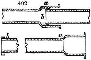
All the principal as well as branch pipes, whose interior diameter exceeds an inch and a half, are made of cast iron from 6 to 8 feet long, with elbow pipes cast in them where it is necessary. These pipe lengths are shown in fig. 492., having at one end a wide socket a, and at the other a nozzle b, which fits the former. After inserting the one in the other in their proper horizontal position, a coil of hemp soaked with tar is driven home at the junction; then a luting of clay is applied at the mouth, within which a ring of lead is cast into the socket, which is driven tight home with a mallet and blunt chisel.
The pipes should be proved by a force pump before being received into the gas works; two or three lengths of them should be joined before laying them down, and they should be placed at least two feet below the surface, to prevent their being affected by changes of temperature, which would loosen the joints. The tubes for internal distribution, when of small size are made of lead, copper, wrought iron, or tin.
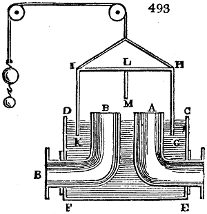
Instead of a stopcock for letting off the gas in regulated quantities from the gasometer, a peculiarly formed water or mercurial valve is usually employed. Fig. 493. shows the mode of construction for a water trap or lute, and is, in fact, merely a gasometer in miniature. C D E F is a square cast iron vessel, in the one side of which a pipe A is placed in communication with the gasometer, and in the other, one with the main B. The movable cover or lid H G I K has a partition, L M, in its middle. If this cover be raised by its counterweight, the gas can pass without impediment from A to B; but if the counterweight be diminished so as to let the partition plate L M sink into the water, the communication of the two pipes is thereby interrupted. In this case the water-level stands in the compartment A so much lower than outside of it, and in the compartment B, as is equivalent to the pressure in the gasometer; therefore the pipes A and B must project thus far above the water. In order to keep the water always at the same height, and to prevent it from flowing into the mouths of these pipes, the rim C D of the outer vessel stands somewhat lower than the orifices A B; and thence the vessel may be kept always full of water.
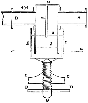
If a quicksilver valve be preferred, it may be constructed as shown in fig. 494. A B are the terminations of the two gas pipes, which are made fast in the rectangular iron vessel M. E is an iron vessel of the same form, which is filled with quicksilver up to the level a, and which, by means of the screw G, which presses against its bottom, and works in the fixed female screw C C, may be moved up or down, so that the vessel M may be immersed more or less into the quicksilver. The vessel M is furnished with a vertical partition m; the passage of the gas from A to B is therefore obstructed when this partition dips into the quicksilver, and from the gradual depression of the vessel E by its screw, the interval between the quicksilver and the lower edge of the partition, through which the gas must enter, may be enlarged at pleasure, whereby the pressure of the gas in B may be regulated to any degree. The transverse section of that interval is equal to the area of the pipe or rather greater; the breadth of the vessel M from A to B amounts to the double of that space, and its length to the mere diameter of A or B. The greatest height to which the partition m can rise out of the quicksilver, is also equal to the above diameter, and in this case the line a comes to the place of b. The vertical movement of the outer vessel E, is secured by a rectangular rim or hoop which surrounds it, and is made fast to the upper part of the vessel M, within which guide it moves up and down. Instead of the lever D D, an index with a graduated plate may be employed to turn the screw, and to indicate exactly the magnitude in the opening of the valve.
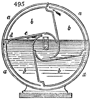
In order to measure the quantity of gas which passes through a pipe for lighting a factory, theatre, &c., the gas-meter is employed, of whose construction a sufficiently precise idea may be formed from the consideration of fig. 495., which shows the instrument in a section perpendicular to its axis.
Within the cylindrical case a, there is a shorter cylinder b b, shut at both ends, and movable round an axis, which is divided into four compartments, that communicate by the opening d, with the interval between this cylinder and the outer case. The mode in which this cylinder turns round its axis is as follows:—The end of the tube c, which is made fast to the side of the case, and by which the gas enters, carries a pivot or gudgeon, upon which the centre of its prop turns; the other end of the axis runs in the cover, which here forms the side of a superior open vessel, in which, upon the same axis, there is a toothed wheel. The vessel is so far filled with water, that the tube c just rises above it, which position is secured by the level of the side vessel. When the gas enters through the tube c, by its pressure upon the partition e, (fig. 495.) it turns the cylinder from right to left upon its axis, till the exterior opening d rises above the water, and the gas expands itself in the exterior space, whence it passes off through a tube at top. At every revolution a certain volume of gas thus goes through the cylinder, proportional to its known capacity. The wheel on the axis works in other toothed wheels, whence, by means of an index upon a graduated disc or dial, placed at top or in front of the gas-meter, the number of cubic feet of gas, which pass through this apparatus in a given time, is registered.
B. Employment of the gas for lighting.—The illuminating power of different gases burned in the same circumstances, is proportional, generally speaking, to their specific gravity, as this is to the quantity of carbon they hold in combination. The following table exhibits the different qualities of gases in respect to illumination.
Density or specific gravity. Proportion of light afforded by coal gas to oil gas.
Coal gas. Oil gas.
0 ·659 0 ·818 100 : 140
0 ·578 0 ·910 100 : 225
0 ·605 1 ·110 100 : 250
0 ·407 0 ·940 100 : 354
0 ·429 0 ·965 100 : 356
0 ·508 1 ·175 100 : 310
Mean 0 ·529 0 ·96 100 : 272
In the last three proportions, the coal gas was produced from coals of middle quality; in the first three proportions from coals of good quality; and therefore the middle proportion of 100 to 270 may be taken to represent the fair average upon the great scale. On comparing the gas from bad coals, with good oil gas, the proportion may become 100 to 300. Nay, coal gas of specific gravity 0·4, compared to oil gas of 1·1, gives the proportion of 1 to 4. A mould tallow candle, of 6 in the pound, burning for an hour, is equivalent to half a cubic foot of ordinary coal gas, and to four tenths of a foot of good gas. The flame of the best argand lamp of Carcel, in which a steady supply of oil is maintained by pump-work, consuming 42 grammes = 649 grains English in an hour, and equal in light to 9·38 such candles, is equivalent to 3·75 cubic feet of coal gas per hour. The sinumbra lamp, which consumes 50 grammes = 772 grains English, of oil per hour, and gives the light of 8 of the above candles, is equivalent to the light emitted by 3·2 cubic feet of coal gas burning for an hour. A common argand lamp, equal to 4 candles, which consumes 30 grammes = 463 grains English per hour, is represented by 1·6 cubic feet of gas burning during the same time. A common lamp, with a flat wick and glass chimney, whose light is equal to 1·13 tallow candles, and which consumes 11 grammes = 169·8 grains English per hour, is represented by 0·452 of a cubic foot of gas burning for the same time.
Construction of the Burners.—The mode of burning the gas as it issues from the jets has a great influence upon the quantity and quality of its light. When carburetted hydrogen gas is transmitted through ignited porcelain tubes, it is partially decomposed with a precipitation of some of its carbon, while the resulting gas burns with a feebler flame. Coal gas, when kindled at a small orifice in a tube, undergoes a like decomposition and precipitation. Its hydrogen, with a little of its carbon, burns whenever it comes into contact with the atmospherical air, with a bluish coloured flame; but the carbonaceous part not being so accendible, takes fire only when mixed with more air; therefore at a greater distance from the beak, and with a white light from the vivid ignition of its solid particles. Upon this principle pure hydrogen gas may be made to burn with a white instead of its usual blue flame, by dusting into it particles of lamp black; or by kindling it at the extremity of a tube containing finely pulverized zinc. The metallic particles become ignited, and impart their bright light to the pale blue flame. Even platinum wire and asbestos, when placed in the flame of hydrogen gas, serve to whiten it. Hence it has been concluded, that the intensity of light which a gas is capable of affording is proportional to the quantity of solid particles which it contains, and can precipitate in the act of burning. Carbonic oxide gas burns with the feeblest light next to hydrogen, because it deposits no carbon in the act of burning. Phosphuretted hydrogen gives a brilliant light, because the phosphoric acid, into which its base is converted during the combustion, is a solid substance, capable of being ignited in the flame. Olefiant gas, as also the vapour of hydro-carbon oil, emits a more vivid light than common coal gas; for the first is composed of two measures of hydrogen and two measures of the vapour of carbon condensed into one volume; while the last contains only one measure of the vapour of carbon in the same bulk, and combined with the same proportion of hydrogen. Olefiant gas may therefore be expected to evolve a double quantity of carbon in its flame, which should emit a double light.
The illuminating power of the flame of coal gas is, on the contrary, impaired, when, by admixture with other species of gas which precipitate no carbon, its own ignited particles are diffused over a greater surface. This happens when it is mixed with hydrogen, carbonic oxide, carbonic acid, and nitrogen gases, and the diminution of the light is proportional to the dilution of the coal gas.
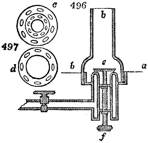
In like manner the illuminating power of coal gas is impaired, when it is consumed too rapidly to allow time for the separation and ignition of its carbonaceous matter; it burns, in this case, without decomposition, and with a feeble blue flame. 1. This occurs when the light-gas is previously mixed with atmospherical air, because the combustion is thereby accelerated throughout the interior of the flame, so as to prevent the due separation of carbon. A large admixture of atmospherical air makes the flame entirely blue. 2. When it issues, with considerable velocity, from a minute orifice, whereby the gas, by expansion, gets intimately mixed with a large proportion of atmospherical air. If the jet be vertical, the bottom part of the flame is blue, and the more so the less carbon is contained in the gas. The same thing may be observed in the flame of tallow, wax, or oil lights. The burning wick acts the part of a retort, in decomposing the fatty matter. From the lower part of the wick the gases and vapours of the fat issue with the greatest velocity, and are most freely mixed with the air; while the gases disengaged from the upper part of the wick compose the interior of the flame, and being momentarily protected from the action of the atmosphere, acquire the proper high temperature for the deposition of carbon, which is then diffused on the outer surface in an ignited state, and causes its characteristic white light. Hence with coal gas, the light increases in a certain ratio with the size of the flame as it issues from a larger orifice, because the intermixture of air becomes proportionately less. 3. If by any means too great a draught be given to the flame, its light becomes feebler by the rapidity and completeness with which the gas is burned, as when too tall a chimney is placed over an argand burner, see fig. 496. Fig. 497. c, is a view of the upper plate, upon which the glass chimney b rests. The gas issues through the smaller openings of the inner ring, and forms a hollow cylindrical flame, upon the outside as well as the inside of which the atmospherical air acts. The illuminating power of this flame may be diminished at pleasure, according as more or less air is allowed to enter through the orifices beneath. With a very full draught the light almost vanishes, leaving only a dull blue flame of great heating power, like that of the blowpipe, corresponding to the perfect combustion of the gas without precipitation of its carbon. 4. On the other hand, too small a draught of air is equally prejudicial; not merely because a portion of the carbon thus escapes unconsumed in smoke, but also because the highest illuminating power of the flame is obtained only when the precipitated charcoal is heated to whiteness, a circumstance which requires a considerable draught of air. Hence the flame of dense oil gas, or of oil in a wick, burns with a yellow light without a chimney; but when it is increased in intensity by a chimney draught, it burns with a brilliant white flame.
From the consideration of the preceding facts, it is possible to give to coal gas its highest illuminating power. The burners are either simple beaks perforated with a small round hole, or circles with a series of holes to form an argand flame, as shown in fig. 497, or two holes drilled obliquely, to make the flame cross, like a swallow’s tail, or with a slit constituting the sheet of flame called a bat’s wing, like most of the lamps in the streets of London. These burners are mounted with a stop-cock for regulating the quantity of gas.
The height of the flame, which with like pressure depends upon the size of the orifice, and with like orifice upon the amount of pressure, the latter being modified by the stop-cock, is for simple jets in the open air, as follows:—
Length of the flame 2 3 4 5 6 inches
Intensity of the light 55·6 100 150 197·8 247·4
Volume of gas consumed 60·5 101·4 126·3 143·7 182·2
Light with equal consumption 100 109 131 150 150
When the length exceeds five inches, nothing is gained in respect to light. For oil gas the same statements will serve, only on account of its superior richness in carbon, it does not bear so long a flame without smoke. Thus:—
Length of the flame 1 2 3 4 5 inches
Intensity of the light 22 63·7 96·5 141 178
Gas consumed 33·1 78·5 90 118 153
Light with equal consumption 100 122 159 181 174
The diameter of the orifice for single jets, or for several jets from the same beak, is one twenty-eighth of an inch for coal gas, and one forty-fifth for oil gas.
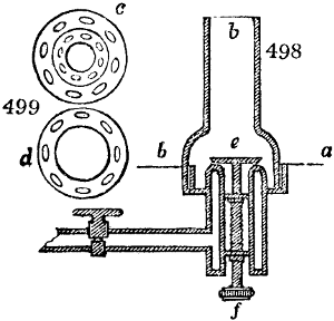
When several jets issue from the same burner, the light is improved by making all the flames unite into one. In this case the heat becomes greater, for the combined flame presents a smaller surface to be cooled, than the sum of the smaller flames. The advantage gained in this way, may be in the ratio of 3 to 2, or 50 per cent. In an argand burner, the distances of the orifices for coal gas should be from 16⁄100 to 18⁄100 of an inch, and for oil gas 12⁄100. If the argand ring has ten orifices, the diameter of the central opening should be = 4⁄10 of an inch; if 25 orifices, it should be one inch for coal gas; but for oil gas with 10 orifices, the central opening should have a diameter of half an inch, and for 20 orifices, one inch. The pin holes should be of equal size, otherwise the larger ones will cause smoke, as in an argand flame with an uneven wick. The glass chimney is not necessary to promote the combustion of an argand coal gas flame, but only to prevent it from flickering with the wind, and therefore it should be made so wide as to exercise little or no influence upon the draught. A narrow chimney is necessary merely to prevent smoke, when a very strong light, with a profusion of gas is desired. Oil gas burned in an argand beak requires a draught chimney, like a common argand lamp, on account of the large quantity of carbon to be consumed. The most suitable mode of regulating the degree of draught can be determined only by experiment, and the best construction hitherto ascertained is that represented in fig. 498. Fig. 499. exhibits the view from above, of the rim or ring c, upon which the chimney b stands, and which surrounds the perforated beak. The ring is made of open fretwork, to permit the free passage of air upwards to strike the outside of the flame. The thin annular disc d, which is laid over its fellow disc c, in the bottom of the chimney-holder, being turned a little one way or other, will allow more or less air to pass through for promoting more or less, the draught or ventilation. The draught in the central tube of the burner may be regulated by the small disc e, whose diameter is somewhat smaller than that of the ring of the burner, and which by turning the milled head f, of the screw, may be adjusted with the greatest nicety, so as to admit a greater or smaller body of air into the centre of the cylindrical flame.
In mounting gas-lights, and in estimating beforehand their illuminating effects, we must keep in mind the optical proposition, that the quantity of light is inversely as the square of the distance from the luminous body, and we must distribute the burners accordingly. When for example a gas-light placed at a distance of ten feet, is required for reading or writing to afford the same light as a candle placed at a distance of two feet; squaring each distance, we have 100 and 4; therefore 1004 = 25, shows us that 25 such lights will be necessary at the distance of 10 feet.
Concerning portable gas-light, with the means of condensing it, and carrying it from the gas works to the places where it is to be consumed, we need say nothing, as by the improvements lately made in the purification and distribution of coal-gas, the former system has been superseded.
It is well known that light gas deteriorates very considerably by keeping, especially when exposed to water over an extensive surface; but even to a certain degree over oil, or in close vessels. An oil-gas which when newly prepared has the specific gravity of 1·054, will give the light of a candle for an hour, by consuming 200 cubic inches; will, after two days, give the same light by consuming 215 cubic inches per hour; and after four days, by consuming 240 cubic inches in the like time. With coal-gas the deterioration appears to be more rapid. When newly prepared, if it affords the light of a candle with a consumption of 400 cubic inches per hour; it will not give the same light after being kept two days, except with a consumption of 430 inches; and after four days, of 460. Oil-gas three weeks old has become so much impaired in quality that 600 inches of it were required per hour to furnish the light of a candle. All light gas should be used therefore as soon as possible after it is properly purified.
Economical considerations.—The cost of gas-light depends upon so many local circumstances, that no estimate of it can be made of general application; only a few leading points may be stated. The coals required for heating the retorts used to constitute one half of the quantity required for charging the retorts themselves. When five retorts are heated by one fire, the expenditure for fuel is only one third of that when each retort has a fire. The coak which remains in the retorts constitutes about 60 per cent. of the weight of the original coal; but the volume is increased by the coaking in the proportion of 100 to 75. When the coak is used for heating the retorts, about one half of the whole is required. If we estimate the coak by its comparative heating power, it represents 65 per cent. of the coals consumed. One hundred pounds of good coal yield in distillation 10 pounds of ammoniacal liquor, from which sulphate or muriate of ammonia may be made, by saturation with sulphuric or muriatic acid, and evaporation. The liquor contains likewise some cyanide of ammonia, which may be converted into prussian blue by the addition of sulphate of iron, after saturation with muriatic acid.
Two hundred pounds of coal afford about 17 pounds of tar. This contains in 100 pounds 26 pounds of coal oil, and 48 pounds of pitch. The tar is sometimes employed as a paint to preserve wood and walls from the influence of moisture, but its disagreeable smell limits its use. The coal oil when rectified by distillation, is extensively employed for dissolving caoutchouc in making the varnish of waterproof cloth, and also for burning in a peculiar kind of lamps under the name of naphtha. Oil of turpentine however is often sold and used for this purpose, by the same name. If the coal oil be mixed with its volume of water, and the mixture be made to boil in a kettle, the mingled vapours when passed through a perforated nozzle may be kindled, and employed as a powerful means of artificial heat. The water is not decomposed, but it serves by its vapour to expand the bulk of the volatile oil, and to make it thereby come into contact with a larger volume of atmospherical air, so as to burn without smoke, under a boiler or any other vessel. The pitch may be decomposed into a light-gas.
The relative cost of light from coal gas and oil gas may be estimated as one to six, at least. Rosin gas is cheaper than oil gas. See Rosin.
I shall conclude this article with a summary of the comparative expense of different modes of illumination, and some statistical tables.
One pound of tallow will last 40 hours in six mould candles burned in succession, and costs 8d.; a gallon of oil, capable of affording the light of 15 candles, for 40 hours costs 5s., being therefore 1⁄2 of the price of mould candles, and 6⁄15 of the price of dips. The cost of wax is about 31⁄2 times that of tallow; and coal gas, as sold at the rate of 9s. for 1000 cubic feet, will be one sixth the price of mould candles; for 500 cubic inches of coal gas give a light equal to the above candle for an hour; therefore 40 × 500 = 20,000 cubic inches = 11·57 cubic feet, worth 11⁄4d., which multiplied by 6 gives 71⁄2d. the average price of mould candles per pound.
The author of the article Gas-light in the Encyclopædia Britannica, observes, in reference to the economy of this mode of illumination, that while the price of coal, in consequence of the abundant and regular supply of that article, is liable to little fluctuation, the cost of wax, tallow, and oil, on account of the more precarious nature of the sources from which they are obtained, varies exceedingly in different seasons. “Assuming that a pound of tallow candles, which last when burned in succession forty hours, costs nine-pence,” (seven-pence halfpenny is the average price), “that a gallon of oil, yielding the light of 600 candles for an hour, costs two shillings,” (five shillings is the lowest price of a gallon of such oil as a gentleman would choose to burn in his lamp), “that the expense of the light from wax is three times as great as from tallow, and that a thousand cubic feet of coal gas cost nine shillings;” he concludes the relative cost to be for the same quantity of light,—from wax, 100; tallow, 25; oil, 5; and coal-gas, 3. I conceive the estimate given above to be much nearer the truth; when referred to wax called 100, it becomes, for tallow, 28·6; oil, 14·3; coal gas, 4·76.
Gas-lighting has received a marvellous development in London. In the year 1834, the number of gas lamps in this city was 168,000, which consumed daily about 4,200,000 cubic feet of gas. For the purpose of generating this gas, more than 200,000 chaldrons, or 10,800,000 cubic feet of coals were required.
For the following valuable statistical details upon gas-light, my readers are indebted to Joseph Hedley, Esq., engineer, of the Alliance Gas Works, Dublin; a gentleman who to a sound knowledge of chemistry, joins such mechanical talent and indefatigable diligence, as qualify him to conduct with success, any great undertaking committed to his care. He has long endeavoured to induce the directors of the London gas-works to employ a better coal, and generate a more richly carburetted gas, which in much smaller quantity would give as brilliant a light, without heating the apartments unpleasantly, as their highly hydrogenated gas now does. Were his judicious views adopted, coal gas would soon supersede oil, and even wax candles, for illuminating private mansions.
Copy of a paper laid before a Committee of the House of Commons, showing not only the relative values of the Gases produced at the undermentioned places, but showing in like manner the relative economy of Gas as produced at the different places, over candles. By Joseph Hedley, Esq.
Names of the Places where Experiments were made. Illuminating power of a single Jet of Gas-flame four inches high, taken by a comparison of Shadows. The Jet of Gas burnt, four inches high, consumed per hour and was equal to the Candles in the last column. Gas required to be equal to 100 lbs. of mould Candles, 6 to the lb., 9 inches long each. [A] Selling price of Gas per meter per 1000 cubic feet. Cost of Gas equal in illumi- nating power to 100 lbs. of candles.[B] Average discount allowed off the charge for Gas. Net cost of Gas equal to 100 lbs. of Candles. Specific gravity of the Gas.
Equal to Candles. Cubic Feet. Cubic Feet. s. d. L. s. d. Per Cent. L. s. d.
Birmingham; - 2·572 1 ·22 2704 10 0 1 7 0 9 1 4 7 ·541
Birmingham and Staffordshire; two Companies
Stockport 3·254 ·85 1489 10 0 0 14 11 12 1⁄2 0 13 0 ·539
Manchester 3·060 ·825 1536 8 0 0 12 3 11 1⁄4 0 10 10 ·534
Liverpool Old Company[C] 2·369 1 ·1 2646 10 0 1 6 5 6 1⁄4 1 4 9 ·462
Liverpool New Gas Company 4·408 ·9 1164 10 0 0 11 8 6 1⁄4 0 9 10 ·580
Bradford 2·190 1 ·2 3123 9 0 1 8 1 12 1⁄2 1 4 6 ·420
Leeds 2·970 ·855 1644 8 0 0 13 2 6 1⁄4 0 12 4 ·530
Sheffield 2·434 1 ·04 2440 8 0 0 19 6 6 1⁄4 0 18 3 ·466
Leicester 2·435 1 ·1 2575 7 6 0 19 3 15 0 16 5 ·528
Nottingham 1·645 1 ·3 4200 9 0 1 17 9 15 1 11 3 ·424
Derby 1·937 1 ·2 3521 10 0 1 15 4 15 1 10 0 ·448
Preston 2·136 1 ·15 3069 10 0 1 10 8 15 1 6 2 ·419
London 2·083 1 ·13 3092 10 0 1 10 11 none allowed. 1 10 11 ·412
[A] 100 lbs. of candles are estimated to burn 5700 hours.
[B] The candles cost 3l. 2s. 6d.
[C] The Liverpool Old Company have since resorted to the use of Cannel coal, and consequently very nearly assimilate to the Liverpool New Company in illuminating power.
Names of the Places where Experiments were made. Illuminating power of a single Jet of Gas-flame four inches high, taken by a comparison of Shadows. The Jet of Gas burnt, four inches high, consumed per hour and was equal to the Candles in the last column. Gas required to be equal to 100 lbs. of mould Candles, 6 to the lb., 9 inches long each. [A] Selling price of Gas per meter per 1000 cubic feet.
Equal to Candles. Cubic Feet. Cubic Feet. s. d.
Birmingham; - 2·572 1 ·22 2704 10 0
Birmingham and Staffordshire; two Companies
Stockport 3·254 ·85 1489 10 0
Manchester 3·060 ·825 1536 8 0
Liverpool Old Company[C] 2·369 1 ·1 2646 10 0
Liverpool New Gas Company 4·408 ·9 1164 10 0
Bradford 2·190 1 ·2 3123 9 0
Leeds 2·970 ·855 1644 8 0
Sheffield 2·434 1 ·04 2440 8 0
Leicester 2·435 1 ·1 2575 7 6
Nottingham 1·645 1 ·3 4200 9 0
Derby 1·937 1 ·2 3521 10 0
Preston 2·136 1 ·15 3069 10 0
London 2·083 1 ·13 3092 10 0
[A] 100 lbs. of candles are estimated to burn 5700 hours.
[C] The Liverpool Old Company have since resorted to the use of Cannel coal, and consequently very nearly assimilate to the Liverpool New Company in illuminating power.
Names of the Places where Experiments were made. Cost of Gas equal in illumi- nating power to 100 lbs. of candles.[B] Average discount allowed off the charge for Gas. Net cost of Gas equal to 100 lbs. of Candles. Specific gravity of the Gas.
L. s. d. Per Cent. L. s. d.
Birmingham; - 1 7 0 9 1 4 7 ·541
Birmingham and Staffordshire; two Companies
Stockport 0 14 11 12 1⁄2 0 13 0 ·539
Manchester 0 12 3 11 1⁄4 0 10 10 ·534
Liverpool Old Company[C] 1 6 5 6 1⁄4 1 4 9 ·462
Liverpool New Gas Company 0 11 8 6 1⁄4 0 9 10 ·580
Bradford 1 8 1 12 1⁄2 1 4 6 ·420
Leeds 0 13 2 6 1⁄4 0 12 4 ·530
Sheffield 0 19 6 6 1⁄4 0 18 3 ·466
Leicester 0 19 3 15 0 16 5 ·528
Nottingham 1 17 9 15 1 11 3 ·424
Derby 1 15 4 15 1 10 0 ·448
Preston 1 10 8 15 1 6 2 ·419
London 1 10 11 none allowed. 1 10 11 ·412
[B] The candles cost 3l. 2s. 6d.
[C] The Liverpool Old Company have since resorted to the use of Cannel coal, and consequently very nearly assimilate to the Liverpool New Company in illuminating power.
Memorandum.—It will not fail to be observed that in deducing the comparative value between candles and gas by these experiments, the single jet (and in every instance, of course, it was the same), has been the medium. This however, though decidedly the most correct way of making the comparative estimate of the illuminating power of the several gases, is highly disadvantageous in the economical comparison, inasmuch as gas burnt in a properly regulated argand burner, with its proper sized glass, air aperture, and sufficient number of holes, gives an advantage in favour of gas consumed in an argand, over a jet burner, of from 30 to 40 per cent. At the same time it must not be overlooked that in many situations where great light is not required, it will be found far more economical to adopt the use of single jets, which by means of swing brackets and light elegant shades, becomes splendid substitutes for candles, in banking establishments, offices, libraries, &c. &c.
Note.—In Glasgow, Edinburgh, Dundee, Perth, and the Scotch towns generally the Parrot or Scotch Cannel coal is used; in illuminating power and specific gravity the gas produced is equal to that from the best description of Cannel coal in England. The price per 1000 cubic feet ranges about 9s., with from 5 to 30 per cent. off for discounts, leaving the net price about 9s. to be equal in the above table to 100 lbs. of candles.
Epitome of Experiments made in Gas produced from different qualities of Coal, and consumed in different kinds of Burners:
Tried at the Sheffield Gas Light Company’s Works, and laid before a Committee of the House of Commons. By Joseph Hedley, Esq.
Date 1835. Description of Burner. Species of Coal. Specific Gravity of Gas. Distance of Candle from Shadow. Gas consumed per Hour. Height of Gas Flame. Equal to Mould Tallow Candles, 6 to the pound, 9 inches long each. Gas equal to 100 lbs. of Mould Candles. Cost of Gas at 8s. per 1000 cubic feet. Cost of 100 lbs. of Mould Candles at 7s. 6d. per dozen lbs.
May. Inches. Cubic Feet. Inches. Candles. Cubic Feet. L. s. d. L. s. d.
8 Single Jet Deep Pit ·410 75 1 · 4 2 ·36 2415 0 19 3 1⁄2 - 3 2 6
9 Ditto Mortormley ·450 74 ·95 4 2 ·434 2224 0 17 9 1⁄2
9 Ditto Cannel ·660 61 1⁄4 ·7 4 3 ·54 1127 0 9 0
8 - Argand 14 holes - Deep Pit ·410 34 3 ·3 3 1⁄2 11 ·53 1631 0 13 0 1⁄2
9 Ditto Mortormley ·450 33 3 ·1 3 1⁄2 12 ·24 1443 0 11 6 1⁄2
9 Ditto Cannel ·660 29 2 ·6 3 1⁄3 15 ·85 935 0 7 5 3⁄4
Date 1835. Description of Burner. Species of Coal. Specific Gravity of Gas. Distance of Candle from Shadow. Gas consumed per Hour. Height of Gas Flame.
May. Inches. Cubic Feet. Inches.
8 Single Jet Deep Pit ·410 75 1 · 4
9 Ditto Mortormley ·450 74 ·95 4
9 Ditto Cannel ·660 61 1⁄4 ·7 4
8 - Argand 14 holes - Deep Pit ·410 34 3 ·3 3 1⁄2
9 Ditto Mortormley ·450 33 3 ·1 3 1⁄2
9 Ditto Cannel ·660 29 2 ·6 3 1⁄3
Date 1835. Description of Burner. Species of Coal. Equal to Mould Tallow Candles, 6 to the pound, 9 inches long each. Gas equal to 100 lbs. of Mould Candles. Cost of Gas at 8s. per 1000 cubic feet. Cost of 100 lbs. of Mould Candles at 7s. 6d. per dozen lbs.
May. Candles. Cubic Feet. L. s. d. L. s. d.
8 Single Jet Deep Pit 2 ·36 2415 0 19 3 1⁄2 - 3 2 6
9 Ditto Mortormley 2 ·434 2224 0 17 9 1⁄2
9 Ditto Cannel 3 ·54 1127 0 9 0
8 - Argand 14 holes - Deep Pit 11 ·53 1631 0 13 0 1⁄2
9 Ditto Mortormley 12 ·24 1443 0 11 6 1⁄2
9 Ditto Cannel 15 ·85 935 0 7 5 3⁄4
Copy of Experiments made at the Alliance Gas Company’s Works in Dublin, during the past year 1837. By Joseph Hedley, Esq.
Results of experiments on the qualities of various coals for the production of gas; its value in illuminating power; produce of coke, and quality; and other particulars important in gas-making:—
1st Experiment, Saturday, May 27th, 1837.—Deane coal, (Cumberland). 2 cwt. of 112 lbs. each (or 224 lbs.) produced 970 cubic feet of gas; 4 bushels of coke of middling quality; specific gravity of the gas, 475. Consumed in a single-jet burner, flame 4 inches high, 14⁄10ths cubic feet per hour; distance from shadow 76 inches or 2·3 mould candles. Average quantity of gas made from the charge (6 hours) 4·33 cubic feet per lb., or 9,700 cubic feet per ton of 20 cwt. Increase of coke over coal in measure, not quite 30 per cent. Loss in weight between coal, coke and breize 56 lbs., converted into gas, tar, ammonia, &c.
2nd Experiment, May 28th.—Carlisle coal, (Blenkinsopp). 224 lbs. produced 1010 cubic feet of gas, 4 bushels of coke of good quality though small; increase of coke over coal in measure not quite 30 per cent. Loss in weight, same as foregoing experiment. Average quantity of gas made from the charge (6 hours) 4·5 cubic feet per lb. or 10,080 per ton.
Illuminating power of the Gas.
Consumed per hour, single jet. Distance from candle. Equal to candles. Specific gravity.
feet. inches.
At the end of the 1st hour 1 1⁄10 70 2 ·72 ·475
Dittodittowith 20-hole argand burner - 5 25 21 ·33 ·475
When charge nearly off 1 4⁄10 85 1 ·84 ·442
When charge quite off, with 20-hole argand burner - 9 100 not 1 ·256
3rd Experiment, May 29th.—Carlisle coal (Blenkinsopp). 112 lbs. produced 556 cubic feet of gas. Other products, loss of weight, &c., same proportion as foregoing experiment. Average quantity of gas made from the charge (6 hours) 4·96 cubic feet per lb., or 11,120 per ton.
In this experiment the quantity of gas generated every hour was ascertained; the illuminating power, the specific gravity, and the quantity of gas consumed by the single jet with a flame 4 inches high, was tried at the end of each hour, with the respective gases generated at each hour; and the following is a table of results.
RESULTS.
Hour. Gas produced. Consumed per hour per single jet, 4 inches high. Specific gravity. Distance of candle from shadow. Illuminating power equal to mould candles.
cubic feet. cubic feet. inches.
1st. 150 - 111⁄2-10ths. or 1·15 - ·534 70 2·72
2nd. 120 11 ·495 75 2·36
3rd. 95 12 ·344 75 2·36
4th. 95 15 ·311 80 2·08
5th. 80 17 ·270 85 1·81
6th. 16 29 ·200 100 not one
Total 556 or 921⁄3 or 2 feet 9 inches.
Average of the above gas, 6-hour charge.
921⁄3 16-10ths. nearly ·359 81 2·03
Average of the above gas at 4-hour charge.
115 121⁄3-10ths. ·421 75 2·36
Production of gas in 6 hours 556 feet, or at the rate of 11,120 cubic feet per ton. Produc Dittof gas in 4 hours 460 feet, or at the rate of 19,200cubic ditto.
The relative value of these productions of gas is as follows, viz.:
11,120 at 16-10ths per hour nearly, (or 1·5916 accurately) and equal to 203 candles; the 11,120 feet would be equal to and last as long as 1597 candles, or 2661⁄6 lbs. of candles.
9200 at 121⁄3-10ths. per hour, (or 1·2375 accurately,) and equal to 236 candles; the 9200 feet would be equal to 1949 candles, or 3245⁄6 lbs. candles.
Now 2661⁄6 lbs. of mould candles, at 7s. 6d. per dozen lbs. will cost 18l. 6s. 41⁄2d., whilst Now 3245⁄6 lbs. of mdo.d cado.es,at 7s. 6d. perdozedo.bs. wdo.ost 10l. 3s.
Shewing the value of 4-hour charges, over 6-hour charges; and of 9,200 cubic feet over 11,120 cubic feet.
Note.—9500 cubic feet of Wigan cannel coal gas are equal in illuminating power to 859 1-6th lbs. of candles, which at 7s. 6d. per dozen lbs. will cost 25l. 10s. 51⁄2d. It is also found that any burner with superior gas, will consume only about half the quantity it would do with common gas.
4th Experiment, May 30th.—Cannel and Cardiff coal mixed 1⁄2 and 1⁄2, together 112 lbs., produced 460 feet of gas; 2 bushels of coke of good quality; increase of coke over coal in measure about 30 per cent.; loss in weight, 41 lbs.; coke weighed 71 lbs., no breize. Average quantity of gas made from the charge, (4 hours) 4·1 cubic feet, per lb., or 9·200, per ton.
Illuminating power.—At end of first hour.
Candles. Cubic feet.
Distance of candle from shadow - 73 or 2·49 - Consumed per hour, single jet, 4 inches high - 12-10ths
At end of 2nd hour, do. 70 or 2·72 Do.umeddo.er hodo. 111⁄2-10ths
At end of 3d hour. This gas very indifferent.
Average of the three 70 or 2·72 Do.umeddo.er hodo. 111⁄2-10ths
Specific gravity 3·44; 5 feet per hour, with a 20-hole argand burner, equal to 14·66 candles.
5th Experiment, May 31st.—Carlisle coal, 112 lbs. produced 410 feet of gas; other products, same as in former experiments with this coal, but heat very low.
Illuminating power and produce of gas.
410 ft - 1st hour 120 cubic feet - Average of this gas: specific gravity, 540; distance of candle from shadow, 55 inches, or 4·4 candles consumed per single jet, 9-10ths of a cubic foot per hour. 20-hole argand burner, 4 feet per hour, equal to 21·33 candles.
2nd 100
3d 90
4th 100
It is possible, from the superior quality of this gas, that a little of the cannel gas made for a particular purpose, may have have got intermixed with it in the experimental gasholder and apparatus.
A variety of other experiments were tried on different qualities of coal, and mixtures of ditto, too tedious to insert here, though extremely valuable, and all tending to shew the superior value of gas produced at short over long charges; and also showing the importance and value of coal producing gas of the highest illuminating power; among which the cannel coal procured in Lancashire, Yorkshire, and some other counties of England and Wales, and the Parrot or splent coal of Scotland, stand pre-eminent.
Note.—In all the foregoing experiments the same single-jet burner was used; its flame in all instances exactly 4 inches high.
The coal when drawn from the retort was slaked with water, and after allowing some short time for drying, was weighed.
A Table of the number of hours Gas is burnt in each month, quarter and year.
Time of Burning. July. Aug. Sep. Oct. Nov. Dec. Jan. Feb. Mar. Apl. May. June. Mid. quar. Mic. quar. Xms. quar. Lady day quar. Totl. of Year.
o’clock.
From Dusk: to 6 — — 2 31 62 80 65 33 4 — — — — 2 173 102 277 For Sun- days off, de- duct one sev- enth.
— 7 — 14 22 62 92 111 96 61 31 4 — — 4 36 265 188 493
— 8 — 40 52 93 122 142 127 89 62 28 4 — 32 92 357 278 759
— 9 13 71 82 124 152 173 158 117 93 58 29 8 95 166 449 368 1078
— 10 44 102 112 155 182 204 189 145 124 88 60 38 186 258 541 458 1443
— 11 75 133 142 186 212 235 220 173 155 118 91 68 277 350 633 548 1808
— 12 106 164 172 217 242 266 251 201 186 148 122 98 368 442 725 638 2173
All night - 217 307 345 421 473 527 512 411 382 295 242 195 732 869 1421 1305 4327
Morning from 4 — 16 48 80 110 137 137 98 71 28 2 — 30 64 327 306 727
— 5 — — 18 49 80 106 106 70 40 3 — — 3 18 235 216 472
— 6 — — — 18 50 75 75 42 9 — — — — — 143 126 269
— 7 — — — — 20 44 44 14 — — — — — — 64 58 122
Time of Burning. July. Aug. Sep. Oct. Nov. Dec.
o’clock.
From Dusk: to 6 — — 2 31 62 80 For Sun- days off, de- duct one sev- enth.
— 7 — 14 22 62 92 111
— 8 — 40 52 93 122 142
— 9 13 71 82 124 152 173
— 10 44 102 112 155 182 204
— 11 75 133 142 186 212 235
— 12 106 164 172 217 242 266
All night - 217 307 345 421 473 527
Morning from 4 — 16 48 80 110 137
— 5 — — 18 49 80 106
— 6 — — — 18 50 75
— 7 — — — — 20 44
Time of Burning. Jan. Feb. Mar. Apl. May. June.
o’clock.
From Dusk: to 6 65 33 4 — — — For Sun- days off, de- duct one sev- enth.
— 7 96 61 31 4 — —
— 8 127 89 62 28 4 —
— 9 158 117 93 58 29 8
— 10 189 145 124 88 60 38
— 11 220 173 155 118 91 68
— 12 251 201 186 148 122 98
All night - 512 411 382 295 242 195
Morning from 4 137 98 71 28 2 —
— 5 106 70 40 3 — —
— 6 75 42 9 — — —
— 7 44 14 — — — —
Time of Burning. Mid. quar. Mic. quar. Xms. quar. Lady day quar. Totl. of Year.
o’clock.
From Dusk: to 6 — 2 173 102 277 For Sun- days off, de- duct one sev- enth.
— 7 4 36 265 188 493
— 8 32 92 357 278 759
— 9 95 166 449 368 1078
— 10 186 258 541 458 1443
— 11 277 350 633 548 1808
— 12 368 442 725 638 2173
All night - 732 869 1421 1305 4327
Morning from 4 30 64 327 306 727
— 5 3 18 235 216 472
— 6 — — 143 126 269
— 7 — — 64 58 122
Copy of a Paper submitted to a Committee of the House of Commons in the Session of 1837, being a Synopsis of the proceedings of the undermentioned principal Gas-Light Establishments of England; and procured by actual Survey and Experiments between the Years 1834 and 1837. By Joseph Hedley, Esq.
Name of the Place where Gas Works are situated. Price of Gas per Meter, and Discounts allowed. Price of Coal, and Description; delivered per Ton. Average Quantity of Gas made per Ton of Coals. Coke made from a Ton of Coal. Selling Price of Coke. Material used to heat Retorts. Quantity used per Ton of Coal. No. of Public or Street Lamps supplied. Description. — Size or Sort. Price paid per Annum for Ditto. Who lights, cleans, puts out, and repairs. No. of Hours, or Time burnt in the Year. Gas consumed in each Lamp per Hour. Rate per Meter Cubic Feet received for Ditto. Amount deducted for cleaning, lighting, extinguishing, providing Lamp Posts; &c. Per Centage of Loss of Gas made. Greatest Quantity of Gas delivered in One Night. Duration of Charges. Method of Purification. Number of Gas Holders. Specific Gravity of the Gas. Distance of Candle from Shadow. Gas equal to Candles. Gas burnt in a single Jet Four Inches high. Gas consumed per Hour with a Four-Inch Flame. Gas Flame reduced to Candle burnt per Hour. Height of Gas Flame equal to Light from Candle.
Cu. ft. L. s. d. s. d. s. d. Cubic Feet. Inch. Candles Cu. ft. Cu. ft. Inch.
Birmingham Gas Company. 10s. per meter cub. feet. Discounts 10l. to 30l. per an. 2 1⁄2 per cent. 30l. to 50l. 5 50l. to 75l. 7 1⁄2 75l. to 100l. 10 100l. & upwards 15 Lump coal from West Bromwich pits risen much of late. 1837, 11s. 10d. 6,500 32 bushels. 2s. 1d. per quarter delivered, or about 3d. per bushel. Slack. About 5 cwt. of slack, at 6s. per ton, 25 per cent. 490 Batswings, 460 30 1 2 10 0 0 0 Company, and provides posts, services, &c. 226 nights, or 2938 hours, 9 months, omitting 5 nights for moons. 5 feet per hour. 30 40 10 18 18 0 Receives net about 6s. 8d. per meter cubic feet. 48 millions in the year. 6 hours. Dry lime. 4, and 2 in the town, and large new gas station. ·453 72 1,929 1 ·22 ·8 2 1⁄2
Birmingham and Staffordshire. 10s. per meter cub. feet. Discounts as above. From West Bromwich pits, 1837, 9s. 3d. 6,500 24 bush. but larger measure than Birmingham. 2s. 10d. per sack of 8 bushels. Slack and Tar. 5 cwt. of slack, at 4s. 25 per cent. 1,500 Batswings. average Ditto. 234 nights, or 3042 hours. Ditto. 1 3 1⁄2 18 0 Receives net about 5s. 6d. per meter cubic feet. 85 millions in the year. Ditto. Ditto. 6, and 6 in the town 7 miles off. ·455 72 1,929 1 ·22 ·8 2 1⁄2
1 18 0
Macclesfield. 10s. per meter cub. feet. Discounts A- bove 50l. and not ex- ceed- ing 75l. 5 per cent. 75l. 100l. 7 1⁄2 100l. 125l. 10 125l. 150l. 12 1⁄2 150l. 175l. 15 175l. 200l. 17 1⁄2 200l. & upwards 20 . Common, 8s. average 1831 6,720 12 cwt. 10s. per ton. Coke. No account kept. 220 Ditto. 2 10 0 Company. 8 months, omitting 5 nights for moons. 4 feet per hour. 3 0 12 0 Could not say. 80,000. Total for year about 15 millions. 8 hours. Ditto. 3 gas holders. Not taken. 70 204 Not taken. ·8 2 3⁄4
Stockport. 10s. per meter cub. feet. Discounts same as Macclesfield. Macclesfield discounts taken from Stockport card. Coal 10s. 6d. cannel 19s. 6d. about half and half used. Average 15s. 1834. 7,800 7 cwt. 6s. 8d. per ton. Coal, coke, and tar. Ditto. 230 Ditto. 2 10 0 Comrs. provide lamps and posts. Company's service light, repair, clean, and extinguish. 8 months. 4 nights omitted for moons. 237 nights—2800 hours. Ditto. 2 6 12 6 Ditto. 65,000. Total for year about 12 millions. Ditto. Ditto. 4 gas holders. ·539 64 2,441 ·85 ·55 2 5⁄8
1834.
2 0 0
1837.
Manchester. 10s. per m. cub. ft. 1834. 9s. and 8s. cu—ft. 1837. Discounts 50l. and un- der 100l. 2 1⁄2 per cent. 100l. 150l. 5 150l. 200l. 7 1⁄2 200l. 225l. 10 225l. 250l. 12 1⁄2 250l. 300l. 15 300l. 400l. 17 1⁄2 400l. and upwards 20 15s. 2d. average. Oldham - cannel. Watergate Wigan Mixed, 1834. 9,500 14 cwt. Ditto. Coke. 4, 2-3ds cwt. 2,375 Single-jets and flat flames, about half and half. 1 2 2 0 0 0 Commissioners of police. 3390 hours. 1 foot, 2 feet, per hour. 6 5 6 6 nothing. About 15 to 171⁄2 per cent. receive about 7s. 4d. per meter cubic feet, public and private. Nearly all by meter. 500,000. Total for year 100 millions. 6 hours. Wet lime. 10 gas holders, and 2 in the town. ·534 66 2,295 ·825 ·475 2 1⁄4
Liverpool Old Company, 1834. 10s. per meter cub. feet. Discounts 10l. & under 50l. 2 1⁄2 per ct. 50l. to 100l. 5 100l. to 200l. 7 1⁄2 300l. & upwards 10 7s. 3d. per ton of 112 lbs. per cwt. Ormskirk or Wigan slack. 8,200 113⁄4 cwt. 8s. 4d. per ton of 112 lb. per cwt. Slack 7s. 3d. per ton. 61⁄2 cwt. 1,700 30 Batswings, 1 jet, 2 — 3 — 4 — 4 2 2 2 3 10 5 13 2 13 0 0 0 9 11 Company light, clean, put out, and repair. 3600 hours. 5 feet per hour. 4 4 12 0 Could not learn in the absence of the manager. 360,000. Total for year 72 millions. 8 hours, large, retorts holding 6 cwt. each. Wet and dry lime, principally dry. 8 gas holders in all, 4 in the town, 1000 yards off the works. ·462 75 1,777 1 ·1 ·75 2 5⁄8
Ditto ditto. In 1835 this Company resorted to the use of cannel coal similar to the Liverpool New Gas and Coal Company, producing nearly similar results, which see.
Liverpool New Gas and Coke, 1835. 10s. per meter cub. feet. Discounts same as Liverpool Old Company. 18s. all cannel Wigan. 9,500 13 cwt. 7s. 6d. per ton. Coke and slack. 51⁄2 cwt. Only a few. Argands. 4 0 0 Commissioners. 3000 hours. 31⁄2 feet per hour. 5 6 nothing Nearly all by meter. Not sufficiently long at work. 4 hours. Wet lime. 2 large gas holders. ·580 55 3,306 ·9 ·45 2
Bradford, 1834. 9s. per meter cubic feet to large consumers. Discounts 20l. to 30l. 5 per cent. 30l. to 40l. 7 1⁄2 40l. to 60l. 10 60l. to 80l. 12 1⁄2 80l. to 100l. 15 100l. & upwards 20 Small consumers, 10s. per meter cub. feet, and 5 per cent. off from 10l. to 20l. 8s. 6d. per ton. 3 sorts used average. Slack 5s. 6d. Low moor 8s. 10d. Catherine slack 8s. 8,000 13 cwt. 12s. per ton. Coke. 81⁄2 cwt. 220 Batswings. 2 12 6 Company light, repair, &c. 8 months, omitting 7 nights, 2600 hours to 4 o’clock in the morning. 5 feet per hour. 3 1 12 6 Receive 8s. per meter cubic feet, less 51⁄2 per cent. 42,500. Total for year 8,619,000. 8 hours. Dry lime. 4 gas holders. ·420 78 1,643 ·12 ·9 3
Leeds, 1834. 8s. per meter cubic feet. Discounts 2 1⁄2 - per cent. on half- yearly payments - 15l. 5 30l. 7 1⁄2 50l. 10 100l. 8s. per ton average. 2-3ds common 7s. 1-3d cannel, 10s. 6,500 12 cwt. 7s. 6d. per ton. Ditto. 51⁄4 cwt. 517 Ditto. 2 12 6 Commissioners, except extinguishing, for which Company pay 3s. 10d. per lamp. 2330 hours. 4 feet per hour. 5 2 3 10 Receive for public and private 6s. 8d. per meter cubic feet. Public 5s., private 7s. ; meters used to 5 to 1 for private rental. 176,000. Total for year 31 millions. 6 hours. Ditto. 5 gas holders. ·530 67 2,228 ·855 ·51 2 1⁄4
Sheffield, 1835. 8s. per meter cubic feet. Discounts same as Leeds. 7s. 9d. per ton average. 3 sorts used 1, 2-10ths. cannel, at 16s. 8, 2-10ths. deep pit, 7s. 1-10th silk stone, 10s. 8,000 10 cwt. of saleable coke. 10s. per ton. Ditto. 31⁄2 cwt. 600 Ditto. 2 10 0 Company provide lamps, clean, repair, put out, &c. 2200 hours. Ditto. 3 2 1⁄2 18 0 Receive for public and private lts. 5s. per meter cubic feet. Public 3s. 21⁄2d., private 5s. 91⁄2d. Few meters used. 220,000. Total for year 40 millions. Ditto. Ditto. 4 gas holders, and 2 more erecting. ·466 74 1,826 1 ·04 ·735 2 3⁄4
Leicester, 1837. 7s. 6d. per meter cub. ft. Discounts on half-yearly rental not exceeding 10l., 5 per cent. A- bove 10l. and not ex- ceed- ing 20l. 7 1⁄2 per cent. 20l. 30l. 10 30l. 40l. 12 1⁄2 40l. 50l. 15 50l. 60l. 20 60l. & upwards 25 13s. 6d. average. Derbyshire soft coal. 7,500 4 quarters. 10s. 8d. or 2s. 8d. per qr. Coke, tar, &c. About 1-3d of coke. 414 Ditto. 2 18 6 Company light, put out, and clean. From August 14th to September 1st, omitting 3 nights for moons, 3000 hours. 5 feet per hour. 3 4 3⁄4 7 0 Not sufficiently long, at 7s. 6d. Total for year 18 millions. Ditto. Ditto. 3 gas holders, and 1 erecting. ·528 74 1,826 1 ·1 ·75 2 3⁄4
Derby, 1834. 10s. per meter cub. feet. Same coal used as at Leicester. 7,000 Ditto. Ditto. Coke. Ditto. 219 Ditto. 2 2 0 Commissioners light, put out, &c. 2173 hours, from August to May. Ditto. 4 0 — Lose about 171⁄2 per cent. Ditto. Ditto. Wet lime. 4 gas holders. ·448 83 1,453 1 ·2 ·925 3
Discounts 5 to 35 per cent. 2 7 0 nearly.
Nottingham, 1834. 9s. per meter cubic feet. Discounts as above. Ditto. 7,000 Ditto. Ditto. Ditto. Ditto. 300 Ditto. 3 3 0 Commissioners light, clean, repair, &c. All the year, 4327 hours. Ditto. 3 0 — Could not learn. Ditto. Ditto. Ditto. — ·424 90 1,234 1 ·3 1 ·175 3
nearly.
London, 1834. 10s. per meter cub. feet. No discounts. 17s. average. Newcastle. 8,500 36 bush. 12s. per chaldron. Ditto. 13 bush. 26,280 Ditto. 4 0 0 Company light, clean, put out, but not repair. 4327 hours, all the year. 4 feet per hour. 4 0 12 0 Receive for public and private lights 7s. public, 4s. private, 8s. few meters used. Total for year 1000 millions. Longest night 4,910,000. Ditto. Ditto. 130 gas holders. ·412 80 1,562 1 ·13 ·84 2 3⁄4
Ditto, 1837. Ditto. Ditto. 8,500 Ditto. Ditto. Ditto. Ditto. 30,400 Ditto. 4 0 0 Ditto. Ditto. Ditto. 4 0 12 0 Ditto. Total for year 1460 millions. Longest night 7,120,000. Ditto. Ditto. 176 gas holders. ·412 80 1,562 1 ·13 ·84 2 3⁄4
Name of the Place where Gas Works are situated. Price of Gas per Meter, and Discounts allowed. Price of Coal, and Description; delivered per Ton. Average Quantity of Gas made per Ton of Coals. Coke made from a Ton of Coal.
Cu. ft.
Birmingham Gas Company. 10s. per meter cub. feet. Discounts 10l. to 30l. per an. 2 1⁄2 per cent. 30l. to 50l. 5 50l. to 75l. 7 1⁄2 75l. to 100l. 10 100l. & upwards 15 Lump coal from West Bromwich pits risen much of late. 1837, 11s. 10d. 6,500 32 bushels.
Birmingham and Staffordshire. 10s. per meter cub. feet. Discounts as above. From West Bromwich pits, 1837, 9s. 3d. 6,500 24 bush. but larger measure than Birmingham.
Macclesfield. 10s. per meter cub. feet. Discounts A- bove 50l. and not ex- ceed- ing 75l. 5 per cent. 75l. 100l. 7 1⁄2 100l. 125l. 10 125l. 150l. 12 1⁄2 150l. 175l. 15 175l. 200l. 17 1⁄2 200l. & upwards 20 . Common, 8s. average 1831 6,720 12 cwt.
Stockport. 10s. per meter cub. feet. Discounts same as Macclesfield. Macclesfield discounts taken from Stockport card. Coal 10s. 6d. cannel 19s. 6d. about half and half used. Average 15s. 1834. 7,800 7 cwt.
Manchester. 10s. per m. cub. ft. 1834. 9s. and 8s. cu—ft. 1837. Discounts 50l. and un- der 100l. 2 1⁄2 per cent. 100l. 150l. 5 150l. 200l. 7 1⁄2 200l. 225l. 10 225l. 250l. 12 1⁄2 250l. 300l. 15 300l. 400l. 17 1⁄2 400l. and upwards 20 15s. 2d. average. Oldham - cannel. Watergate Wigan Mixed, 1834. 9,500 14 cwt.
Liverpool Old Company, 1834. 10s. per meter cub. feet. Discounts 10l. & under 50l. 2 1⁄2 per ct. 50l. to 100l. 5 100l. to 200l. 7 1⁄2 300l. & upwards 10 7s. 3d. per ton of 112 lbs. per cwt. Ormskirk or Wigan slack. 8,200 113⁄4 cwt.
Ditto ditto. In 1835 this Company resorted to the use of cannel coal similar to the Liverpool New Gas and Coal Company, producing nearly similar results, which see.
Liverpool New Gas and Coke, 1835. 10s. per meter cub. feet. Discounts same as Liverpool Old Company. 18s. all cannel Wigan. 9,500 13 cwt.
Bradford, 1834. 9s. per meter cubic feet to large consumers. Discounts 20l. to 30l. 5 per cent. 30l. to 40l. 7 1⁄2 40l. to 60l. 10 60l. to 80l. 12 1⁄2 80l. to 100l. 15 100l. & upwards 20 Small consumers, 10s. per meter cub. feet, and 5 per cent. off from 10l. to 20l. 8s. 6d. per ton. 3 sorts used average. Slack 5s. 6d. Low moor 8s. 10d. Catherine slack 8s. 8,000 13 cwt.
Leeds, 1834. 8s. per meter cubic feet. Discounts 2 1⁄2 - per cent. on half- yearly payments - 15l. 5 30l. 7 1⁄2 50l. 10 100l. 8s. per ton average. 2-3ds common 7s. 1-3d cannel, 10s. 6,500 12 cwt.
Sheffield, 1835. 8s. per meter cubic feet. Discounts same as Leeds. 7s. 9d. per ton average. 3 sorts used 1, 2-10ths. cannel, at 16s. 8, 2-10ths. deep pit, 7s. 1-10th silk stone, 10s. 8,000 10 cwt. of saleable coke.
Leicester, 1837. 7s. 6d. per meter cub. ft. Discounts on half-yearly rental not exceeding 10l., 5 per cent. A- bove 10l. and not ex- ceed- ing 20l. 7 1⁄2 per cent. 20l. 30l. 10 30l. 40l. 12 1⁄2 40l. 50l. 15 50l. 60l. 20 60l. & upwards 25 13s. 6d. average. Derbyshire soft coal. 7,500 4 quarters.
Derby, 1834. 10s. per meter cub. feet. Same coal used as at Leicester. 7,000 Ditto.
Discounts 5 to 35 per cent.
Nottingham, 1834. 9s. per meter cubic feet. Discounts as above. Ditto. 7,000 Ditto.
London, 1834. 10s. per meter cub. feet. No discounts. 17s. average. Newcastle. 8,500 36 bush.
Ditto, 1837. Ditto. Ditto. 8,500 Ditto.
Name of the Place where Gas Works are situated. Selling Price of Coke. Material used to heat Retorts. Quantity used per Ton of Coal. No. of Public or Street Lamps supplied. Description. — Size or Sort. Price paid per Annum for Ditto. Who lights, cleans, puts out, and repairs.
L. s. d.
Birmingham Gas Company. 2s. 1d. per quarter delivered, or about 3d. per bushel. Slack. About 5 cwt. of slack, at 6s. per ton, 25 per cent. 490 Batswings, 460 30 1 2 10 0 0 0 Company, and provides posts, services, &c.
Birmingham and Staffordshire. 2s. 10d. per sack of 8 bushels. Slack and Tar. 5 cwt. of slack, at 4s. 25 per cent. 1,500 Batswings. average Ditto.
1 18 0
Macclesfield. 10s. per ton. Coke. No account kept. 220 Ditto. 2 10 0 Company.
Stockport. 6s. 8d. per ton. Coal, coke, and tar. Ditto. 230 Ditto. 2 10 0 Comrs. provide lamps and posts. Company's service light, repair, clean, and extinguish.
1834.
2 0 0
1837.
Manchester. Ditto. Coke. 4, 2-3ds cwt. 2,375 Single-jets and flat flames, about half and half. 1 2 2 0 0 0 Commissioners of police.
Liverpool Old Company, 1834. 8s. 4d. per ton of 112 lb. per cwt. Slack 7s. 3d. per ton. 61⁄2 cwt. 1,700 30 Batswings, 1 jet, 2 — 3 — 4 — 4 2 2 2 3 10 5 13 2 13 0 0 0 9 11 Company light, clean, put out, and repair.
Ditto ditto. In 1835 this Company resorted to the use of cannel coal similar to the Liverpool New Gas and Coal Company, producing nearly similar results, which see.
Liverpool New Gas and Coke, 1835. 7s. 6d. per ton. Coke and slack. 51⁄2 cwt. Only a few. Argands. 4 0 0 Commissioners.
Bradford, 1834. 12s. per ton. Coke. 81⁄2 cwt. 220 Batswings. 2 12 6 Company light, repair, &c.
Leeds, 1834. 7s. 6d. per ton. Ditto. 51⁄4 cwt. 517 Ditto. 2 12 6 Commissioners, except extinguishing, for which Company pay 3s. 10d. per lamp.
Sheffield, 1835. 10s. per ton. Ditto. 31⁄2 cwt. 600 Ditto. 2 10 0 Company provide lamps, clean, repair, put out, &c.
Leicester, 1837. 10s. 8d. or 2s. 8d. per qr. Coke, tar, &c. About 1-3d of coke. 414 Ditto. 2 18 6 Company light, put out, and clean.
Derby, 1834. Ditto. Coke. Ditto. 219 Ditto. 2 2 0 Commissioners light, put out, &c.
2 7 0
Nottingham, 1834. Ditto. Ditto. Ditto. 300 Ditto. 3 3 0 Commissioners light, clean, repair, &c.
London, 1834. 12s. per chaldron. Ditto. 13 bush. 26,280 Ditto. 4 0 0 Company light, clean, put out, but not repair.
Ditto, 1837. Ditto. Ditto. Ditto. 30,400 Ditto. 4 0 0 Ditto.
Name of the Place where Gas Works are situated. No. of Hours, or Time burnt in the Year. Gas consumed in each Lamp per Hour. Rate per Meter Cubic Feet received for Ditto. Amount deducted for cleaning, lighting, extinguishing, providing Lamp Posts; &c. Per Centage of Loss of Gas made. Greatest Quantity of Gas delivered in One Night.
s. d. s. d. Cubic Feet.
Birmingham Gas Company. 226 nights, or 2938 hours, 9 months, omitting 5 nights for moons. 5 feet per hour. 30 40 10 18 18 0 Receives net about 6s. 8d. per meter cubic feet. 48 millions in the year.
Birmingham and Staffordshire. 234 nights, or 3042 hours. Ditto. 1 3 1⁄2 18 0 Receives net about 5s. 6d. per meter cubic feet. 85 millions in the year.
Macclesfield. 8 months, omitting 5 nights for moons. 4 feet per hour. 3 0 12 0 Could not say. 80,000. Total for year about 15 millions.
Stockport. 8 months. 4 nights omitted for moons. 237 nights—2800 hours. Ditto. 2 6 12 6 Ditto. 65,000. Total for year about 12 millions.
Manchester. 3390 hours. 1 foot, 2 feet, per hour. 6 5 6 6 nothing. About 15 to 171⁄2 per cent. receive about 7s. 4d. per meter cubic feet, public and private. Nearly all by meter. 500,000. Total for year 100 millions.
Liverpool Old Company, 1834. 3600 hours. 5 feet per hour. 4 4 12 0 Could not learn in the absence of the manager. 360,000. Total for year 72 millions.
Ditto ditto. In 1835 this Company resorted to the use of cannel coal similar to the Liverpool New Gas and Coal Company, producing nearly similar results, which see.
Liverpool New Gas and Coke, 1835. 3000 hours. 31⁄2 feet per hour. 5 6 nothing Nearly all by meter. Not sufficiently long at work.
Bradford, 1834. 8 months, omitting 7 nights, 2600 hours to 4 o’clock in the morning. 5 feet per hour. 3 1 12 6 Receive 8s. per meter cubic feet, less 51⁄2 per cent. 42,500. Total for year 8,619,000.
Leeds, 1834. 2330 hours. 4 feet per hour. 5 2 3 10 Receive for public and private 6s. 8d. per meter cubic feet. Public 5s., private 7s. ; meters used to 5 to 1 for private rental. 176,000. Total for year 31 millions.
Sheffield, 1835. 2200 hours. Ditto. 3 2 1⁄2 18 0 Receive for public and private lts. 5s. per meter cubic feet. Public 3s. 21⁄2d., private 5s. 91⁄2d. Few meters used. 220,000. Total for year 40 millions.
Leicester, 1837. From August 14th to September 1st, omitting 3 nights for moons, 3000 hours. 5 feet per hour. 3 4 3⁄4 7 0 Not sufficiently long, at 7s. 6d. Total for year 18 millions.
Derby, 1834. 2173 hours, from August to May. Ditto. 4 0 — Lose about 171⁄2 per cent. Ditto.
nearly.
Nottingham, 1834. All the year, 4327 hours. Ditto. 3 0 — Could not learn. Ditto.
nearly.
London, 1834. 4327 hours, all the year. 4 feet per hour. 4 0 12 0 Receive for public and private lights 7s. public, 4s. private, 8s. few meters used. Total for year 1000 millions. Longest night 4,910,000.
Ditto, 1837. Ditto. Ditto. 4 0 12 0 Ditto. Total for year 1460 millions. Longest night 7,120,000.
Name of the Place where Gas Works are situated. Duration of Charges. Method of Purification. Number of Gas Holders. Specific Gravity of the Gas. Distance of Candle from Shadow.
Inch.
Birmingham Gas Company. 6 hours. Dry lime. 4, and 2 in the town, and large new gas station. ·453 72
Birmingham and Staffordshire. Ditto. Ditto. 6, and 6 in the town 7 miles off. ·455 72
Macclesfield. 8 hours. Ditto. 3 gas holders. Not taken. 70
Stockport. Ditto. Ditto. 4 gas holders. ·539 64
Manchester. 6 hours. Wet lime. 10 gas holders, and 2 in the town. ·534 66
Liverpool Old Company, 1834. 8 hours, large, retorts holding 6 cwt. each. Wet and dry lime, principally dry. 8 gas holders in all, 4 in the town, 1000 yards off the works. ·462 75
Ditto ditto. In 1835 this Company resorted to the use of cannel coal similar to the Liverpool New Gas and Coal Company, producing nearly similar results, which see.
Liverpool New Gas and Coke, 1835. 4 hours. Wet lime. 2 large gas holders. ·580 55
Bradford, 1834. 8 hours. Dry lime. 4 gas holders. ·420 78
Leeds, 1834. 6 hours. Ditto. 5 gas holders. ·530 67
Sheffield, 1835. Ditto. Ditto. 4 gas holders, and 2 more erecting. ·466 74
Leicester, 1837. Ditto. Ditto. 3 gas holders, and 1 erecting. ·528 74
Derby, 1834. Ditto. Wet lime. 4 gas holders. ·448 83
Nottingham, 1834. Ditto. Ditto. — ·424 90
London, 1834. Ditto. Ditto. 130 gas holders. ·412 80
Ditto, 1837. Ditto. Ditto. 176 gas holders. ·412 80
Name of the Place where Gas Works are situated. Gas equal to Candles. Gas burnt in a single Jet Four Inches high. Gas consumed per Hour with a Four-Inch Flame. Gas Flame reduced to Candle burnt per Hour. Height of Gas Flame equal to Light from Candle.
Candles Cu. ft. Cu. ft. Inch.
Birmingham Gas Company. 1,929 1 ·22 ·8 2 1⁄2
Birmingham and Staffordshire. 1,929 1 ·22 ·8 2 1⁄2
Macclesfield. 204 Not taken. ·8 2 3⁄4
Stockport. 2,441 ·85 ·55 2 5⁄8
Manchester. 2,295 ·825 ·475 2 1⁄4
Liverpool Old Company, 1834. 1,777 1 ·1 ·75 2 5⁄8
Ditto ditto. In 1835 this Company resorted to the use of cannel coal similar to the Liverpool New Gas and Coal Company, producing nearly similar results, which see.
Liverpool New Gas and Coke, 1835. 3,306 ·9 ·45 2
Bradford, 1834. 1,643 ·12 ·9 3
Leeds, 1834. 2,228 ·855 ·51 2 1⁄4
Sheffield, 1835. 1,826 1 ·04 ·735 2 3⁄4
Leicester, 1837. 1,826 1 ·1 ·75 2 3⁄4
Derby, 1834. 1,453 1 ·2 ·925 3
Nottingham, 1834. 1,234 1 ·3 1 ·175 3
London, 1834. 1,562 1 ·13 ·84 2 3⁄4
Ditto, 1837. 1,562 1 ·13 ·84 2 3⁄4
A Table shewing the Rate per Thousand Cubic feet received for any Burner consuming from 1⁄2 a Cubic foot to 10 Cubic feet per hour, at any given price per annum, and to the times below stated. By Joseph Hedley, Esq.
Time of Burning per annum. No. of Hours. [D] Single Jets. 2 Jets. 3 Jets. Small Argand. Large Argand. Fancy and extravagant Burners.
Cub. ft. 1⁄2 Cub. ft. 3⁄4 Cub. ft. 1 Cub. ft. 11⁄4 Cub. ft. 11⁄2 Cub. ft. 13⁄4 Cub. ft. 2 Cub. ft. 21⁄2 Cub. ft. 3 Cub. ft. 31⁄2 Cub. ft. 4 Cub. ft. 41⁄2 Cub. ft. 5 Cub. ft. 6 Cub. ft. 7 Cub. ft. 8 Cub. ft. 9 Cub. ft. 10
From Dusk to 8 o’clock 781 2 ·56 1 ·706 1 ·28 1 ·026 ·853 ·731 ·64 ·5132 ·4268 ·3658 ·3201 ·2846 ·2561 ·2134 ·1829 ·16 ·1423 ·128
ditto and Sundays 902 2 ·216 1 ·478 1 ·108 ·887 ·739 ·633 ·554 ·4434 ·3695 ·3168 ·2771 ·2464 ·2217 ·1848 ·1584 ·1383 ·1232 ·1108
ditto and from 6 o’clock mornings 1050 1 ·904 1 ·27 ·952 ·762 ·635 ·544 ·476 ·381 ·3174 ·272 ·2381 ·2116 ·1905 ·1587 ·136 ·119 ·1058 ·0952
ditto and Sundays and from ditto 1172 1 ·706 1 ·138 ·853 ·682 ·569 ·487 ·426 ·3412 ·2844 ·2438 ·2133 ·1896 ·1706 ·1422 ·1219 ·1067 ·0948 ·0853
9 o’clock 1054 1 ·896 1 ·264 ·948 ·759 ·632 ·542 ·474 ·3794 ·3162 ·271 ·2371 ·2108 ·1897 ·1581 ·1355 ·1185 ·1054 ·0948
ditto and Sundays 1221 1 ·638 1 ·092 ·819 ·675 ·546 ·463 ·409 ·3376 ·273 ·234 ·2047 ·182 ·1638 ·1365 ·117 ·1024 ·091 ·0819
ditto and from 6 o’clock mornings 1323 1 ·510 1 ·066 ·755 ·604 ·503 ·431 ·378 ·3022 ·2519 ·2158 ·1889 ·1678 ·1511 ·1259 ·1079 ·0945 ·0839 ·0755
ditto and Sundays and from ditto 1490 1 ·342 ·894 ·671 ·536 ·447 ·383 ·335 ·2684 ·2236 ·1918 ·1675 ·1492 ·1312 ·1118 ·0959 ·0839 ·0746 ·0671
10 o’clock 1367 1 ·462 ·974 ·731 ·585 ·487 ·418 ·366 ·2926 ·2438 ·209 ·1829 ·1626 ·1463 ·1219 ·1045 ·0914 ·0813 ·0731
ditto and Sundays 1586 1 ·26 ·84 ·63 ·504 ·42 ·36 ·315 ·2522 ·2101 ·1802 ·1576 ·14 ·1261 ·1051 ·0901 ·0789 ·07 ·0630
ditto and from 6 o’clock mornings 1636 1 ·222 ·814 ·611 ·489 ·407 ·349 ·305 ·2444 ·2037 ·1746 ·1528 ·1358 ·1222 ·1019 ·0873 ·0764 ·0679 ·0611
ditto and Sundays and from ditto 1855 1 ·078 ·718 ·539 ·431 ·359 ·308 ·269 ·2156 ·1796 ·154 ·1347 ·1198 ·1078 ·0898 ·077 ·0674 ·0599 ·0539
11 o’clock 1680 1 ·19 ·794 ·595 ·476 ·397 ·34 ·297 ·238 ·1984 ·17 ·1488 ·133 ·119 ·0992 ·085 ·0744 ·0665 ·0595
ditto and Sundays 1951 1 ·024 ·682 ·512 ·409 ·341 ·293 ·256 ·2048 ·1707 ·1466 ·1281 ·1138 ·1024 ·0854 ·0733 ·064 ·0569 ·0512
ditto and from 6 o’clock mornings 1949 1 ·026 ·684 ·513 ·41 ·342 ·294 ·256 ·2052 ·171 ·1466 ·1282 ·114 ·1026 ·0855 ·0733 ·0641 ·057 ·0513
ditto and Sundays and from ditto 2220 ·9 ·6 ·45 ·36 ·3 ·257 ·225 ·1802 ·1501 ·1286 ·1126 ·1 ·0981 ·0751 ·0643 ·0563 ·05 ·045
12 o’clock 1993 1 · ·668 ·502 ·4 ·334 ·287 ·251 ·2006 ·1672 ·1434 ·1254 ·1114 ·1003 ·0836 ·0717 ·0627 ·0557 ·0502
ditto and Sundays 2316 ·862 ·574 ·432 ·345 ·287 ·247 ·215 ·1726 ·1439 ·1236 ·1079 ·0958 ·0863 ·0719 ·0618 ·0539 ·0479 ·0432
ditto and from 6 o’clock mornings 2262 ·884 ·59 ·442 ·353 ·295 ·255 ·221 ·1768 ·1476 ·1274 ·1105 ·0982 ·0884 ·0737 ·0637 ·0552 ·0491 ·0442
ditto and Sundays and from ditto 2585 ·772 ·514 ·387 ·309 ·257 ·221 ·193 ·1546 ·1289 ·1104 ·0967 ·0858 ·0773 ·0645 ·0552 ·0483 ·0429 ·0387
1 o’clock 2306 ·866 ·578 ·434 ·347 ·289 ·247 ·217 ·1734 ·1445 ·1238 ·1080 ·0962 ·0867 ·0723 ·0619 ·0542 ·0481 ·0434
ditto and Sundays 2681 ·746 ·498 ·373 ·298 ·249 ·213 ·186 ·1492 ·1243 ·1066 ·0932 ·0828 ·0746 ·0621 ·0533 ·0466 ·0414 ·0373
ditto and from 6 o’clock mornings 2575 ·776 ·518 ·388 ·31 ·259 ·222 ·194 ·1552 ·1294 ·111 ·0971 ·0862 ·0776 ·0647 ·0555 ·0485 ·0431 ·0388
ditto and Sundays and from ditto 2950 ·678 ·452 ·339 ·271 ·226 ·193 ·169 ·1356 ·113 ·0968 ·0847 ·0754 ·0678 ·0565 ·0484 ·0424 ·0377 ·0339
All night 4327 ·462 ·308 ·231 ·185 ·154 ·132 ·115 ·6924 ·077 ·066 ·0578 ·0515 ·0462 ·0385 ·033 ·0289 ·0257 ·0231
To use the Table.—Select the hour to which it is agreed the gas is to burn,—9, 10, 11 o’clock, Sundays, &c., as the case may be, and the description of the burner.—Multiply the decimal number opposite to it by the amount in shillings agreed to be paid per annum, and the product will be the sum received per m. cubic feet for the gas.
Example.—Suppose a small argand which should burn 31⁄2 feet per hour, is agreed for till 9 o’clock at 2l. per annum. Look along the line of 9 o’clock till you arrive at the column of 31⁄2 feet per hour, and you find the number, ·271. Multiply this number by 40s. and the result gives 10s. 10d. per m. cubic feet. But suppose instead of keeping to 9 o’clock the party burns till 1 o’clock, Sundays and mornings, and by enlarging the holes or height of flame consumes 8 cubic feet of gas per hour; then you have the number, ·0424, which multiplied by 40s., still the price paid, gives 1s. 8d. per m. cubic feet only, and so on for any greater or lesser variation of the agreement.
[D] The “number of hours” includes 1⁄4 of an hour allowed for shutting shops, and 1 hour’s extra burning on Saturday nights.
Time of Burning per annum. No. of Hours. [D] Single Jets. 2 Jets.
Cub. ft. 1⁄2 Cub. ft. 3⁄4 Cub. ft. 1 Cub. ft. 11⁄4 Cub. ft. 11⁄2 Cub. ft. 13⁄4
From Dusk to 8 o’clock 781 2 ·56 1 ·706 1 ·28 1 ·026 ·853 ·731
ditto and Sundays 902 2 ·216 1 ·478 1 ·108 ·887 ·739 ·633
ditto and from 6 o’clock mornings 1050 1 ·904 1 ·27 ·952 ·762 ·635 ·544
ditto and Sundays and from ditto 1172 1 ·706 1 ·138 ·853 ·682 ·569 ·487
9 o’clock 1054 1 ·896 1 ·264 ·948 ·759 ·632 ·542
ditto and Sundays 1221 1 ·638 1 ·092 ·819 ·675 ·546 ·463
ditto and from 6 o’clock mornings 1323 1 ·510 1 ·066 ·755 ·604 ·503 ·431
ditto and Sundays and from ditto 1490 1 ·342 ·894 ·671 ·536 ·447 ·383
10 o’clock 1367 1 ·462 ·974 ·731 ·585 ·487 ·418
ditto and Sundays 1586 1 ·26 ·84 ·63 ·504 ·42 ·36
ditto and from 6 o’clock mornings 1636 1 ·222 ·814 ·611 ·489 ·407 ·349
ditto and Sundays and from ditto 1855 1 ·078 ·718 ·539 ·431 ·359 ·308
11 o’clock 1680 1 ·19 ·794 ·595 ·476 ·397 ·34
ditto and Sundays 1951 1 ·024 ·682 ·512 ·409 ·341 ·293
ditto and from 6 o’clock mornings 1949 1 ·026 ·684 ·513 ·41 ·342 ·294
ditto and Sundays and from ditto 2220 ·9 ·6 ·45 ·36 ·3 ·257
12 o’clock 1993 1 · ·668 ·502 ·4 ·334 ·287
ditto and Sundays 2316 ·862 ·574 ·432 ·345 ·287 ·247
ditto and from 6 o’clock mornings 2262 ·884 ·59 ·442 ·353 ·295 ·255
ditto and Sundays and from ditto 2585 ·772 ·514 ·387 ·309 ·257 ·221
1 o’clock 2306 ·866 ·578 ·434 ·347 ·289 ·247
ditto and Sundays 2681 ·746 ·498 ·373 ·298 ·249 ·213
ditto and from 6 o’clock mornings 2575 ·776 ·518 ·388 ·31 ·259 ·222
ditto and Sundays and from ditto 2950 ·678 ·452 ·339 ·271 ·226 ·193
All night 4327 ·462 ·308 ·231 ·185 ·154 ·132
To use the Table.—Select the hour to which it is agreed the gas is to burn,—9, 10, 11 o’clock, Sundays, &c., as the case may be, and the description of the burner.—Multiply the decimal number opposite to it by the amount in shillings agreed to be paid per annum, and the product will be the sum received per m. cubic feet for the gas.
Example.—Suppose a small argand which should burn 31⁄2 feet per hour, is agreed for till 9 o’clock at 2l. per annum. Look along the line of 9 o’clock till you arrive at the column of 31⁄2 feet per hour, and you find the number, ·271. Multiply this number by 40s. and the result gives 10s. 10d. per m. cubic feet. But suppose instead of keeping to 9 o’clock the party burns till 1 o’clock, Sundays and mornings, and by enlarging the holes or height of flame consumes 8 cubic feet of gas per hour; then you have the number, ·0424, which multiplied by 40s., still the price paid, gives 1s. 8d. per m. cubic feet only, and so on for any greater or lesser variation of the agreement.
[D] The “number of hours” includes 1⁄4 of an hour allowed for shutting shops, and 1 hour’s extra burning on Saturday nights.
Time of Burning per annum. No. of Hours. [D] 3 Jets. Small Argand.
Cub. ft. 2 Cub. ft. 21⁄2 Cub. ft. 3 Cub. ft. 31⁄2 Cub. ft. 4 Cub. ft. 41⁄2
From Dusk to 8 o’clock 781 ·64 ·5132 ·4268 ·3658 ·3201 ·2846
ditto and Sundays 902 ·554 ·4434 ·3695 ·3168 ·2771 ·2464
ditto and from 6 o’clock mornings 1050 ·476 ·381 ·3174 ·272 ·2381 ·2116
ditto and Sundays and from ditto 1172 ·426 ·3412 ·2844 ·2438 ·2133 ·1896
9 o’clock 1054 ·474 ·3794 ·3162 ·271 ·2371 ·2108
ditto and Sundays 1221 ·409 ·3376 ·273 ·234 ·2047 ·182
ditto and from 6 o’clock mornings 1323 ·378 ·3022 ·2519 ·2158 ·1889 ·1678
ditto and Sundays and from ditto 1490 ·335 ·2684 ·2236 ·1918 ·1675 ·1492
10 o’clock 1367 ·366 ·2926 ·2438 ·209 ·1829 ·1626
ditto and Sundays 1586 ·315 ·2522 ·2101 ·1802 ·1576 ·14
ditto and from 6 o’clock mornings 1636 ·305 ·2444 ·2037 ·1746 ·1528 ·1358
ditto and Sundays and from ditto 1855 ·269 ·2156 ·1796 ·154 ·1347 ·1198
11 o’clock 1680 ·297 ·238 ·1984 ·17 ·1488 ·133
ditto and Sundays 1951 ·256 ·2048 ·1707 ·1466 ·1281 ·1138
ditto and from 6 o’clock mornings 1949 ·256 ·2052 ·171 ·1466 ·1282 ·114
ditto and Sundays and from ditto 2220 ·225 ·1802 ·1501 ·1286 ·1126 ·1
12 o’clock 1993 ·251 ·2006 ·1672 ·1434 ·1254 ·1114
ditto and Sundays 2316 ·215 ·1726 ·1439 ·1236 ·1079 ·0958
ditto and from 6 o’clock mornings 2262 ·221 ·1768 ·1476 ·1274 ·1105 ·0982
ditto and Sundays and from ditto 2585 ·193 ·1546 ·1289 ·1104 ·0967 ·0858
1 o’clock 2306 ·217 ·1734 ·1445 ·1238 ·1080 ·0962
ditto and Sundays 2681 ·186 ·1492 ·1243 ·1066 ·0932 ·0828
ditto and from 6 o’clock mornings 2575 ·194 ·1552 ·1294 ·111 ·0971 ·0862
ditto and Sundays and from ditto 2950 ·169 ·1356 ·113 ·0968 ·0847 ·0754
All night 4327 ·115 ·6924 ·077 ·066 ·0578 ·0515
To use the Table.—Select the hour to which it is agreed the gas is to burn,—9, 10, 11 o’clock, Sundays, &c., as the case may be, and the description of the burner.—Multiply the decimal number opposite to it by the amount in shillings agreed to be paid per annum, and the product will be the sum received per m. cubic feet for the gas.
Example.—Suppose a small argand which should burn 31⁄2 feet per hour, is agreed for till 9 o’clock at 2l. per annum. Look along the line of 9 o’clock till you arrive at the column of 31⁄2 feet per hour, and you find the number, ·271. Multiply this number by 40s. and the result gives 10s. 10d. per m. cubic feet. But suppose instead of keeping to 9 o’clock the party burns till 1 o’clock, Sundays and mornings, and by enlarging the holes or height of flame consumes 8 cubic feet of gas per hour; then you have the number, ·0424, which multiplied by 40s., still the price paid, gives 1s. 8d. per m. cubic feet only, and so on for any greater or lesser variation of the agreement.
[D] The “number of hours” includes 1⁄4 of an hour allowed for shutting shops, and 1 hour’s extra burning on Saturday nights.
Time of Burning per annum. No. of Hours. [D] Large Argand. Fancy and extravagant Burners.
Cub. ft. 5 Cub. ft. 6 Cub. ft. 7 Cub. ft. 8 Cub. ft. 9 Cub. ft. 10
From Dusk to 8 o’clock 781 ·2561 ·2134 ·1829 ·16 ·1423 ·128
ditto and Sundays 902 ·2217 ·1848 ·1584 ·1383 ·1232 ·1108
ditto and from 6 o’clock mornings 1050 ·1905 ·1587 ·136 ·119 ·1058 ·0952
ditto and Sundays and from ditto 1172 ·1706 ·1422 ·1219 ·1067 ·0948 ·0853
9 o’clock 1054 ·1897 ·1581 ·1355 ·1185 ·1054 ·0948
ditto and Sundays 1221 ·1638 ·1365 ·117 ·1024 ·091 ·0819
ditto and from 6 o’clock mornings 1323 ·1511 ·1259 ·1079 ·0945 ·0839 ·0755
ditto and Sundays and from ditto 1490 ·1312 ·1118 ·0959 ·0839 ·0746 ·0671
10 o’clock 1367 ·1463 ·1219 ·1045 ·0914 ·0813 ·0731
ditto and Sundays 1586 ·1261 ·1051 ·0901 ·0789 ·07 ·0630
ditto and from 6 o’clock mornings 1636 ·1222 ·1019 ·0873 ·0764 ·0679 ·0611
ditto and Sundays and from ditto 1855 ·1078 ·0898 ·077 ·0674 ·0599 ·0539
11 o’clock 1680 ·119 ·0992 ·085 ·0744 ·0665 ·0595
ditto and Sundays 1951 ·1024 ·0854 ·0733 ·064 ·0569 ·0512
ditto and from 6 o’clock mornings 1949 ·1026 ·0855 ·0733 ·0641 ·057 ·0513
ditto and Sundays and from ditto 2220 ·0981 ·0751 ·0643 ·0563 ·05 ·045
12 o’clock 1993 ·1003 ·0836 ·0717 ·0627 ·0557 ·0502
ditto and Sundays 2316 ·0863 ·0719 ·0618 ·0539 ·0479 ·0432
ditto and from 6 o’clock mornings 2262 ·0884 ·0737 ·0637 ·0552 ·0491 ·0442
ditto and Sundays and from ditto 2585 ·0773 ·0645 ·0552 ·0483 ·0429 ·0387
1 o’clock 2306 ·0867 ·0723 ·0619 ·0542 ·0481 ·0434
ditto and Sundays 2681 ·0746 ·0621 ·0533 ·0466 ·0414 ·0373
ditto and from 6 o’clock mornings 2575 ·0776 ·0647 ·0555 ·0485 ·0431 ·0388
ditto and Sundays and from ditto 2950 ·0678 ·0565 ·0484 ·0424 ·0377 ·0339
All night 4327 ·0462 ·0385 ·033 ·0289 ·0257 ·0231
To use the Table.—Select the hour to which it is agreed the gas is to burn,—9, 10, 11 o’clock, Sundays, &c., as the case may be, and the description of the burner.—Multiply the decimal number opposite to it by the amount in shillings agreed to be paid per annum, and the product will be the sum received per m. cubic feet for the gas.
Example.—Suppose a small argand which should burn 31⁄2 feet per hour, is agreed for till 9 o’clock at 2l. per annum. Look along the line of 9 o’clock till you arrive at the column of 31⁄2 feet per hour, and you find the number, ·271. Multiply this number by 40s. and the result gives 10s. 10d. per m. cubic feet. But suppose instead of keeping to 9 o’clock the party burns till 1 o’clock, Sundays and mornings, and by enlarging the holes or height of flame consumes 8 cubic feet of gas per hour; then you have the number, ·0424, which multiplied by 40s., still the price paid, gives 1s. 8d. per m. cubic feet only, and so on for any greater or lesser variation of the agreement.
[D] The “number of hours” includes 1⁄4 of an hour allowed for shutting shops, and 1 hour’s extra burning on Saturday nights.
GENERAL SUMMARY.
For lighting London and its suburbs with gas, there are—
18 public gas works.
12publdo.gascompanies.
2,800,000l. capital employed in works, pipes, tanks, gas-holders, apparatus.
450,000l. yearly revenue derived.
180,000 tons of coals used in the year for making gas.
1,460,000,000 cubic feet of gas made in the year.
134,300 private burners supplied to about 40,000 consumers.
30,400 public or street do. N. B. about 2650 of these are in the city of London.
380 lamplighters employed.
176 gas-holders; several of them double ones, capable of storing 5,500,000 cubic feet.
890 tons of coals used in the retorts on the shortest day, in 24 hours.
7,120,000 cubic feet of gas used in longest night, say 24th December.
About 2500 persons are employed in the metropolis alone, in this branch of manufacture.
Between 1822 and 1827 the quantity nearly doubled itself, and that in 5 years.
Between 1827 and 1837 it doubled itself again.
Mr. Kirkham, engineer, obtained a patent, in June, 1837, for an improved mode of removing the carbonaceous incrustation from the internal surfaces of gas retorts. He employs a jet or jets of heated atmospheric air, or other gases containing oxygen, which he impels with force into the interior of such retorts as have become incrusted in consequence of the decomposition of the coal. The retort is to be kept thoroughly red hot during the application of the proposed jets. An iron pipe, constructed with several flexible joints, leading from a blowing machine, is bent in such a way as to allow its nozzle end to be introduced within the retort, and directed to any point of its surface.
I should suppose that air, even at common temperatures, applied to a retort ignited to the pitch of making gas, would burn away the incrustations; but hot air will, no doubt, be more powerful.