Chapter XX · —THE MAGIC-LANTERN, AND ALL ABOUT IT.
Reading edition
I.—Pleasant Hours with the Magic-Lantern.—By A. A. Wood, F.C.S.
1.—ALL ABOUT LANTERNS.
The magic-lantern is of very respectable antiquity. As early as the seventeenth century a Jesuit, named Kircher, had constructed one. He was not unwilling to excite the fears of the persons who witnessed the effects of his apparatus, and not only did he apply the word magic to his lantern, but when exhibiting it he had the darkened room divided into two compartments, in one of which was the lantern, and in the other the spectators. These gazed on the shadowy forms before them in amazement, and were unable to perceive how they were produced.
Kircher’s lantern consisted of a large wooden box, with a door on one side and an opening in front for the reception of a tube containing a magnifying lens. The light was obtained by means of an oil lamp with a polished brass reflector, the smoke of the lamp being conveyed away by a chimney in the top. The pictures exhibited were painted on long strips of glass, and were passed through a groove in the front tube, and although the effects thus obtained must have been of the most imperfect character, yet from their novelty they produced a most profound impression.
There are reasons to believe that the lantern was in use even earlier than the seventeenth century, and that the mysterious figures which the old astrologers produced in the smoke of their mystic fires were produced in the same way as Kircher’s, the smoke forming the screen. With this brief description of the history of the magic-lantern, we must be content. Our main business is to describe the construction and use of the lantern as manufactured now.
2.—VARIOUS KINDS OF LANTERNS.
The magic-lantern, as now constructed, consists of a box or chamber of japanned tin-plate, with a lamp for the source of light, a large lens to converge the light, and a smaller lens to magnify the object to be exhibited. The large lens is called the condenser, and the smaller lens is designated the objective. Between the condenser and the objective, immediately in front of the former, an aperture is provided for the reception of the painted slide. This aperture is called the slide-holder. We may separate magic-lanterns into three great divisions, the distinguishing difference between them being the kind of light employed. In the first division the lamps are constructed to burn colza or sperm oil; in the second division a mineral oil (purified paraffin) takes the place of the sperm or colza oil; and in the third division some form of lime-light is employed. We will describe these varieties in order.
First, then, let us deal with the lanterns illuminated by a lamp burning colza or sperm oil. Of these lanterns there are two subdivisions, those whose condensing lenses are of a size suitable for exhibiting the standard slides (slides three and a quarter inches in diameter), called phantasmagoria lanterns, and lanterns of a smaller size, which may be described as toys, and for which but a very limited variety of slides can be obtained. We give an illustration (Fig. 1) of one of these small lanterns, from which it will be seen that the lamp is of very simple construction, and provided with a silvered reflector behind it. Magic-lanterns, the condensing lenses of which are from one and a half inch to two and a half inches in diameter, are calculated to produce discs of light from four feet to six feet in diameter. Such discs are usually obtained when the distance of the lantern from the screen is about one-third more than the desired diameter of the disc. Lanterns such as these are described, according to their size, by number, and include all from Nos. 1 to 6.
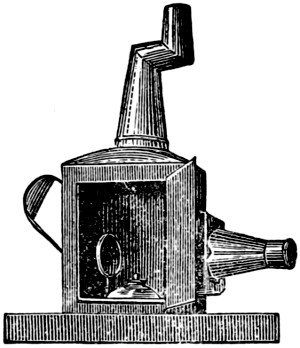
Fig. 1.
In preparing this lantern for use the lenses should be carefully cleaned with a soft cloth, and the lamp freshly trimmed. The cotton must be long enough to reach to the bottom of the lamp, and be freshly and evenly cut; the oil should be supplied to the lamp an hour before it is lighted, that the wick may become thoroughly saturated. The best oil to use is sperm oil in which camphor has been dissolved in the proportion of one ounce to one pint of oil. The object of the addition of the camphor is to increase the brilliancy of the light. If, however, sperm oil cannot be obtained, colza oil may be substituted, and this should be treated with camphor in the same way.
The room in which the exhibition is to take place should be entirely darkened, and a clean white screen or sheet hung up for the reception of the magnified pictures. The lantern is to be placed in front of the screen, upon a table or other suitable support, and at such a distance as will produce the required disc or circle of light.
The painted slide must be placed in the slide-holder upside down, and if the representation on the screen be not clear and sharp, the objective (the front lens) must be moved towards or away from the slide-holder, until the picture is well defined, or, as it is called, properly focused.
3.—THE PHANTASMAGORIA LANTERN.
We have given a description of the simpler forms of the magic-lantern burning sperm or colza oil with a solid wick, and now we will explain the construction of that known as the phantasmagoria lantern. The term ‘phantasmagoria’ was originally applied to a lantern exhibition, in which the figures on the screen varied suddenly in their dimensions, seeming at one time as though they were rushing on to the spectators, and at another vanishing away in the distance. At present this name is used as the distinctive title of a particular form of magic-lantern, otherwise known as the ‘No. 8.’
In the phantasmagoria lantern the condenser consists of two lenses (usually a meniscus convex and a double convex) fitted into a brass cell and placed in the lantern with the concave side towards the lamp. The objective is also formed of two lenses fitted into a brass tube with a diaphragm in front. This tube slides into a brass jacket fixed in front of the lantern, and the lenses are placed in the tube with their convex sides towards the condenser.
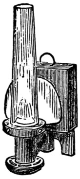
Fig. 2.
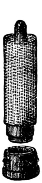
Fig. 3.
The lamp employed for illuminating the phantasmagoria lantern is the Argand fountain lamp, with hollow cylindrical wick (Fig. 2). In preparing this lamp for use, a new cotton should be fitted to it. To do this with facility the cotton should be put on to a taper-stick (Fig. 3), on to the base of which the brass wick-holder fits, the cotton can then be pushed on to the wick-holder without any difficulty. The wick-holder and wick are to be replaced in the lamp and screwed down to the bottom, and if there be any superfluous wick standing above the top of the lamp it is to be ignited and allowed to burn itself out. (This must be done before any oil is supplied to the lamp.) The wick being ready, the cistern at the back of the lamp is to be lifted out and inverted, and then filled with oil. The plug or valve which serves to close the orifice in the cistern through which the oil has been poured is to be pulled up and so held while the cistern is replaced in the lamp. The oil should be supplied to the lamp about half an hour before it is required for use, in order that the wick may be thoroughly saturated, and camphorated sperm oil is decidedly the best oil to be used in this lamp. When the lamp is first lighted the wick should be raised but a short distance above the tube that supports it, and after it is ignited all round, the lamp should be replaced in the lantern, the glass chimney (which is screwed on to a metal oxydator and gallery) placed on it, and the wick turned up as high as it will admit of without smoking. The lantern is then to be placed on the stand or table in front of the screen, at a distance of from nine to twelve feet off, a disc of six feet in diameter being obtained at the former distance, and eight feet diameter at the latter. After the lamp has been placed in the sliding tray provided for it at the bottom of the lantern, its position has to be adjusted. If the lamp be too near to the condenser, the centre of the disc will be darkened; if too far off, the margin of the disc will be obscured; the proper distance will be easily ascertained when the lamp is lighted and placed in the lantern.
4.—THE EUPHANERON LANTERN.
The phantasmagoria lantern continued for some years to maintain its character as the best lamp-lit lantern ever made. And this might have still continued, but for the discovery that the art of photography could produce transparent slides suitable for the magic-lantern.
The necessity for a superior illuminating arrangement was at once experienced, and attention was given to the lamps that were fed with the mineral oils, instead of animal or vegetable oils. Although various forms of mineral oil lamps were tried, they were not successful, until Mr. L. Marcy, of Philadelphia, conceived the idea of constructing a lantern sufficiently small to make one chamber serve as the lantern and the lamp. He used for his wick two flat cottons parallel to one another, with the tops almost in contact, and the edges of the wicks turned towards the condenser. This lamp he charged with mineral oil, and thus obtained an instrument surpassing anything of the kind previously constructed.
Since then many improvements have been made, each modification receiving a distinctive title. We have thus ‘The Silber Light,’ ‘The Triplexicon,’ ‘The Duplexicon,’ ‘The Refulgent,’ ‘The Euphaneron.’ It will not be necessary to explain each of them in detail, as they have many things in common, and it will suffice to describe ‘The Euphaneron,’ which is perhaps the best of the series.
The Euphaneron (that which shows well) differs in several important particulars from the phantasmagoria lantern. The body of the lantern (which serves to support the condenser and objective) is made of Russian plate iron, which neither rusts nor blisters. The condenser consists of two 4-in. lenses of the form we have already described, and the objective is a double achromatic combination. The outer lens of the objective, designated the ‘front lens,’ is in form a plano-convex lens. The inner lens, called the ‘back lens,’ consists of two separate lenses, one an unequi-convex lens, the other a meniscus-concave lens. This combination gives a beautifully-defined picture on the screen, with flatness of field and abundance of light.
The lamp is entirely distinct from the body, and will burn equally well either outside or inside the body of the lantern, the chimney being attached to the lamp and not to the body. The cistern of the lamp forms its base, and is filled with mineral oil. From the top of the cistern rise two rectangular tubes, sloping together as they rise; these contain the two wicks. The wicks do not stand parallel to each other, but form an acute angle with the base of the triangle towards the condenser, and this is the peculiarity that brings about the equal illumination of the disc. The wicks are raised and depressed by the action of two milled heads at the back of the lamp. Now, instead of surrounding the flames with a glass chimney, as is ordinarily the case, a metal combustion chamber is provided, and to this chamber the chimney is attached. The ends of the chamber are open, the front being closed by a glass plate, the back by a silvered reflector. Attempts have recently been made to add a third wick to this lamp, but they have not been very successful, the lantern being rendered very much hotter without affording a corresponding gain in brilliancy. The Euphaneron exhibits photographic slides in a most satisfactory manner on a disc 10 ft. in diameter. The disc is uniformly illuminated, and the picture well in focus all over the screen.
Directions for trimming the Euphaneron Lamp.—Remove the lamp from the lantern, carefully clean the front glass and the mirror. Turn back the combustion-chamber on its hinge, so as to expose the tops of the wicks. These should be cut quite smooth and straight, without any projecting filaments. The cistern should be nearly filled with the best mineral oil, and the wicks turned up a little way and lit. The combustion chamber should be now restored to its place, the lamp put into the lantern, and the chimney fixed on. The wicks should then be gradually raised as high as they will bear without smoking. In putting the oil into the lamp care should be taken not to spill any on the outside. The general directions already given for showing the pictures are then to be followed in using the Euphaneron.
5.—DISSOLVING VIEWS.
The lanterns that we have hitherto been describing have been those capable of exhibiting single pictures only; we have now to explain the production of dissolving views.
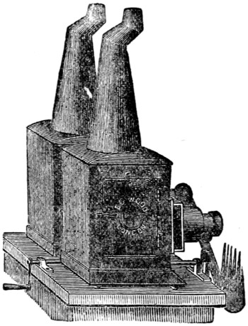
Fig. 4.
Dissolving views, as the name implies, is an exhibition of pictures in which there is a fading away of one and the appearance of another, as though the one picture grew out of the wreck of the other. To produce these results, two lanterns of similar size are required (see Fig. 4), together with some contrivance for diminishing the light forming the first picture, until that has quite faded away, simultaneously allowing that forming the second picture to fall upon the screen until this one has arrived at its complete intensity, and the first picture is no longer seen. This latter contrivance is known as the mechanical dissolver, and it consists of two serrated plates attached to a movable bar fixed to the front edge of the base upon which the lanterns are supported. These plates come immediately in front of the lanterns, and require to be so arranged that when the whole of the light from one lantern is seen on the screen, the light from the other is entirely stopped. By means of a rack and pinion motion, the plates can be moved simultaneously, and each lantern alternately closed and opened.
In order to make the discs of light produced by the two lanterns coincident, the lanterns must be slightly inclined towards each other.
There is another class of results obtained by the dissolving-views apparatus, which may be designated as the production of ‘composite’ pictures or ‘effects,’ as, for instance, a soldier is seen asleep by the watch-fire, he dreams, and the subjects of his dream appear, one after the other, on the screen, and then fade away. A ship is seen at sea; day turns into night; the moon rises; a violent storm comes on; the lightning flashes, and the ship is set on fire. A water-mill is shown with the stream running and the wheel revolving; a swan appears on the water and moves across the stream; night comes on, the wheel ceases to revolve, and the windows of the house are lit up; clouds flit across the sky; the moon rises—day returns, but the scene has changed to winter; the water is frozen, and its surface occupied by skaters, and a fall of snow takes place.
To produce such effects as these, both lanterns are required to be open at the same time, and the serrated plates forming the dissolver must be so contrived that the one which would otherwise obscure the fixed picture is turned aside, or removed altogether, and therefore only one lantern is alternately opened and closed. The foundation picture (the sleeping soldier, for example) is placed in the lantern that remains constantly open, and to this the addition (the dream) are made with the second lantern.
For dissolving views proper, only two lanterns are required, and for the simpler form of effects two lanterns suffice; but for very complex pictures, three, four, or even five lanterns are required. Any two lanterns of equal size and power may be employed to produce dissolving views; but the phantasmagoria lantern is the smallest that can be advantageously used.
6.—THE LIME-LIGHT.
We have described the typical oil-lit lanterns, and now we shall explain the production of the lime-light in its two principal modifications of the ‘oxycalcium’ and the ‘oxyhydrogen’ light. The lime-light is obtained by intensely heating a piece of lime, in which condition it emits a most brilliant light. The lime is generally used in the form of a cylinder seven-eighths of an inch diameter and one and a quarter inch long, having a hole along its centre from end to end; these cylinders are sold in tin boxes, each containing twelve.
When a box containing lime cylinders has been opened, it is best to transfer the cylinders to a wide-mouth stoppered bottle, and keep the same in a dry place, as moisture causes the lime to crumble to dust. As the lime is only required to furnish some solid material capable of being rendered incandescent, many other substances can be used for this purpose—the best substitute, if lime cannot be obtained, being chalk.
The oxycalcium light requires for its production a large loose flame, a jet of oxygen gas, and a cylinder of lime. The two instruments now to be described—one known as the oxycalcium jet and the other as the oxycalcium lamp—fully realise these conditions, and although accomplishing the purpose in somewhat different ways, each form of instrument possesses some special advantage.
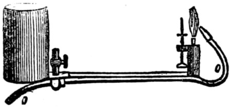
Fig. 5.
The oxycalcium lamp is represented at Fig. 5, and it consists of a vessel with an aperture in its base, is provided with a valve to close the same when needed, and is capable of holding about a half-pint of spirits of wine. This is called the cistern, and it is placed valve downwards into a second or outer cylinder rather deeper than itself. This operation opens the valve of the cistern, and allows a sufficiency of spirit to flow out so as to fill the space between the bottom of the cistern and the bottom of the outer cylinder. From this outer cylinder proceeds a long horizontal tube, terminating in a small chamber that holds the wick, and it is here that the lamp is lighted.
Behind the wick is a steel pin for holding the cylinder of lime, and in front of the wick is the small end of a bent tube (marked o o), carrying the oxygen gas. This oxygen gas tube passes along the under side of the tube connecting the outer cylinder with the wick chamber, and extending some little distance behind the outer cylinder, there terminates in a tap. This tap is to be connected with the bag containing the oxygen gas by means of a flexible pipe.
In arranging the oxycalcium lamp for use the cistern should be filled with spirits of wine, and the wick cut off smooth. The lime cylinder is to be placed on the support, and the tap o connected with the bag containing the oxygen gas.
A weight equal to about 40 lb. or 50 lb. is to be placed on the bag, and the apparatus is ready for use. The lamp is to be lighted at the wick and the gas admitted by gradually turning the tap at the end of the tube o; the tap attached to the bag having been previously turned fully on. The oxygen gas now issues from the point of the tube in front of the flame and forces the flame against the lime, producing thus the oxycalcium light.
The quantity of gas admitted requires to be regulated to the size of the lamp flame, for if the gas be in excess, the lime will be cooled down and the light diminished. A similar loss of light will result from having too little gas; so that some attention will be required to enable the operator to adjust the apparatus satisfactorily.
The wick should be carefully put into the wick-holder in straight lengths, not twisted together, and not too tightly packed. A slight separation should be made in the top of the wick to allow the stream of gas to pass freely. The point of the jet should be about one-tenth of an inch below the top of the wick, and should not project into the wick. The wick should be kept up close to the point of the jet, and not be allowed to bend towards the lime cylinder.
The spirit to be used with the oxycalcium lamp is to be alcohol or the best methylated spirit; paraffin spirit will not do. It is best to renew the wick each time the lamp is used.
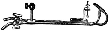
Fig. 6.
It is now necessary to describe the other form of oxycalcium light—the oxycalcium jet.
The oxycalcium jet is shown at Fig. 6, and it will be seen that the cistern and wick-holder required by the oxycalcium lamp are both dispensed with. There are, instead, two horizontal tubes lying side by side, each having a stopcock at one end, the other end of each tube being turned up, one—the hydrogen tube—at right angles and inserted into the stem of a sort of oblique T-shaped tube. The end of the other horizontal tube—the oxygen tube—is bent into a bow form, so that it may pass through the crosspiece of the oblique T-shaped tube before mentioned. The stopcock of the oxygen tube is to be connected with the bag containing the oxygen gas, and the stopcock of the hydrogen tube is to be attached by a flexible tube to any of the gas-fittings in the room where the apparatus is to be used. By this arrangement a stream of ordinary hydrogen or street gas will pass through the hydrogen tube into the oblique T-shaped tube, and will issue out at its open end, where it is to be lighted. This flame, by the action of the stream of oxygen issuing from the end of the oxygen tube, will be forced against the lime cylinder, and produce, as in the former case, the oxycalcium light. The same attention to the adjustment of the quantity of oxygen gas to the size of the hydrogen flame that was necessary for the oxycalcium lamp is equally needed with the oxycalcium jet, and by means of the two taps this can be managed with the greatest facility. It is usual to drill a hole through the flat part of the key of the oxygen stopcock, so that it may be readily distinguished. It sometimes occurs that the gas-fittings from whence the supply of hydrogen is to be obtained have immovable nipples. In this case it will be found advantageous to connect, by means of a T-piece, two or even more of the nipples with the tube that is to convey the hydrogen to the jet; closing, of course, those that are not thus used.
It is obvious that in using the oxycalcium jet the operator is dependent for his flame upon a supply of the ordinary hydrogen or street gas, and therefore this modification of the oxycalcium apparatus cannot be employed in any place unprovided with the means of obtaining the same. The oxycalcium lamp, on the other hand, as it carries with it the means of producing the required flame, can be used anywhere. The light obtained by the oxycalcium arrangement, although not equal to the oxyhydrogen light, is admirably adapted for exhibitions on a moderate scale, and it requires only one gas-bag.
In both of the oxycalcium arrangements the lime cylinder does not need any alteration of position while in use. The proper distance between the oxygen jet and the surface of the lime varies from one-eighth of an inch to one-quarter of an inch.
7.—OXYHYDROGEN JET.
Having explained the oxycalcium lamp and jet, we have now to describe the oxyhydrogen jet, by which the brightest form of lime-light is produced. The oxyhydrogen jet differs from those previously described in one important particular, viz. that the two gases are mingled together as gases before being ignited. Like the oxycalcium jet, it consists of two tubes lying side by side (see Fig. 7), having a tap at one end of each. The ends of these tubes are inserted into the base of a small chamber, from which proceeds a single curved tube, which rises up in front of the holder upon which the lime cylinder is placed. The end of this tube is contracted by a platinum point screwed into it, and this forms the jet. Two bags are required for this light, one containing hydrogen gas (common house gas will do), and the other bag filled with oxygen gas, and these bags are to be connected with the taps at the end of the jet by means of flexible tubes in the usual manner. The two gases are thus kept separate until they enter the chamber at the base of the curved pipe. This chamber is provided with layers of wire gauze, so as to facilitate the admixture of the gases, which eventually issue thoroughly mingled from the point of the jet. In this condition they are capable of being ignited, and as soon as the flame impinges on the lime cylinder a most intense light results.
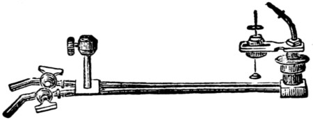
Fig. 7.
The lime-holder of the oxyhydrogen jet is made to slide, so as to be capable of being moved towards or away from the point of the jet. This adjustment is necessary to rectify any slight difference in the diameter of the lime cylinders, for, in order to obtain the full amount of light, the face of the lime cylinder requires to be brought as close to the point of the jet as it can be without being in contact with it. In addition to this movement, the stem on which the lime cylinder is supported is also made to revolve, in order to provide a fresh surface of lime to be presented to the action of the flame. The heating power of the flame of the oxyhydrogen gases is so intense that a cavity is soon burnt in the face of the lime cylinder, and if this part of the cylinder were to be allowed to continue opposite to the jet, the light would be greatly diminished and the general effect marred. To provide against this, the stem of the lime-holder is made with a screw at its lower end, this screw working in a corresponding socket, so that by turning the stem of the lime-holder round on its axis a second motion in a perpendicular direction is also given to it. By this means the face of the lime passes before the point of the jet in a spiral direction, and consequently the same part of the lime cylinder is not brought a second time under the action of the flame. In order to facilitate the rotation of the lime cylinder, the screw is sometimes set in motion by clockwork; but the better plan is to turn the lime by means of a horizontal rod with bevel wheels.
Having described the various forms of apparatus constructed for producing the lime-light by means of oxygen and hydrogen gases, a few general observations will not be out of place. It should be borne in mind that oxygen gas is a supporter of combustion, and is neither explosive nor inflammable. The hydrogen gas will ignite, but will only do so in the presence of oxygen. With the oxycalcium lamp and oxycalcium jet, there is complete safety from explosion. In the oxyhydrogen jet there is also complete safety if care is taken not to fill up the hydrogen-bag with oxygen, and vice versâ. Such an admixture is explosive, and nothing can prevent an explosion when a light is applied. The contents of one bag will not pass into the other during an exhibition, and even if the weights were to fall off the bags, the only effect would be to put the light out.
8.—THE GAS AND GAS-BAGS.
Several times in describing the production of the lime-light reference has been made to gas-bags; and now we will explain more fully what they are. Gas-bags are usually made of stout india-rubber cloth, wedge-shaped, their length being half as much again as their width, and the base usually equal to their width. A tap is provided and attached to the apex of the bag, so as to allow of the admission and expulsion of the gas. In order to press out the gas from a filled bag, two boards are used. These boards are of similar dimensions to the bag, and being hinged together along one edge, can be separated to allow of the introduction of the inflated gas-bag. A projecting ledge is fixed on the outside of the upper board, about eight inches from its end, against which the weight required to press out the gas can rest. The weights should be square-shaped, and the most convenient size is a half-hundredweight. When two bags are required (as in the case of the oxyhydrogen light), the double pressure-board (Fig. 8) should be employed; the two bags are then placed one above the other, and one set of weights only is required instead of two sets. The weight required to be used with a bag of eight feet capacity when employed for the oxycalcium lamp or jet should be about 56 lbs., but at least three times that amount should be placed on the bags for the production of the oxyhydrogen light.
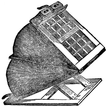
Fig. 8.
It is not desirable to keep either oxygen or hydrogen gas in india-rubber bags for any length of time. Oxygen can be kept for a few days or a week, but any hydrogen gas that may remain in the bag after an exhibition should be expelled before the bag is refilled. When two bags are in use, each should be marked; O on the oxygen bag, and H on the hydrogen bag; and the bags should not be used interchangeably; i.e., hydrogen gas should not be put into an oxygen bag, nor oxygen into the hydrogen bag. In arranging the apparatus, place the pressure boards and bags where they will not be meddled with. Let the weights be securely placed on the pressure boards, so that they may not slide or roll off during the exhibition. Do not on any account allow any one to stand upon or press the boards with his foot as a substitute for, or in addition to, the weights. The lime cylinder should be wiped clean from dust before it is put upon the holder, and it should be exposed to the flame of the lamp or simple hydrogen flame some minutes before the oxygen is turned on, so that it may not fracture when the light is being produced. When all arrangements are complete, the hydrogen should be turned on and lighted, and oxygen should be gradually turned on until the requisite degree of light is obtained. With the oxycalcium light some exhibitors use the compressed oxygen, the gas being compressed into an iron cylinder, and thus bags, boards, and weights are not needed. This arrangement has the advantage of portability, but the cylinders have to be filled by means of a steam pump—a thing not always to be obtained. When a cylinder is used it should be placed as close to the jet as possible, and the flow of gas must be regulated by the valve of the cylinder, and not by the tap of the jet.
9.—OXYGEN AND HYDROGEN.
The two gases, oxygen and hydrogen, required for the production of the lime-light need now some separate notice, as it often occurs that those who use these gases for dissolving-view exhibitions have to prepare the one—sometimes both—for themselves.
Oxygen gas is a simple elementary body, and is most extensively diffused throughout our earth. It is one of the constituents of the atmosphere surrounding our globe, and also of water, as well as of nearly all the substances known as acids. It has never yet been met in its separate or uncombined state, and therefore it can only be obtained by decomposing some substance of which it is a constituent.
The material most convenient for obtaining oxygen gas for lime-light purposes is chlorate of potassa. Two parts of this material (by weight) is mixed with one part of powered black oxide of manganese (this is known as ‘oxygen mixture’). The oxide of manganese does not supply any of the oxygen, but its presence facilitates the decomposition of the chlorate of potassa. The apparatus used for generating the gas is shown at Fig. 9. It consists of a copper or iron vessel (A), forming the retort or generator, a glass bottle-shaped vessel (B), which is the purifier, the two being connected together by a flexible tube. It will be seen that there are two tubes proceeding from the top of the purifier, one of which reaches nearly to the bottom of the vessel, and the other only just enters into the top. The former, or long tube, is the tube by which the purifier is attached to the retort; the latter, or short tube, is that which connects the purifier with the bag.
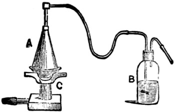
Fig. 9.
The method of charging the apparatus is as follows. Put into the retort about a pound and a half of oxygen mixture; pour into the purifier a sufficient quantity of water to about two-thirds fill it. Place the retort on a clear but not fierce fire, or over a gas furnace, and unite it to the long tube of the purifier (B). Attach the short pipe from the purifier to the gas-bag, and open all the taps, so that there may be a free passage-way from the retort to the bag. In a few minutes the gas will be given off, and will manifest itself by rising in bubbles through the water in the purifier. If a fierce fire be employed, the gas will be given off with undue rapidity and will pass through the purifier in volumes, so that it only becomes partially washed. A rapid but regular succession of gas is most to be desired. Should the gas come off with great violence, the retort should be lifted from the fire without disarranging the apparatus, and when the excessive rapidity is moderated it can be replaced. It is not, however, desirable to remove the retort from the fire if it can be avoided, for it not unfrequently happens that when the retort cools down, with only partially decomposed material in it, waste is the consequence, as it is not quite easy to re-establish the decomposing process. When the gas has entirely come off—which may be known by the cessation of the bubbles in the purifier—the top of the bag should be closed, the retort taken from the fire, detached from the purifier, and stood aside to cool. When cold, the residuum may be readily washed out with water, and when dry, the retort is ready for use again. The purifier should be emptied and washed out also. Always blow through the flexible tubes leading from the retort to the purifier, and wash out the metal tube of the retort in order to remove any solid material that may have been deposited there from the gas.
There has recently been manufactured a very neat oxygen gas-generator and gas-burner combined. The inventor proposes to prepare the oxygen in the room where the exhibition is taking place, and while using the lanterns. But as this apparatus would be very difficult to manipulate with, even by an experienced operator, it cannot be recommended for general use.
With regard to the hydrogen gas, it is always best to use the ordinary house gas, or if that cannot be obtained, to use the oxycalcium lamp, as the preparation of the pure hydrogen gas is troublesome, and not quite free from danger.
10.—SLIDE PAINTING, ETC.
The preparation of magic-lantern slides for home use (although, perhaps, not equalling the bought ones in quality) is a great source of pleasure, and a few hints on this part of our subject will probably be acceptable. A number of very amusing slides may be made by cutting grotesque or other figures out of black paper, and pasting them on glass slips, and after the pictures are dry, giving a little detail by slashing the picture with a sharp penknife in places where needed. If these figures be first drawn on tissue paper, coloured, and then cut out, the effect is still more pleasing. Or, if preferred, sheets of these figures in black can be bought, and thus the trouble of drawing them will be saved.
A very efficient set of astronomical slides may be constructed out of blackened cardboard with the aid of a few punches, some different-sized needles, and some of the coloured gelatine bon-bons. Having cut the card of a size suitable for the lantern, and marked on it a circle of the same diameter as the lantern condenser, prick holes in the card by aid of the needles, so as to represent the principal constellations and nebulæ, illustrations of which will be found in most works on astronomy. The relative positions of the planets may be shown by punching holes in the cardboard and covering them over with gelatine. When the holes are punched, the orbits may be traced by a very minute row of holes, pricked with a fine needle, the circles having first been marked with a pair of compasses.
For larger diagrams representing the planets singly, a sharp penknife and a pair of compasses would, combined with a steady hand, produce wonders.
The painting of magic-lantern slides on glass is a rather more difficult task, and some knowledge of the rules of the art of painting in general will be found most useful. The colours and brushes to be used are sold in boxes, and the number of colours can be readily increased by mixing. The following articles may be considered necessaries. Easel, glass to paint on, pencils, dabbers, etching-needles, fixing varnish, and the following colours: Blue, Nos. 1 and 2, crimson, amber, brown, mauve, black, light green, dark green, orange, purple, and scarlet. Having obtained these articles, proceed as follows. Make a drawing of the picture required, of the right size, on white paper, and place this under the glass upon which the picture is to be painted. The outline is then to be traced on the glass in Indian ink with a fine pen. This part of the work, however, can be dispensed with if the glasses be bought having pictures already outlined on them. If the subject of the picture be a landscape, the outlined glass is to be turned upside down, and the sky filled in first, commencing at the horizon with a pale tint, which is to be increased in density as the edge of the picture is approached. To remove any superfluous colour, a dabber is used.
When this colour has dried, the other parts of the picture are painted in succession with appropriate tints, warm tints being employed for the objects in the foreground, neutral or cool tints for the background.
This having been done, the picture has then to be coated with the fixing varnish, either using a brush or pouring it on as a photographer would do; or, when it has covered the surface, allowing it to run back into the bottle from one of the corners. The varnish is then allowed to dry, after which the picture is again to be examined, the shadows of the buildings and the trees are to be filled in, and the colour strengthened where the picture seems to need it. Snow and moonlight effects are produced chiefly by removing the colour in places by means of a knife and needle-point.
The rules given above apply also to the colouring of photographs for the magic lantern.
II. How to Make a Cheap Magic-Lantern. By Frank Chasemore.
If you were to go to a shop to buy a lantern like the one I am going to describe, it would cost thirty-five shillings, but you will be able to make it for fourteen or fifteen. I will tell you what mine cost me, including the slides. The lantern cost me fifteen shillings.
£ s. d.
Lantern 0 15 0
Colours 0 10 6
Glass 0 5 0
Paper 0 1 0
Varnish 0 1 0
£1 12 6
With these colours and glass I have painted 250 slides, which to buy would cost two shillings each, and the cost of lantern and 250 slides would thus be:—
£ s. d.
Lantern 1 16 0
250 slides at 2s. 25 0 0
26 15 0
1 12 6
£25 2 6
making a clear saving of £25.
Besides this, you have the double pleasure of making the lantern and painting the slides, and showing it as your own work. The picture shown by this lantern will be nine or ten feet in diameter, and will be large enough to show full-sized slides if you should at any time buy any. If you do buy, I should recommend the uncoloured photographs (1s. 6d. each), to be got at all shops where they sell lanterns. By making two of these lanterns you can use them for dissolving views, which is by far the best way to exhibit the slides. Many brilliant effects can be obtained with two lanterns that it would be impossible to do with a single lantern. I should certainly advise you to try this. Both lanterns can be made at the same time; the directions for one will do for both. But we must get on with our description.
First of all get a carpenter to cut you a deal board, free of knots, six feet six inches long, nine inches wide, and half an inch thick. This must be planed smooth on both sides. If you have a plane, do this yourself. Now with a fine saw cut four pieces off the board, each twelve inches long, and two pieces nine inches long. These are to make the body of the lantern with. Take two of the long pieces and the two short pieces, and reduce the width to six inches. These will be the top, bottom, back, and front of the lantern. Now you must put the pieces together by dovetailing; or you had better get the carpenter to do this for you, as unless you are used to this work you would be sure to make a mess of it. Do not glue the pieces together yet. Take the piece of wood that is to serve for the top, and draw lines with a pencil from opposite corners, like Fig. 1. Now with a pair of compasses, open one inch and a half apart, put one point at the point where the two lines cross each other, and mark a circle with the other point. This circle must be cut out either with a keyhole saw or with a gouge, smoothing off with a rough file.
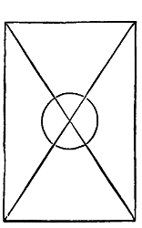
Fig. 1.
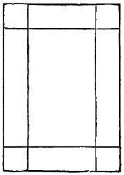
Fig. 3.
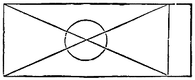
Fig. 2.
Now take the piece of wood that is to be used for the front of the lantern and draw a pencil line across it, two inches from the top end, and then cross the other part with pencil lines (Fig. 2), as you did the top, and with the compasses open an inch and three-quarters make a circle as before and cut it out. Now take the piece of wood to be used for the right side of the lantern and mark it thus (Fig. 3). Draw lines across each end two inches from the edges, and along the side one inch and a half from the edges. Cut out the middle portion evenly up to the lines. This will form the door, and if you have cut the piece out with a keyhole saw it will do to be fastened on with hinges. If not, you must make another piece for the door. Now, round the bottom of the two sides and back bore holes with a half-inch centrebit. These holes must be one inch and a half from the centre of the hole to the edge of the wood. Three in the back piece and four in each side will be enough. These holes are to supply air for the lamp. Now you will want some sheet tin to line the lantern with. This you must buy. Get two and a half sheets of thin, and two and a half of very stout. The thin will be threepence each, the stout sixpence each. Cut pieces from the thin tin to line the lantern with—two pieces eight inches by ten inches, two pieces five by eight, one piece five by ten, and one piece five by eleven. Punch holes all round each of these pieces. This can be done with the sharp end of a file. Put the tin in its place on the top, front, and right side, and mark on it, through the holes, their exact size, and cut the tin away a little larger than the holes. Now you can put the linings in their places and fasten on with small tacks. Those used by upholsterers are the best. The tin at sides, back, and front, is cut short, so as not to cover the holes at the bottom. The tin can be easily cut with a large pair of scissors. The door must be lined with tin. When all the parts are lined you can glue the joints and put the body together, fastening with small brads. This can now be put on one side to dry and set firm, as we shall next set to work to make the stage and nozzle.
Before you can do so you must get your lenses and reflector. These will cost you more than any other part of the lantern twice over. The lenses will be 10s. 6d., and the reflector 2s. Ask for, or write for, a pair of lenses for No. 6A lantern, three and a half inches, and a four-inch reflector. First of all we must set the lenses. Take the largest, and cut a strip of thin tin half an inch wide, and long enough to go right round the lens and lap an eighth of an inch. The best way to measure this is with a piece of paper, cut into a strip and passed round the lens, and cut to the exact length of the circumference of it. Place this paper on your tin and cut the latter an eighth of an inch longer than the paper. You must now solder the ends of this strip of tin together to make a ring. To do this you must have a soldering bit, and as this is always useful you had better buy one.
Take a small piece of clean tin, put on it two or three drops of chloride of zinc, and in this put a small piece of solder. Put the bit in the fire to get hot—but not red-hot. When hot, rub the point with a file till it is bright, and put it on the solder, which will immediately flow and cover the point of the bit. This is called tinning the bit, and must always be done when the bit gets red-hot, as that burns off the tinning.
Put your bit in the fire to get hot, and while it is there bring the ends of the tin strip together so that they lap an eighth of an inch. Dip a camel-hair brush in the liquid and rub the joint between the lapping and an eighth of an inch outside. Put a small piece of solder at the top of the joint. Now if the bit be hot enough put it on the solder, and, as soon as it has melted it, draw it slowly along the joint, and the solder will flow after it and make a firm joint. In making joints like this, the parts of the tin lapping must touch each other closely. When the joint is cold, take a small hammer and turn in one edge all round a sixteenth of an inch. This will be easily done by gently tapping the edge with the hammer over a piece of wood, such as a toothpowder-box or ribbon-roller. In doing this you must be careful not to put the band out of the round. When this is done, put the lens inside, resting on the turned-in part. Now get a piece of brass wire a sixteenth of an inch thick, and about a quarter of an inch less in length than the tin strip was, and bend it into a ring, but do not fasten the ends together. Put the ring inside the band against the lens, and it will spring against the sides and hold the lens firmly in its place. This lens, with its setting, is to be placed inside the lantern in the large hole in the front of it, with the lens towards the back of the lantern.
Now we must set the other lens. Take a piece of the thin tin two and a half inches wide, and long enough to go round the lens and lap an eighth of an inch. In cutting this you must be careful to keep the sides and angles square, or it will not be true when made into a tube. Now get a roller for silks about an inch and a half thick and roll the tin round it to make a tube by bringing the shortest edges together. Be careful to make the tube nice and round and smooth; lap the edges an eighth of an inch, and solder them together as you did the other tube. Turn in one edge all round a sixteenth of an inch, put the lens inside, resting on the turned-in part, and fix it with a wire ring. Now take a strip of tin an inch wide and long enough to go round this last tube and lap an eighth of an inch. Bring the edges together, lapping an eighth of an inch, and solder.
This is the tube to be fixed in the nozzle, for the front lens tube to slide in, to regulate the focus. Round this little tube, half an inch from the edge, mark a line.
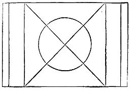
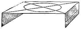
Fig. 5.
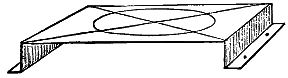
Fig. 4. Fig. 6.

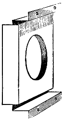
Fig. 7.
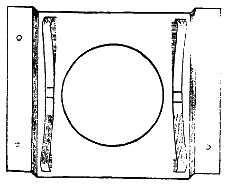
Fig. 8. Fig. 9.
Now we will get on with the stage. For this you will use your stout tin. Take one of the plates and mark on it a piece five inches by eight, being very careful to make it quite square at the corners. Cut this piece of tin out. Now draw a line across each end at half an inch from the edge, and another line an inch and a half from the edge (Fig. 4). Cross the middle portion by lines drawn from opposite corners, and with your compasses mark a circle three inches and a half in diameter. Cut out this circular portion, being careful not to bend the plate; but if you do you must straighten it again with a piece of wood, bend the ends down along the inner line till they are at right angles with the other part of the plate (Fig. 5). Now bend the tin outwards along the other lines till it is at right angles to the other part (Fig. 6). Punch two holes about an eighth of an inch wide in each of the turned-out parts. These holes are to screw the stage to the lantern by. Next you must get two pieces of clock-spring about a quarter of an inch wide and four inches and seven-eighths long. Bend them into bows about an inch high, and turn the ends outwards a little (Fig. 7). Solder these into the inside of the stage by the middle at the top and bottom of the hole (Fig. 8). Cut another piece of tin seven inches and seven-eighths by seven inches and a quarter, and cut a circular hole in the middle four inches in diameter. Mark a line across each end an inch and an eighth from the edge, and bend the plate at right angles at each end. This is to make the spring clip to hold the slides; it is put inside the stage, resting on the springs, and with the turned-out parts outside (Fig. 9).
In cutting the tin for the next part, you must be careful to keep the sides and angles square; also in bending it into a tube and soldering it. Mark out on your tin plate (stout tin) a piece eleven and a quarter inches long and four and one-eighth inches wide, turn this into a tube by bringing the shortest edges together round a bottle, lap them a quarter of an inch, and solder the joint; now very carefully turn out one edge all round, one-eighth of an inch, being careful not to disturb the round. This can be done against the edge of a flat-iron by gently tapping with your small hammer. Cut out a circular piece of tin three inches and a half in diameter, and in the centre cut out a circular hole exactly the size of the small tube the lens-tube slides in; pass this tube half way through this hole, and solder it in, being careful that it is squarely in; now put this piece into the end of the large tube, not the turned-out end, so that the side that is soldered is inwards, and solder this on the inside of the tube. Next solder this tube, which is the nozzle of the lantern, on to the outside of the stage, being careful that the holes in the stage and tube correspond. You had better strengthen the stage by soldering corner pieces in where the turn-out parts are (Fig. 10). Now the stage and nozzle is ready to be screwed into its place on the front of the lantern, being careful that the centre of the holes are all in the same straight line; but before screwing it on, all the tin visible must be blackened with dull black paint, which I will tell you how to make at the end of this section. The inside of the lantern must also be painted with this black paint, as well as the inside of the front lens-tube. In this tube there must be what is called a diaphragm. To make this, take a piece of thin tin an inch and a quarter wide, and long enough to go round the inside of the lens-tube; solder the edges together, and close the end with a circular piece of tin with a circular hole in the middle of it a little less than half an inch in diameter. Blacken this and push it into the tube, so that the little hole is about half-way in. The lens-tube is to be pushed into the nozzle with the lens inside. To make the chimney, take a piece of tin six inches wide and nine inches and three-quarters long, bend it into a tube, and lap a full eighth of an inch; solder up the joint; then cut four notches in the top about three-quarters of an inch deep (Fig. 11).
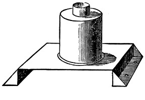
Fig. 10.
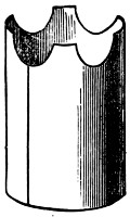
Fig. 11.
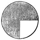
Fig. 12.
Now mark on a piece of tin a circle four inches and a quarter radius, or eight and a half inches wide; cut this circle out. Now cut out a quarter of the circle (Fig. 12), bring the cut edges together, lap them a little, and solder the joint, so that it makes a small tin cone (Fig. 13). Put this on to the four points on the top of the chimney-tube, and solder those points into it securely, and your chimney will be finished and look like Fig. 14. This must be pushed into the hole at the top of the lantern.
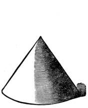
Fig. 13.
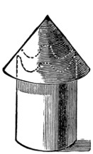
Fig. 14.
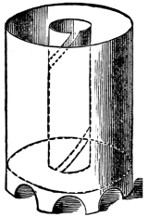
Fig. 15.
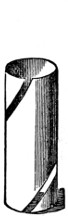
Fig. 16.
Now for the lamp, and your lantern will be finished. You had better make this, as it would cost you 10s. 6d. to buy, and you have nearly all the materials required. Cut a piece of stout tin nine inches and three quarters long and three inches and three quarters broad; make it into a tube by joining the short edges together, lapping them a little, about an eighth of an inch, and soldering the joint. For the bottom cut a piece of tin round, the exact size to fit tightly into the tube; in the middle of this cut a circular hole three-quarters of an inch in diameter, solder this in the lamp so that it is half an inch from the bottom end, and then cut the half-inch that projects like you did the top of the chimney. Now make a tube of tin to fit the hole in the bottom, and long enough to come level with the top of the lamp; solder this up, and into its place in the lamp (Fig. 15). Next you must get a short piece of brass curtain-rod that will just fit tightly over this last tube and be the same length. In this brass tube you must cut a spiral slot, running from top to bottom, and going once round. The slot is to be cut quite through the brass (Fig. 16). The best way to do this is to cut a piece of wood, about eight inches long, and thick enough to fit very tightly in the brass tube; then with a sharp file make your cut. The cut is to be about one-sixteenth of an inch wide. Now push this brass tube on to the tube in the lamp, and fix it by pressing the brass in a little.
The next thing to make is the wick-carrier. Make a short tube of tin three-fourteenths of an inch long, and to fit easily over the brass tube; round the bottom of this short tube put a band of stout tin one-fourth of an inch wide; through this band drill a hole one-sixteenth of an inch, and solder a sixteenth-of-an-inch wire through it, so that it projects one-eighth of an inch inwards, and one-eighth of an inch outwards. This little wick-carrier must be notched with a penknife (Fig. 17), so that it is covered with little points directed downwards; these points are to catch in the wick and hold it firmly.
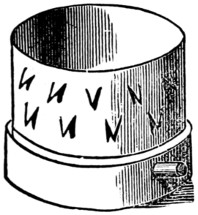
Fig. 17.
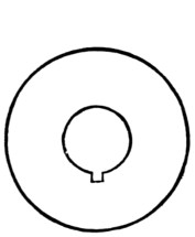
Fig. 18.
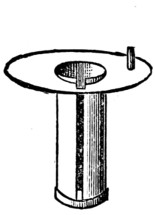
Fig. 19.
If this wick-carrier is put on the brass tube in the lamp, with the inside point in the spiral slot, as it descends it will turn to the left, and as it is lifted up it will turn to the right; consequently if it is turned to the right or left, it will ascend or descend, according to the way it is turned. To turn this wick-carrier we must have the following contrivance: Cut out a circular piece of stout tin that will fit easily into the lamp, and in the centre cut out a circular hole that will allow the wick-carrier to pass easily through it. At one side of this circular hole cut a little slot one-eighth of an inch each way (Fig. 18). Next make a tube of tin that will fit inside this hole, and will let the carrier pass freely up and down inside, but the edges of the tin must not be joined, but be an eighth of an inch apart. Solder this tube in its place in the circular tin, projecting through about a quarter of an inch, and so that the opening down the side of the tube corresponds with the square slot in the top. Solder a band of tin one-eighth of an inch wide all round the bottom of this tube to keep it firm (Fig. 19). Punch a hole in the top about a quarter of an inch from the edge, and fix a one-sixteenth wire in it about half an inch long.

Fig. 20.
Put this tube over the brass tube, so that the slot at top corresponds with the top of the spiral slot. Put the wick-carrier in its place, with the inner point in the spiral, and the outer point in the slot in the tube; and by turning the top to right or left the wick-carrier will ascend or descend, and, when the wick is fixed to it, will raise or lower the wick. To turn this top something more is wanted—that is, a movable top to carry the lamp-glass; this can be made to turn the movable top to raise the wick-carrier. For this you must get a piece of sheet-brass or copper—brass will look best, but copper is easiest worked. Whichever you decide upon, it must be a circular piece three and a half inches in diameter, and less than one-sixteenth of an inch thick. This copper is to be worked into the shape of a felt hat, with a crown three-quarters of an inch high, and one and a half wide. To do this you must make a block of hard oak wood six inches square and three inches thick; cut a hole in the middle the shape and size of the crown of the hat; this is to be like half a ball (Fig. 20).
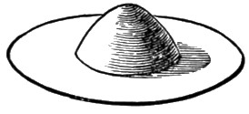
Fig. 21.
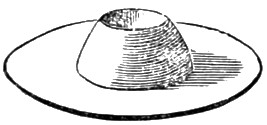
Fig. 22.
Now make another block two inches thick and six inches square, and bore a hole in each corner to screw the two blocks together by with four-inch screws. Make a hole right through the top block one inch and a half wide. Now make your copper red-hot and chill it in cold water—this will soften it; put it on the lower block with the centre of the copper exactly over the centre of the hole in the block, place the top block on the copper, and screw the two blocks together as tightly as you can. Now make a piece of oak three and a half inches long, and one inch and three-eighths thick, into a roller, and round one end. Put the rounded end in the hole, resting on the copper, and strike it repeatedly with a heavy hammer or mallet. This will drive the copper into the hollow in the bottom block. You must make the copper soft by making it red-hot repeatedly, and you will find that it will be easily worked into the hollow. As soon as it is forced quite into the hollow in the lower block you must unscrew the two blocks and finish the fitting by hammering with a round-faced hammer. Your copper will now be like Fig. 21. Now you must file off the top of the crown, so as to make a hole at the top three-quarters of an inch in diameter, like Fig. 22.
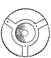
Fig. 23.
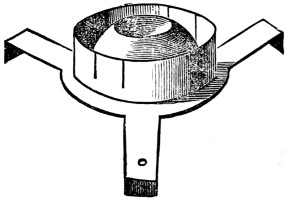
Fig. 24.
Next you must cut the brim like Fig. 23, making three projections three-eighths of an inch wide, and three-quarters of an inch long. Now one-sixteenth of an inch from the crown of the hat bore a hole one-sixteenth of an inch at the end of each projection. Bend the outer end of each projecting arm a little less than a quarter of an inch downwards, till it is at right angles to the other part. Make a ring of thin tin three-eighths of inch wide, and one inch and five-eighths in diameter; cut the bottom edge away, leaving three projecting points one-sixteenth of an inch wide and a quarter of an inch long, equidistant from each other, put these projections through the little holes round the crown of the hat, and bend them inwards underneath. This will hold the ring tightly in its place. Now put this hat on the top of the lamp, and mark on one of the arms the place where the iron wire in the movable lower top comes, and then bore in that arm a hole one-eighth of an inch in diameter, and put the top on, passing the upright wire through this hole. Your top will now be like Fig. 24. The ring is to hold the chimney, and should have four or five slits in it a quarter of an inch deep, to clip the glass.
Now solder a handle to your lamp. Make a ring of tin a quarter of an inch wide, and one inch and a quarter in diameter, and solder the two ends to the lamp.
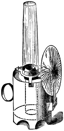
Fig. 25.
On the other side you must make the loop to hold the reflector. Take a piece of tin one inch wide and three inches long, and bend the ends at right angles to the middle, each end to be three-quarters of an inch long. Solder these ends to the front of the lamp. On the front of this piece of tin solder another an inch and a quarter long and three-quarters of an inch wide, soldering only the ends. This will be the loop to slip the hook on the back of the reflector in, and will keep it in its place. Your lamp is now quite finished, and will be as represented in Fig. 25. In fastening on this slip care must be taken to put it in such a position that when the reflector is in its place the centre of the reflector will be one inch higher than the top of the lamp, that is, the cut crown of the hat.
When using the lantern the lamp must be placed under the chimney, and pieces of board put under it to bring the centre of the reflector opposite the centre of the lens.
Now put a wick in. These wicks are circular, and about three inches and a half long. When buying them, take your wick-carrier with you to get the right size. They should fit tightly over this. These wicks can be bought at the lantern-shops, and are one shilling or one-and-sixpence a dozen. Put oil in your lamp, about two-thirds full. Light your lamp and put it in the lantern. Put the chimney on, put the lenses in their proper places, and try the lantern. If it gives a clear, sharp disc on the wall your lantern is all right, and ready to show the slides. If the disc is cloudy or has dark patches, move the lamp about till you get it clear. Move the front lens till the end of the disc is sharp.
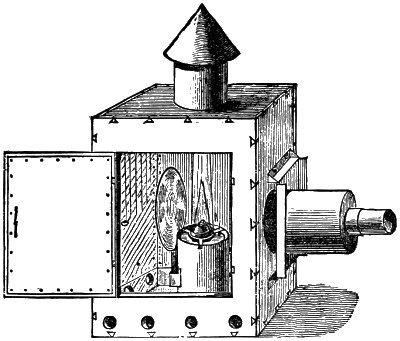
Fig. 26.
You can paint your lantern all over with black paint. Brunswick black is the best to do this with. It makes the tin parts look nice. If you prefer it, and I think it is far the best, you can make your lantern of mahogany instead of deal, and polish it, and blacken the tin parts only. Mahogany board can be got for this very little dearer than deal. If you were to solder a brass-wire ring round the outside of the edge of the tube that carries the front lens, it would make it stronger and easier to regulate the focus, besides giving it a more finished look. If the nozzle and focusing-tube were made altogether of this brass plate it would add to the finish.
III. How to Make the Slides for a Magic Lantern.
A magic lantern without slides is not of much use. These slides cost a good deal to buy, the price, ranging from two shillings to a guinea, being regulated by the time and skill expended in their production. In this section I will tell you how to make your own slides at a small outlay for materials. The time and skill you must supply yourselves.
The materials required are—a glass-cutter; some strips of patent plate-glass four inches wide—the glass of the thickness called eleven-ounce glass; thin black paper, crystal varnish, turpentine, tubes of water-colours, three or four sizes of sable-hair pencils; a good-sized camel-hair brush, with the hair cut straight off half-way down, for varnishing; some glue, two or three small dabbers made of fine linen or kid stuffed with wool, a palette, an easel, and a penknife.
The colours required are opaque black, warm brown, blue, dark green, yellow, and crimson. The palette can be made of a piece of glass six inches square, with a piece of white paper pasted on the back.
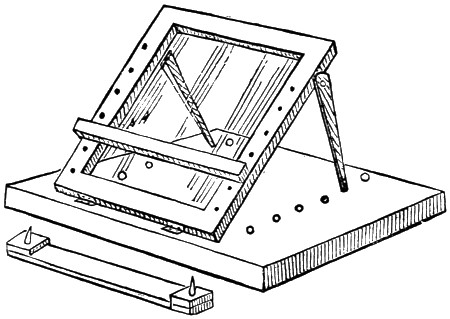
Fig. 1
The easel you can make for yourselves. Fig. 1 will show how mine is made. A board twelve inches square and one inch thick forms the stand. To this, at about one inch from the front edge, is fastened by two hinges another smaller board, eight inches wide and eleven inches long from top to bottom, having a square hole six inches wide and nine inches long cut out of it, making it into a frame. This hole is filled with a plate of glass by glueing strips of wood all round inside the frame at the back for the glass to rest upon. The front surface of the glass must be flush with the front surface of the frame.
Up the front of both sides of the frame holes are bored about half an inch apart for the pegs in the shelf to fit into. This shelf is a piece of wood eight inches long and half an inch square. In the back of the shelf are fixed two iron pegs, which fit into the holes in the frame to keep the shelf in position. At each side of the frame is a wooden support screwed on to the outside by one end, so that it can be moved freely backwards or forwards, hinge fashion: the free end of each support fits into holes bored in the stand. By moving the supports backwards or forwards, and putting them in the holes in the stand, the easel can be lowered or raised at pleasure.
The upper surface of the stand is covered with white paper. You will require a hand-rest to keep the hand from touching the painting. This is made out of a piece of thin wood (cigar-box wood does nicely) eight inches long and one inch wide. To one side of this, at each end, glue a piece of the same wood one inch square, and in these pieces fix the iron pegs to fit into the holes in the frame of the easel.
When using the easel place it with its back to a window, or if you are painting by gas or lamp light place it so that there is a strong light on the white paper under the glass.
The glass to be painted is to be put on the glass of the easel resting on the shelf. When you have finished painting for the day you need not remove the picture from the easel if it is not finished, as by fixing the hand-rest over it and shutting down the easel you can cover the whole with a sheet of paper, and so protect it from dust. Now you have everything you want, and we will set to work at the painting.
First take your strips of glass, and with your glass-cutter cut them into pieces four inches square. Take one of these squares and well clean it on both sides. Put a little of each colour on your palette. Now place your glass over the design you wish to transfer to it, and very carefully go over the outline with your finest sable-hair pencil dipped into the opaque black moistened with a little water.
While this is drying mix in a small bottle some crystal varnish and turpentine in the proportion of one part varnish and two parts turpentine. When the outline is dry take it in your left hand, with the thumb on one edge and the fingers on the other. Dip the varnish brush into the varnish mixture, drain it partly on the mouth of the bottle, and carefully, with a light and free hand, go all over the glass, drawing the brush from top to bottom, beginning at the left-hand edge and working to the right.
Do not go over the varnish twice, or you may disturb the outline. Set the glass on one side to dry, but do not put it where it will get hot, or this may crack and streak the varnish.
While this is drying, take another glass, clean it, and trace outline of number two picture, varnish, and proceed with number three, and so on till you have six glasses outlined and varnished. It is better to have more than one picture to work upon at the same time; you do not then have to wait for the varnish to dry, as you can be colouring one while the other is drying.
When the varnish is dry, which will be in about a quarter of an hour, put one of the glasses, with the varnished side up, on to the easel, place the easel in a good light, and proceed to put in the colours. Put in the sky and background of the pictures first. The sky and all large surfaces must be put in as evenly as you can with the brush, and then you must go all over them with a fine dabber till you have got them perfectly even. In dabbing a surface such as a sky, do not mind dabbing the colour over other parts of the picture, as all the colour not wanted in it can be taken out with the moistened point of a brush before varnishing. When I paint my slides I sometimes purposely colour all over anything that projects into the sky, as I find I can get a more even surface by doing so.
When you have been all over the picture with the first coat of colour, varnish as before, and proceed with the second and third coats. You must be very careful in varnishing the colours, and not go over them twice. The colours are to be got at all artists’ colour shops. Ask for tubes of water-colours for glass-painting. Some of the larger firms also publish little books on glass-painting, in which you will find many useful hints.
When the colouring of the picture is finished, varnish it all over for the last time, and set on one side to dry. Now cut some squares out of your black paper the exact size of your glasses, and cut from the centre of each a circular hole three and a half inches in diameter; place one of these pieces on each of the varnished pictures (on the varnished side); take, and clean, six other glasses, and place one on each of the paper squares on the pictures; next fasten the two glasses together by glueing a narrow strip of paper all round the edges of each pair, and lapping on to each glass not more than one-eighth of an inch.
When they are quite dry your slides are ready for the lantern, and the pictures being inside between the two glasses, will be protected from injury from dust or scratches. In putting the slides into the lantern the painted glass should be nearest the light, if to be shown through a transparent screen; and the other glass nearest the light if to be shown on to a wall or opaque screen.
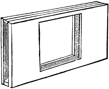
Fig. 2
These slides will be too small to use in the lantern by themselves, so you will have to make a wooden slider for them. This is made as in Fig. 2.
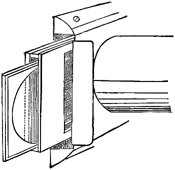
Fig. 3
Take two pieces of board one-eighth of an inch thick, four and a half inches wide, and eight inches long, with a square hole cut in each three and three-quarter inches square. These boards make the back and front of the slider, and are joined together at the top and bottom by two narrow strips of wood eight inches long, a quarter of an inch wide, and one-eighth of an inch thick. This slider is pushed into the slide-stage of the lantern, and the glass slides pushed into it as in Fig. 3.
The slider is rather smaller than the stage in the lantern, which allows of it being adjusted so that the centre of the picture is in a line with the centre of the lenses.
For making movable slides, such as slipping-slides, lever-slides, rack-slides, and chromatropes, you will require wooden frames.
To make these frames, get a carpenter to cut you some slips of pine or deal three or four feet long and half an inch square, with a groove running all along one side of each slip say one-eighth of an inch deep and one-sixteenth of an inch wide. Make your frames out of these slips of wood, seven inches long and four inches wide, outside measuring. Fit a glass in the groove like a slate is fitted in its frame.
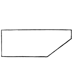
Fig. 4
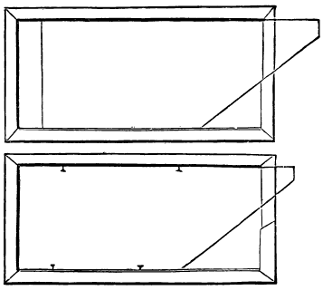
Fig. 5
Make about a dozen of these frames, and set them on one side to dry. Now cut some strips of glass three inches wide and seven inches long, and cut off one corner of each, as in Fig. 4, at any convenient angle, and then cut away the upper half of the front part of each frame flush with the glass, to allow the second glass to be pulled out about half an inch when put in position in the frame, as in Fig. 5.
Fig. 6
Your frames are now ready to receive the design. Trace the design on the inside of the fixed glass with the effects; if it is to be a figure raising and lowering its arm, the figure must be drawn with three arms—viz., the arm that is not raised and the other arm in each position, one up and the other down, as in Fig. 6. The other glass has nothing on it but two black patches, one or the other of which covers one or the other of the arms as the glass is pulled out or pushed in.
In painting these slides, all the glass in the frame around the figures is to be blackened with the opaque black, so that all light is excluded except that which comes through the figures. When this slide is painted, varnish it and paste a narrow strip of paper on the top and bottom of the glass for the movable glass to slide on without scratching the picture.
The black patches on the movable glass are painted and varnished on the inside of the glass. To get these in the right place, place the glass in position over the picture, and when pushed in as far as it will go, mark with your black on the outside of the glass the outline of the arm that is to be covered in that position; then pull out the glass as far as it will go and mark in the same way the outline of the other arm; turn the glass over and fill in the outlines with opaque black, and on putting the glass in its place in the frame you will have a figure with its arms raised or lowered. Now put the glass in its place, and fix it there by pressing into the wood of the frame two small pins at the top and two at the bottom. In putting in these pins allow room for the glass to slide easily.
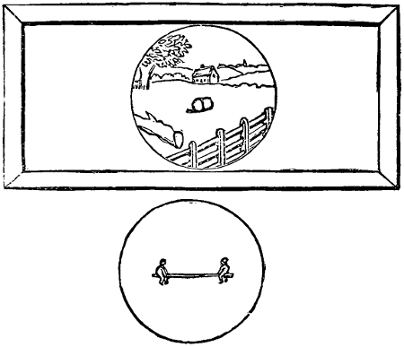
Fig. 7
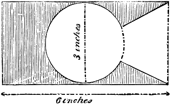
Fig. 8
The construction of lever slides is something like that of the slipping slides, except that the movable glass is circular, and the picture on the glass in the frame is painted circular and has a background. The movable glass has painted on it only the limb that is to be moved. You can get these circular glasses cut at a glazier’s; have them three inches in diameter. Fig. 7 will explain how the two glasses are to be painted. By placing the movable glass over the fixed glass, and moving it partly round and back again, the two boys will appear to move up and down. Of course the point that the board hinges on must be in the centre of the picture. Before painting the picture, cut out a piece of thin board a quarter of an inch thick, three inches wide, and six inches long. Cut this in the shape of Fig. 8 (the dark part represents the wood). Glue this wood on to the glass inside the frame, and cut away the front edge of the frame down to the glass.
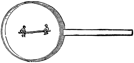
Fig. 9
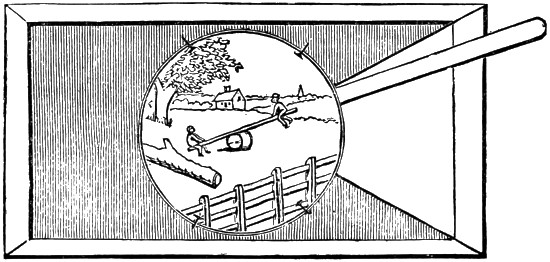
Fig. 10
Now you can paint your picture, and while that is drying take one of your circular glasses and fit a rim—made of thin brass plate, a sixteenth of an inch thick—to it. This rim is to fit the glass tightly, and is to be a quarter of an inch wide; the ends are to lap a little, and are to be soldered together. Now cut from the same brass plate a strip two and a half inches long and a quarter of an inch wide, and solder this on to the rim, as in Fig. 9. Fix the circular glass in this rim, and on the inside paint the board and children on it, put it in its place in the circular hollow in the frame, and fasten it in its place with small pins pressed into the wood and bent over the brass rim (Fig. 10). By raising or lowering the lever the board will rock up or down.
Rack slides are very like the last description of slide, but in these the movable glass is capable of being moved quite round by a rack-and-pinion work.
IV. Revolving Slides for the Magic-Lantern, without Rack-work. By F. Chasemore.
In my last section on magic-lantern slides, I mentioned that, although the frames for rack-work slides could be purchased, they were expensive. I have since then thought that the old-fashioned way of turning the revolving part—viz., by pulley and band—would be easy for boys to make, and answer very well if the cord is kept tight. In this section I give instructions in making these frames.
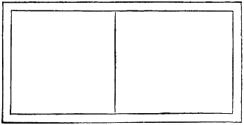
Fig 1
Make the outside frames five inches wide and ten inches long, out of wood half an inch by three-eighths, put edgeways. Cut a piece of thin deal or mahogany three-eighths of an inch thick and five inches square, and glue this on one side of half the frame (as Fig. 1). Cover the other half with a piece of glass four and a half inches square, and fasten it there with strips of deal, making them flush with the board on the other half. Glue corner-pieces (as in Fig. 4) on the other side of the glass, turning the frame over.
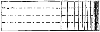
Fig 2
Make the circular frames out of a wooden circular box—such as a tooth-powder box—about four inches in diameter. Take off the lid and cut away the rim that it fits on, and saw the box into rings about a quarter of an inch wide, marking the box first with a pencil, and cutting through the marks with a fine saw (as Fig. 2). Have your circular glasses cut the exact size of the inside of these rings. Fix the glass in each ring so that the wood projects a trifle beyond the glass on one side. With a three-cornered file cut a triangular groove all round each ring about one-sixteenth of an inch deep.
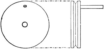
Fig 3
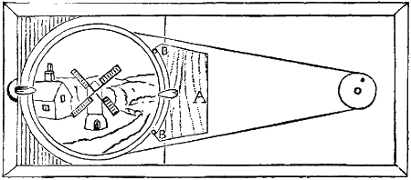
Fig 4
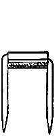
Fig 5
Make the small wheel out of a cotton-reel about an inch or an inch and a quarter in diameter. Cut off the ends and cut the other part into slices a quarter of an inch wide, and cut a groove about an eighth of an inch deep all round each (as Fig. 3). On one side of each of these pieces fix a short wire about three-quarters of an inch long near the edge; this wire will serve as a handle to turn the wheel by. Fasten this small wheel to the board by a screw that fits easily into the hole in the centre, without too much play (Fig. 4). Put the circular glass and frame in its place and glue a piece of wood (A, Fig. 4), about two inches wide and a quarter of an inch thick, to the wooden half of frame. Get two small glass beads about a quarter of an inch long and an eighth of an inch wide. Put a wire about an inch long through each, and bend the wires as in Fig. 5. Sharpen the ends and press them into the edge of the wood (A, Fig. 4, B B), so that the beads will turn easily without touching the wood. Cut away a semicircular portion of the end of the frame (Fig. 4) and fasten a small button made of brass plate in it, and fasten another button to the wood (A). These buttons will keep the circular frame in its place. Connect the two wheels with a piece of strong twine, not too thick, going round them both, and fasten the ends by lapping them and sewing them together. Now if you turn the small wheel the large circular frame will turn round in the same direction if your work is well done. The edge of the circular frame must not touch anything but the glass it rests on, the two beads, and the two buttons. The view is painted on the inside of the fixed glass, and the revolving portion is painted on the under side of the circular glass. In Fig. 4 the mill and background are painted on the fixed glass, and the sails on the movable one.
Chromatropes can be made in the same way, except that the small wheel has two grooves in its edge, and the other part is made up of two revolving frames, which are turned in opposite directions by one cord passing round both and the small wheel. The lower frame rests on the square glass, and the other frame rests on the lower one. The cord is passed from the right-hand side of the lower groove in the small wheel up the right side of the lower frame, round the top and down the left side to the left side of the upper groove in small wheel, round the upper groove to right side up to the left side of upper frame, round the top down the right side of frame to left side of lower groove of small wheel, brought round, and the two ends joined. It will be seen that by putting the cord this way the two frames are turned in opposite directions, although the small wheel turns them both. Have the cord tight, and well rub all the parts that work together with blacklead.
In painting chromatropes, each glass is painted with the same pattern, and then they are placed face to face, and in turning make very elaborate and constantly-changing figures.
V. Screen Frame for the Magic-Lantern. By Frank Chasemore.
Great inconvenience is often caused in fixing a screen in a room for the lantern, such as taking down pictures, etc.; and sometimes it is impossible to hang it without doing some damage to the walls and paint by driving nails and hooks. Even then the screen has to be put up in an inconvenient place.
By using the following contrivance all this will be avoided. The screen can be put in any part of a room most suitable for the show, and afterwards taken to pieces in a few minutes and packed away in a box thirty-six inches long and about eight inches deep and wide.
The frame, or stand, can be bought at the shops, but it is much cheaper to make your own.
The materials for this frame can be bought at a small outlay, and are—fifteen wooden rods three feet six inches long and about an inch and a quarter in diameter—the handles sold at the shops for fitting to hair broom-heads do very well indeed, and are not very dear; two pieces of wood six inches long, five inches wide, and one inch and a quarter thick; and, lastly, some stout tin plate.
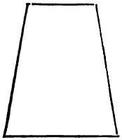
Fig. 1.
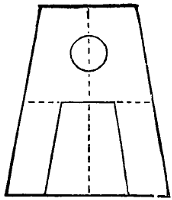
Fig. 2.
First of all, take the two wooden blocks and cut them the shape shown in Fig. 1; the width at top is three inches, and at the bottom five inches. Divide the top and bottom lines into two equal parts, and draw a line from top to bottom through the points of division. On this line mark a point an inch and a half from the top, and with this point as centre bore a hole right through the wood, which hole is to be just large enough for the wooden rods to fit tightly into. Draw a line across the face of the block half way down (as in Fig. 2). Along this line, and from each end of it, mark inwards a distance equal to the diameter of the wooden rods, and do the same along the bottom line (as in Fig. 2). Join these points as in the figure; cut out the middle portion, leaving the projections three inches long and an inch and a quarter square. These projections must be rounded by taking off the corners with a sharp chisel or knife. Trim them down till they are the same size as the rods.
Now you will want your fifteen wooden rods. See that they are all the same thickness. Cut off the ends of each, to make them quite square, and making the rods exactly three feet six inches long. From your tin plate cut fourteen pieces, each piece to be six inches long, and wide enough to go round the rods and to lap about a quarter of an inch. The width can be found by rolling paper round the rod and letting it lap a quarter of an inch, and then cutting it off. Place this paper on the tin and mark the width. The tin can be cut with a large pair of scissors. Now roll each piece of tin round the rods so as to form fourteen tubes. These tubes will now require to be soldered. You can get your tinman to do this for you, or you can do it yourself. If so, the following is the way to do it.
First of all, get some muriatic acid and some clean zinc cuttings. Put the zinc into a bottle and pour over it the acid, and set it on one side for a time till it has quite done effervescing; then add a little more zinc, and if it begins again wait a little longer and add more. Do this till it does not effervesce on putting new zinc into it, when it is ready for use. You must get some solder from the plumber’s, and if you have not a soldering-bit he will perhaps lend you one; but you can buy the bits now in many shops where they are sold on a card with some solder. The cost is from one shilling upwards.
The first thing to do is to ‘tin the bit’ (or cover the face and point with solder). This is done as follows. Place the bit in the fire to get hot, but not red. Take a clean piece of tin-plate and put on it a few drops of the zinc solution, and put a small piece of solder into it. When the bit is hot enough take it out of the fire, and with a coarse file clean the face and edges of it, and place it on the solder in the zinc solution on the piece of tin. In a few seconds the solder will melt and flow all over the point of the bit. This must be done to the bit every time it gets red-hot, as in that case the solder is burnt off.
Now put the bit back into the fire and take one of the tin tubes and first clean the surfaces that lap together by scraping them with a penknife. Rub each surface with the zinc solution and lap them together, and tie the tube round with string, to keep the edges in their places. Take the bit out of the fire when it is hot enough, and place it on the end of the stick of solder, which will be melted and stick to the bit. Place the bit on the top of the lapping edges, and in a few seconds the solder will flow from the bit between the surfaces to be joined, and by drawing the bit from one end to the other it will draw after it the solder and make a strong joint. If the bit did not at first carry enough solder to make the whole joint, more can be added by applying the stick of solder to the bit while it is on the joint. Solder the fourteen tubes, and clean off the joints by scraping and filing the superfluous solder off and polishing up with a piece of glass-paper. Clean the joint inside well with a piece of oiled rag to destroy the zinc solution left inside.
Now fit a tube on one end of each of fourteen of the wooden rods. The tube must be pushed on to the wood so that it is half way, or leaving an empty space of three inches. The tube can be fixed to the wood by two or three tacks driven through the tin. The fifteenth rod has no tube to it.
This is all there is to be made for the frame. In putting it together take the rod without a tube and two others, and join them together like a fishing rod, place each end of this compound rod into the hole in one of the blocks of wood, fit together the other rods into sets of three. There will be four of them. At one end of each set will be an empty tube, these are to be fitted on the pegs on the blocks at the ends of the other rod. The frame will now be composed of two uprights, each made up of two compound rods, and these support the cross rod or screen roller.
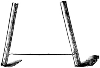
Fig. 3.
In the bottom rod of each set bore a hole with a gimlet, as in Fig. 3, and get two pieces of iron wire about one-quarter of an inch in diameter and bend the ends at right angles to the other part, leaving this middle part about two feet long. These are to be fitted to the rods, one to each pair, by pushing the bent ends into the holes in the ends of the rods as in Fig. 3; they are to be fitted on the outside of the rods.